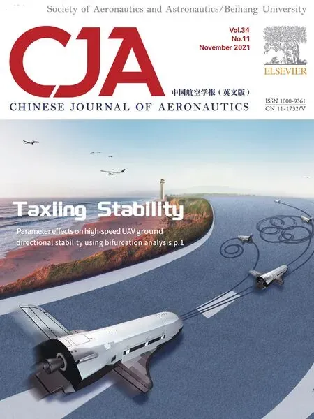
Parameter effects on high-speed UAV ground directional stability using bifurcation analysis
Qiaozhi YIN ,Xiaohui WEI,* ,Hong NIE ,Jian DENG
a State Key Laboratory of Mechanics and Control of Mechanical Structures,Nanjing University of Aeronautics and Astronautics,Nanjing 210016,China
b Key Laboratory of Fundamental Science for National Defense-Advanced Design Technology of Flight Vehicle,Nanjing University of Aeronautics and Astronautics,Nanjing 210016,China
c MIIT Key Laboratory of Multifunctional Lightweight Materials and Structures,Nanjing University of Aeronautics and Astronautics,Nanjing 210016,China
KEYWORDS Bifurcation analysis;Ground directional stability;High-speed UAV;Nonlinear system;Numerical continuation
Abstract A loss of ground directional stability can trigger a high-speed Unmanned Aerial Vehicle(UAV)to veer off the runway.In order to investigate the combined effects of the key structural and operational parameters on the UAV ground directional stability from a global perspective,a fully parameterized mathematical high-speed UAV ground nonlinear dynamic model is developed considering several nonlinear factors.The bifurcation analysis procedure of a UAV ground steering system is introduced,following which the simulation efficiency is greatly improved comparing with the time-domain simulation method.Then the numerical continuation method is employed to investigate the influence of the nose wheel steering angle and the global stability region is obtained.The bifurcation parameter plane is divided into several parts with different stability properties by the saddle nodes and the Hopf bifurcation points.We find that the UAV motion states will never cross the bifurcation curve in the nonlinear system.Also,the dual-parameter bifurcation analyses are presented to give a complete description of the possible steering performance.It is also found that BT bifurcation appears when the UAV initial rectilinear velocity and the tire frictional coefficient vary.In addition,results indicate that the influence of tire frictional coefficient has an opposite trend to the influence of initial rectilinear velocity.Overall,using bifurcation analysis method to identify the parameter regions of a UAV nonlinear ground dynamic system helps to improve the development efficiency and quality during UAV designing phase.
1.Introduction
The aircraft ground taxiing process is one of the most important stages throughout the whole flight.1The statistics2from the Flight Safety Foundation(FSF)show that 30%flight accidents take place during taxiing process and among which,the probability of veering off the runway occupies over 90%.Airbus3has put their effort into the research of a passenger aircraft to try to solve the problem of the stability of aircraft ground maneuvers.This research not only can reduce the taxiing accidents on the runway,but can also improve the efficiency of operations at airports.Owing to the facts including lack of detectability,mechanical failure,unreliable communication link and various landing environments,accidents are more likely to happen on Unmanned Aerial Vehicles(UAVs).4The high-speed take-off and landing features of a high-speed UAV have great impact on the wheeled landing gear designing.5The main-wheel span is short since the UAV fuselage is slim.Moreover,the landing gear strut is longer and the gravity center is higher due to the high angle of attack landing condition.These characteristics all weaken the UAV rollout directional stability and the ground maneuvering performance.6If a UAV ground taxiing system has no ability to return itself to the equilibrium state when a small perturbation occurs,or the UAV cannot taxi along a pre-determined route when a steering instruction is given,the system lack the directional stability.7The investigation of the effects of the key structure and control parameters on the UAV taxiing directional stability will not only reduce runway excursion rate,but will also provide technical support for UAV landing gear designing.8
In the previous studies,the traditional time-domain simulation method and the perturbation method are usually used to develop aircraft ground nonlinear dynamic models and to investigate the parameter influences on the system dynamic performance and stability.Jiao et al.9,10established an aircraft ground taxiing model considering the tire-runway friction force to study the aircraft dynamic response during the braking process.Abzug11built an aircraft rollout perturbation analysis model based on the stability derivatives of tires,and the lateral stability was studied through transient analysis.Plakhtienko and Shifrin12pointed out the nonlinearity between the tire lateral force and the sideslip angle,based on which the aircraft rollout kinetic characteristics and directional stability were analyzed.Gu13established a six-Degree-of-Freedom (DOF) aircraft ground mathematical model and the curvature center of the movement locus was found out when the aircraft is steering.Zhu and Jia14employed a loworder equivalent model in lieu of the high-order nonlinear complex dynamic model to study the aircraft ground steering performance,and showed that a critical velocity boundary exists when steering.Zhang et al.15investigated the dynamic response during the aircraft steering process and the critical stable correlation curve of the nose steering angle and the taxiing velocity was obtained.Taking the tire lateral flexibility into consideration,the envelope surface of the tire later force under various nose steering angles was given and also,the stable steering boundary was obtained.16Song et al.17observed the directional instability of a flying-wing aircraft during highspeed taxi tests and the instability was reproduced in timedomain simulations.Results suggested that the nose wheel lateral velocity and the tire lateral friction force both have great impact on the instability.In addition,several time-domain simulations of the UAV ground steering process were carried out to achieve the limited values of the nose steering angle and the minimum steering radius to ensure the UAV directional and lateral stability.18Moreover,a carrier-based aircraft rollout dynamic model was built to analyze the allowable maximum steering velocity when the aircraft is steering on a carrier.19Although the parameter influences on the aircraft directional stability and the unstable critical points can be obtained by a time-domain simulation method,a large number of repetitive simulations need to be conducted,which is time consuming and will increase the workload greatly during the aircraft designing phase.A UAV ground taxiing dynamic system is affected by several nonlinear factors including the tire force,landing gear shock absorber force,braking force,aerodynamic force and rudder force.Therefore,in order to exploit the advantages in multidisciplinary distributed collaborative design20and in production digital fast design technique,21the nonlinear bifurcation analysis and the numerical continuation method are used in lieu of the traditional methods to identify the parameter regions of the UAV nonlinear ground taxiing system,which helps to improve the development efficiency and quality during aircraft designing process.
Bifurcation theory has been applied in several aviation problems including aircraft flying stability,22,23ground taxiing directional stability,3,24landing gear shimmy25,26and landing gear retraction,27,28which have established a great foundation for aircraft,landing gear and system design.In terms of aircraft ground steering stability,Rankin et al.29analyzed the effects of the nose steering angle and gravity center position on the ground steering system and the corresponding stable region in the dual-parameter space has been found out through the bifurcation analysis method.Coetzee et al.30employed the numerical continuation method to obtain the lateral forces on the landing gears and the fuselage of an A380.Also,the bifurcation simulation results were compared to the experimental data,verifying that the methods applied in the research are reliable techniques to study the aircraft ground steering performance.Comparing to the previous works regarding the bifurcation analysis on aircraft dynamic systems,a fully parameterized mathematical high-speed UAV ground nonlinear dynamic model is developed and the global stability region is found out in this study.The bifurcation parameter plane obtained in this paper is divided into various regions according to different stabilities,which clearly demonstrates the parameter and working condition influences on the system performance.
In addition,the special configuration and the high taxiing velocity of a high-speed UAV trigger some new problems.The lateral velocity component is higher when the UAV is yawing at a fast taxiing speed so that the lateral displacement increases quickly and it is difficult to correct the direction in time.Moreover,the rudder force has great impact on the directional performance.As a result,the effects of the UAV initial rectilinear velocity,the rudder area and the tire frictional coefficient on the UAV ground steering system are all taken into consideration.The dual-parameter bifurcation analyses depending on the additional structural and operational parameters mentioned above are presented to give a complete description of the possible steering performance in the global nonlinear system.
To sum up,the purpose of this study is to analyze the highspeed UAV ground steering stability and to reveal the effects of several key parameters on the UAV ground steering nonlinear dynamic system.In Section 2,a high-speed UAV nonlinear ground taxiing dynamic autonomous system is built in MATLAB/Simulink considering several nonlinear factors.In Section 3,the applied bifurcation theory and numerical continuation method are introduced for possible initiation and developments in bifurcation softwares.Then in Section 4,the bifurcation analysis procedure of UAV ground steering system is also introduced,following which the simulation efficiency is greatly improved comparing with the time-domain simulation method.In Section 5,both single-parameter and dualparameter bifurcation analyses are carried out.The stable regions are divided on the parameter plane to illustrate the UAV possible state motions and some new bifurcation phenomena are found out in the high-speed UAV ground maneuvering system.Finally,Section 6 provides the conclusions.
2.UAV taxiing dynamic model
A UAV can taxi straightly on the ground at a constant speed under the combined action of several nonlinear forces including the landing gear buffering force,the tire force,the aerodynamic force,the rudder force,the drag parachute force and the motor power.When a steering signal is given,the UAV motion state will change and a bifurcation may take place under the influence of these nonlinear factors,which would lead to system instability.Therefore,a UAV taxiing dynamic model is built here to study the system performance and the parameter effects using the bifurcation analysis method.
2.1.Assumption
In order to improve the computational efficiency and at meanwhile to ensure the modeling precision,three assumptions are made when building the UAV ground taxiing dynamic model:
(1) The UAV fuselage and the landing gear components are regarded as rigid and the flexibility is neglected.The landing gear axle buffering force and the buffer stroke are taken into consideration.
(2) The UAV is considered symmetrical in both the structure and the mass distribution,thus the corresponding products of inertia are 0.
(3) The mass variation resulting from the engine fuel consumption is neglected.And in order to ensure the UAV initial uniform linear motion,the engine thrust is considered constant during every taxiing period.
2.2.Landing gear buffering force
A UAV landing gear is used for landing drop load reduction,braking,steering and vibration control during take-off,landing and taxiing process.The shock absorber of the UAV is oleo-pneumatic,and the nonlinearity lies in the relationship between the buffer axle forceFsand the buffer strokes,which is shown in Fig.1.The curve in Fig.1 illustrates the energy the buffer absorbs during the landing impact process.The whole working process of the shock absorber is from pointAto pointBalong the curve.
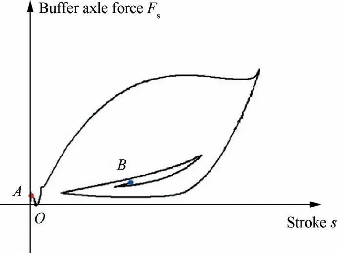
Fig.1 Nonlinear buffer axle force.
The buffer axle forceFsincludes the air spring forceFair,the oil damping forceFoil,the friction forceFf,and the structural restraint forceFstgenerated from the fully extension or the fully compression positions.Therefore,the buffer axle forceFsis given as31:

Neglecting the heat exchange between the air in the air chamber and outside,the air spring force can be expressed as:

whereAaandP0are the effective area and the initial air pressure intensity in the air chamber,respectively.V0is the initial air chamber volume,nis the air polytropic exponent,Patmis the atmospheric pressure.
The shock absorber has some side oil holes,thus the oil damping forceFoilis a function of ˙s,which is the derivative of the buffer stroke versus time.The oil damping force is given by:

where ρoilis the oil density,Ahis the effective area in the oil chamber,CdandAdare the contracted flow coefficient and the hole area of the main oil hole,respectively.Ahsis the effective area in the oil returning line,Cdsis the contracted flow coefficient of the side oil hole,Anis the hole area of the oil returning line.
The relative motion between the shock absorber outer cylinder and the piston can create the friction force,the portion of which is caused by the pressure on the shaft sleeve and the other portion is the coulomb friction caused by the landing gear strut bending motion.
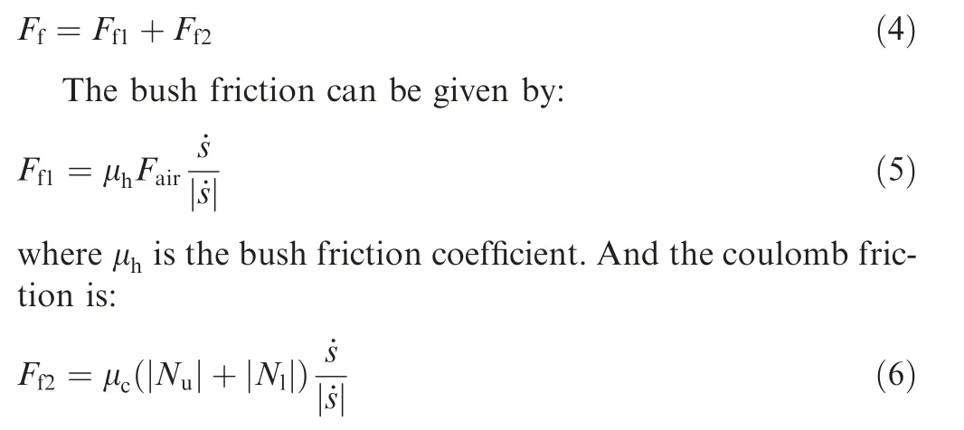
where μcis the coulomb friction coefficient,Nu,Nlare the normal pressures on the top and bottom points of the shock absorber.
When the piston reaches to the maximum stroke,the structural restraint force will be generated:

whereKstis the stiffness of the shock absorber strut,smaxis the maximum buffer stroke.
2.3.Tire force
The tire lateral force is a nonlinear function of the tire sideslip angle and the vertical reaction force.βn,βml,βmrare the sideslip angles of the nose and two main tires.A sideslip angle is defined as an included angle between the taxiing direction and the tire symmetry plane.The UAV ground velocityVcan be decomposed in the stability coordinate system

whereLsbis the transfer matrix from the body coordinate system to the stability coordinate system.The velocity componentvxnin the nose tire symmetry plane can be calculated as:

where θlis the nose steering angle controlled by a steering gear,ris the yaw rate,anis the distance between the nose landing gear and the UAV gravity center.The velocity componentvynvertical to the nose tire symmetry plane is:

The main tires are fixed on the main landing gears without a steering DOF.Therefore,the velocity componentsvxml,vxmrof the two main tires are given by:

wherebwis the main-wheel span.The componentsvyml,vymrvertical to the tire symmetry planes are:

where,amis the distance between the main landing gear and the UAV gravity center.Then the nose tire sideslip angle βncan be expressed as:

Similarly,the main tire sideslip angles βml,βmrcan also be obtained.
When the sideslip angle is small,the tire lateral force is linear to a tire sideslip angle.And as the angle becoming larger,the lateral force increases nonlinearly33to a maximum valuefymax,corresponding to a saturation value of the sideslip angle βsat.If the angle continues growing,the lateral force will reduce gradually till the sideslip angle reaches 90°where the direction of the velocity component in the tire symmetry plane reverses.Extending the sideslip angle range from [0,90°] to [-180°,180°],the loading features between the tire force and sideslip angle are the same in every small range including [-180°,-90°],[-90°,0]and[90°,180°].Therefore,the nose lateral tire force in the range of [-180°,180°] is calculated as29:

Similarly,the lateral forcesfyml,fymron the two main tires can be obtained.
The tire vertical deformation during the taxiing phase is related to UAV attitude angles and buffer stroke.The ground reaction force on the tire is a nonlinear function of UAV pitch and yaw angles.The nose tire vertical deformation δznis calculated as:

wherezbis the vertical distance of the UAV gravity center,snis the nose landing gear buffer stroke,θ is the UAV pitch angle.Then the vertical velocityvznat the nose wheel axle can be given by:

wherewis the UAV velocity component in the vertical direction in the body coordinate system,qis the pitch angular speed.Also,the tire vertical deformation of the two main tires can be calculated as:

wheresml,smrare the buffer strokes of the main landing gears,ψ is the UAV yaw angle.Similar to Eq.(17),the vertical velocities at the two main wheel axlesvzml,vzmrcan be obtained after the derivation of Eqs.(18) and (19).
The tire vertical force can be taken as a first order spring damper system34,thus the nose tire vertical force is given by:

where,kznis the tire vertical stiffness,cznis the vertical damping coefficient.By analogy,the main tire forcesPml,Pmrcan also be calculated.
2.4.Nonlinear dynamic model of UAV ground taxiing system
The diagram depicting the UAV steering process and force analysis is shown in Fig.2.The yellow dashed line is the runway centerline.If the UAV is taxiing on a runway with a bend,a turning instruction will be received,leading the nose wheel turning an angle θl.The wheel tracks are the blue curves in Fig.2.
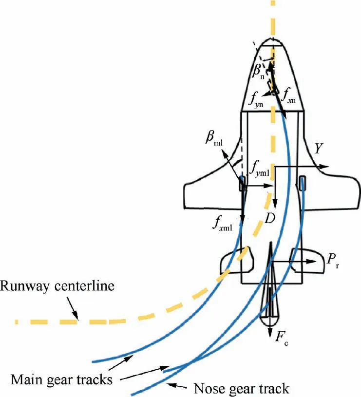
Fig.2 UAV steering process and force analysis diagram.
The nonlinear state equations of the UAV taxiing system in the body coordinate system can be obtained based on the momentum and momentum moment principles:
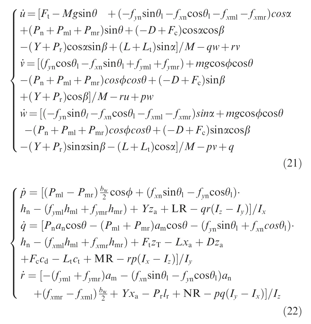
where,u,vare the UAV velocity components inx-andy-directions in the body coordinate system.Ftis the engine power,Mis the UAV mass,fxn,fxml,fxmrare the tire longitudinal friction forces,α is the angle of attack,L,D,Yare the aerodynamic forces,Fcis the drag parachute force,Pris the rudder force,Ltis the elevator force,β is the UAV sideslip angle.φ andpare the roll angle and angular speed,respectively.LR,MR,NR are the aerodynamic moments.Ix,Iy,Izare the inertia moments of the three coordinate axes in the body coordinate system.hn,hml,hmrare the vertical distances from the UAV gravity center to the touchdown points of the three tires,respectively.xa,zaare the projector distances between the aerodynamic center and the UAV gravity center alongx-axis andz-axis.cdis the distance between the drag parachute force and the gravity center.ctis the projector distance between the elevator force and the gravity center alongx-axis.zTis the projector distance between the engine power and the gravity center alongy-axis.lris the projector distance between the rudder force and the gravity center alongy-axis.
In addition,on the basis of the transfer matrix of the body and ground coordinate systems,the state equations describing the UAV linear motion can be obtained:
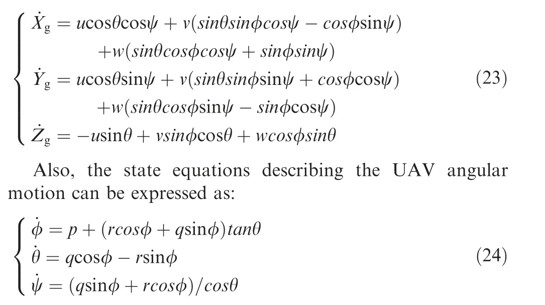
whereXg,Yg,Zgare the UAV movement distances in the ground coordinate system.For all the variables located at the left side of Eqs.(21)–(24),a dot notation is used to show the first derivative with respect to the time of the variables.Eqs.(21)–(24) form the nonlinear dynamic model of the UAV ground taxiing system.
The parameter definitions and the corresponding values are listed in Table 1.

Table 1 Parameters and their values used in UAV model.
3.Applied bifurcation theory and numerical continuation method
Owing to the fact that the UAV ground taxiing dynamic system includes several nonlinear terms,bifurcation analysis and numerical continuation method are powerful tools to study the stability of this system.
The stability and performance of a nonlinear dynamic system depend on the characteristics of the equilibrium points and periodic orbits.A parameter,whose variation can result in the system property change,is called a bifurcation parameter.Eqs.(21)–(24)describe a dynamic autonomous system with bifurcation parameters,which can be written as:

wherex∊Rnis the state variable vector,μ∊Rmis the bifurcation parameter vector.When Eq.(25) is equal to 0,that is:

the solutionx0of Eq.(26) can be obtained,which is called an equilibrium point of the system.The matrix [∂f/∂x]|x=x0is the Jacobian matrix at the equilibrium pointx0.
In order to study the bifurcation characteristics of system solutions,the solution trajectories which is difficult to calculate,need to be obtained as the bifurcation parameter is varying.Thus the continuation method is adopted instead to solve numerical solutions.When using this method,the solution curve of system Eq.(26)is tracked under very small steps from an initial solution so that the influence of the bifurcation parameter on the solutions can be achieved.
Neglecting differences between the state variables and the bifurcation parameters in system (26),an augmented statevariable vectory=(x,μ)∊Rn+mcan be introduced.Thus Eq.(26) can be written as:

Assuming that the vector functionf:Rn+m→Rnis smooth enough,the solution of Eq.(27) with one bifurcation parameter defines a smooth curve inRn+1.
System Eq.(26) with one bifurcation parameter can be transformed into an Ordinary Differential Equation (ODE)so as to track the system numerical solution:
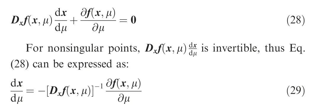
Given an initial conditionx(μ0)=x0,the integral curve of Eq.(29) through the point (x0,μ0) can be calculated using an ODE numerical method.However,owing to that the integral curve is implicit in Eq.(25),a modification of the solution procedure is needed,where the Newton iteration method is employed:

The initial value of the iteration is an approximate solution of Eq.(29),and then the predictor-corrector method is used to obtain the solution curve of Eq.(27)inRn+1.This continuation method is called pseudo-arclength continuation35,36,which can be used together with the trial and error method to figure out the numerical solution of a nonlinear system bifurcation phenomenon effectively.
Three elementary types of one-parameter static bifurcation include saddle node,pitchfork and Hopf bifurcation.Based on the results of one-parameter bifurcation,dual-parameter bifurcation is available using universal unfolding method.
Bogdanov-Takens (BT) bifurcation37is one of the most typical 2-codimension bifurcation types.Codimension38is a value used for measuring space sizes.BT bifurcation takes place in a dual-parameter autonomous system and the system characteristics lie on the two bifurcation parameters μ1,μ2.Assuming that whenμ=0,the equilibrium point of the system isx0=0and the Jacobian matrix [∂f/∂x]|x=x0possesses double zero eigenvalues,then BT bifurcation occurs.The critical equilibrium pointx0=0is the double root of Eq.(26)andμ=0is the starting point of two saddle node bifurcation curves,a Hopf curve and a saddle-homoclinic bifurcation curve.No other kinds of bifurcation appear near a BT bifurcation point except two equilibrium points and a limit cycle at most.
The local topological equivalent system near a BT bifurcation point is given by:

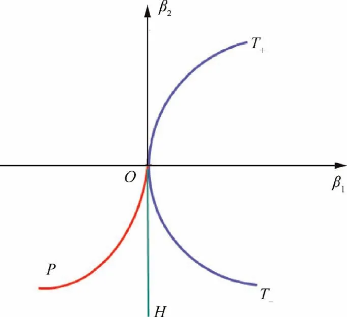
Fig.3 Bogdanov-Takens bifurcation.
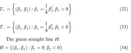
corresponds to Hopf bifurcation.The node and the saddle point meet and vanish together at the point β1,2=0,where a stable limit cycle appears.This limit cycle always exists in a region betweenHand a smooth curveP:

A saddle-homoclinic bifurcation takes place atPand the limit cycle period tends to infinite when it approaches the homoclinic orbit.At meanwhile,the limit cycle degrades and disappears.
4.Analysis procedure of UAV ground steering system
The UAV taxiing and steering process is a constant movement so that an initial moving equilibrium state should be found at first before bifurcation analysis.Then the parameter effects on UAV steering stability can be carried out.Based on bifurcation and numerical continuation method introduced in Section 3,the global stability,stable regions and unstable bifurcation points of the UAV ground steering dynamic system can be obtained quickly.The simulation efficiency of this method is improved greatly comparing with the time-domain simulation method.
The detailed bifurcation analysis procedure on the dynamic performance of the UAV ground steering system will be introduced below.
Step 1.The UAV ground taxiing nonlinear dynamic system model should be built considering all the dynamic factors on the UAV and its six-DOF motions.The state equations in this study are shown in Eqs.(21)-(24).Moreover,a uniform linear motion state should be found through a time-domain simulation,which is then used as an initial working condition during the bifurcation analysis process.Also,the bifurcation parameter value range need to be defined.
Step 2.Fix all the parameters used in the simulation except the main bifurcation parameter μ1(In this study,μ1is the nose wheel steering angle θl).The bifurcation points of the steering system need to be obtained by the numerical continuation method as μ1varies within its value range.Then the oneparameter bifurcation plane can be plotted,which demonstrates the influence of μ1on the UAV ground steering stability.
Step 3.According to the bifurcation points locations and bifurcation types,the parameter plane achieved in Step (2)can be divided into several regions with different properties.Then for the special points on the plane,some time-domain simulations are conducted to study the system dynamic responses.
Step 4.By setting out from the obtained bifurcation points on the one-parameter bifurcation plane,a dual-parameter bifurcation analysis is then carried out using the universal unfolding method after introducing an additional bifurcation parameter μ2(In this study,several additional parameters are studied including the constant rectilinear velocity,the rudder area and the friction coefficient between tire and ground).Then a bifurcation surface and some new bifurcation points can be found out so that the effects of the two parameters on the system stability and the UAV steering motion states can be investigated at the same time.
5.Bifurcation parameter analysis
5.1.Effect of nose wheel steering angle
5.1.1.Bifurcation analysis
In this section,a one-parameter bifurcation analysis will be carried out,as described in Step 2 and Step 3 in Section 4.In order to guarantee the steering stability under various taxiing speeds,different nose wheel steering angles need to be chosen on a bend.In this section,the influence of the steering angle θlon the system bifurcation characteristics is conducted,the corresponding bifurcation curve and stability parameter plane of which is shown in Fig.4.Before the steering command is executed,the UAV is running at a constant speed of 77 m/s.The abscissa represents the bifurcation parameter of the nonlinear system θland the ordinate represents the UAV steering velocity.
The parameter plane can be divided into four parts by the arrows with different colours.And the bifurcation curve is also divided into six segments (L1-L6) by five bifurcation points.The black solid lines L1,L4 and L6 are stable equilibrium solutions while three blue dashed lines are unstable solutions.There exist four saddle nodes LP1-LP4 in the system,among which a stable solution and an unstable solution coexist at points LP1,LP3 and LP4,and two unstable solutions coexist at point LP2.HB is a Hopf bifurcation point,where a stable limit cycle appears.The limit cycle attracts all the trajectories of the system solutions.The UAV motion during a steering process will never cross the solution curves on the parameter plane,which means the coloured arrows on the plane will never intersect the six bifurcation curves in Fig.4.
If the UAV steering angle is smaller than about 0.15 rad or larger than about 0.6 rad,that is the UAV initial steering condition is located in the black or red regions on the plane,the UAV motion state will converge to L1 or L6 along the arrow directions.The UAV motion trail during the turning process is shown in Fig.5(a).After the transition from the initial kinestate (illustrated as the green curve in Fig.5(a)),the UAV will always taxi under a fast constant speed along a circular motion with a large radius(illustrated as the black curve in Fig.5(a)).
However,if the UAV initial motion state lies in the greenarrow region,that israd,or θl∊[0.55,0.85]rad while the steering velocity is small,the UAV will finally converge to L4 along the green arrows.The motion trail is demonstrated in Fig.5(b).The UAV starts to steer from the origin along the green curve and at last,it runs along the black small circle at a constant speed.
In addition,if the UAV initial kinestate is located in the purple region in Fig.4,the UAV will taxi along the green curve in Fig.5(c) and will run along the black trail in the end.The steering system will converge to the unstable solution L3,where a Hopf bifurcation occurs so that the UAV enters a periodical motion.
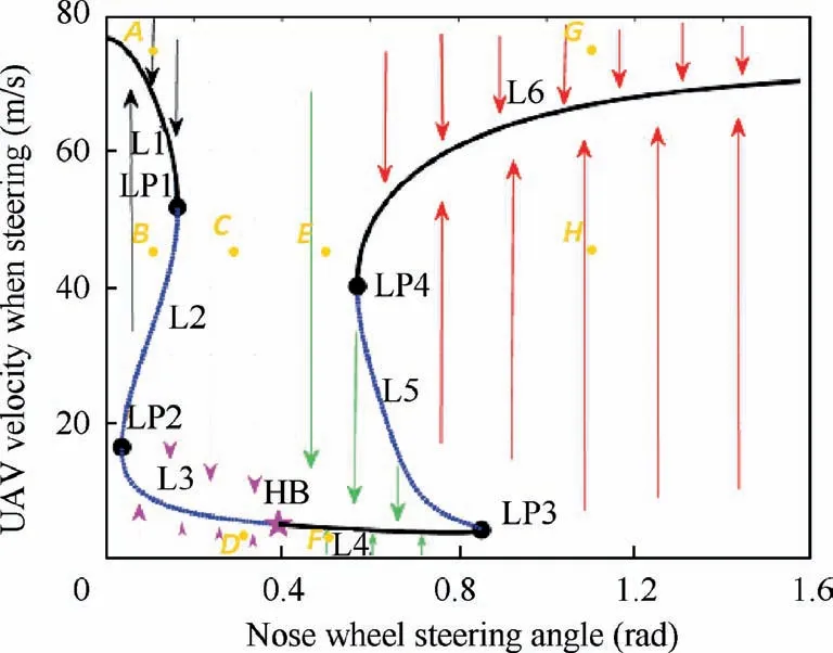
Fig.4 Bifurcation curve and stability parameter plane of the UAV steering motion.
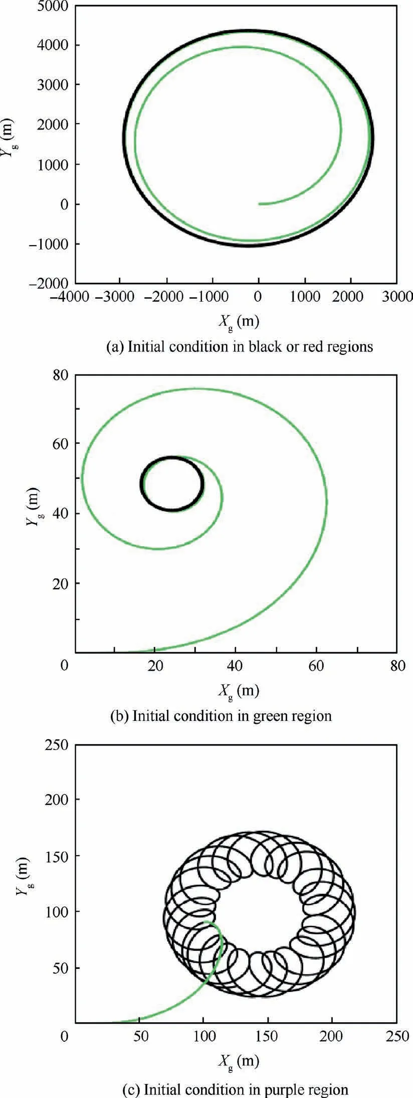
Fig.5 UAV motion trails under different initial conditions.
5.1.2.Validation of the bifurcation analysis
In a previous study,a virtual prototype of the high-speed UAV nonlinear ground taxiing dynamic model39was built in a multibody dynamics software LMS Virtual.Lab Motion and the corresponding virtual prototype modeling method was verified via an aircraft ground taxiing performance test on a scale prototype.40Here,the virtual prototype model is used to verify the validity of the mathematical model built in MATLAB/Simulink and the proposed bifurcation method in this study.Eight steering conditions (see the yellow pointsA-Hin Fig.4) are simulated in the time domain to verify the bifurcation curve in Fig.4.Fig.6 demonstrates the numerical integration results of UAV movement in the time domain using the virtual prototype model in LMS Virtual.Lab Motion.
From Fig.6,it can be seen that if the UAV initial conditions lie in a region of the same colour in Fig.4,they will all converge to the similar stable solutions on one bifurcation curve along the arrows.The initial taxiing velocities of the UAV at pointsA,Bare 75 m/s and 45 m/s in Fig.6(a),respectively.However,both of the eventual taxiing speeds will reach 70 m/s.From the curves of the UAV sideslip angle β in Fig.6(a),we can see that the UAV lateral velocities are constant after 350 s.Therefore,the UAV finally can move along a big circle on the ground at a uniform speed 70 m/s steadily,the motion trail of which is similar to the curve in Fig.5(a).Analogously,Figs.6(c) and (d) illustrate that the UAV will converge to L4 and L6 in Fig.4,respectively.Fig.6(b) shows the performance of the Hopf bifurcation in the time domain.The UAV finally runs periodically within the velocity of[4.52,6.56] m/s and the UAV sideslip angle lies in [-22.37,4.53] °.The movement track is similar to the curve in Fig.5(c).Fig.6 demonstrates the simulation results of the UAV ground steering motion in the time domain using the virtual prototype in a multibody dynamics software agree well with the results obtained by the numerical continuation method based on the bifurcation theory in this study,verifying that the mathematical nonlinear UAV dynamic model and the proposed numerical method are correct and effective.
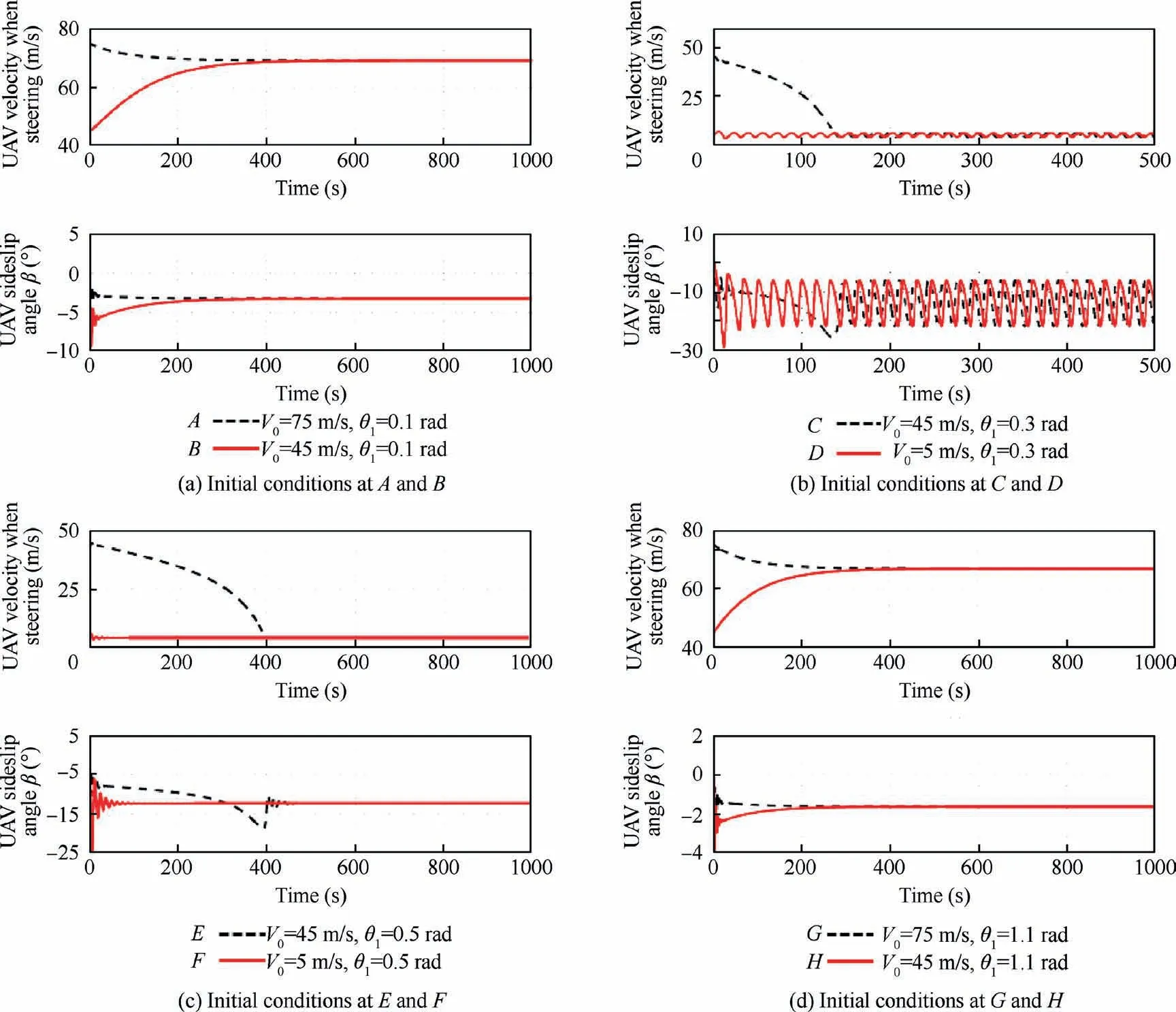
Fig.6 Numerical integration of UAV movement in time domain using virtual prototype model.
5.2.Effect of UAV initial rectilinear velocity
In this section,a dual-parameter bifurcation analysis will be carried out,as described in Step 4 in Section 4.The additional bifurcation parameter is the UAV initial rectilinear velocity,at which the UAV is in an equilibrium movement state and is running in a straight line.
The UAV landing velocity is usually at about 110 m/s and if some special conditions take place,this velocity may approach 125 m/s.For the lower limit in this study,if the UAV initial rectilinear velocity is smaller than 20 m/s,it will not be able to taxi at a constant speed under the combined action of the engine power,aerodynamic drag and tire frictional forces.That is,an initial equilibrium movement state of the UAV steering system can not be found and the UAV will stop in a while owing to the tire frictional forces.Therefore,the value range of the UAV initial rectilinear velocity here is [20,125]m/s.
Starting from the five bifurcation points LP1-LP4 and HB on the parameter plane in Fig.4,the additional bifurcation parameter is introduced to analyze the two parameters influence on the UAV ground steering stability.The dualparameter bifurcation curves are shown in Fig.7.The black solid lines are stable solutions,while the dashed lines represent unstable solutions.Three bifurcation curves L1-L3 exist in the system parameter space,among which L1 and L2 are saddle node bifurcation curves and L3 is a Hopf bifurcation curve.L1 and L3 meet at the point BT,where BT bifurcation occurs.BT bifurcation can determine the equilibrium points and limit cycles of the UAV ground steering system and affect the final motion state under different initial conditions.
From Fig.7,it can be seen that when the UAV initial rectilinear velocity is smaller than 45 m/s,the UAV final motion will always be stable under a nose steering angle in all the parameter range.Although a saddle node curve L2 exists in this region,L2 and all the stable solutions are disjoint.Thus bifurcation will not take place in this region and the UAV can always enter a stable circular motion at a low constant speed.Similarly,when the UAV initial rectilinear velocity is larger than 82 m/s,there always exists a stable solution in the region even if L1 and L3 cross this area.The stable region is in the top left part of Fig.7(b).If the UAV initial state is located in this region,it means the UAV steering velocity is high,which results in a circular motion with a big radius.However,if the UAV initial state is located in the top right part of Fig.7(b),the UAV will accelerate under the constant engine thrust so that the radius of the circular motion increases.According to the centripetal force formula,a bigger radius leads to a smaller centripetal force at a constant steering speed.Thus the tire lateral resultant force is able to provide an enough centripetal force for the stable uniform circular motion.And the UAV will eventually converge to a black solid line during the turning process under a steering angle within[0,π/2] rad.The final stable motion state is similar to that in Fig.5(a).Moreover,Fig.7(b) shows that if the initial rectilinear velocity is faster,the stable equilibrium solution curve is shorter,suggesting that when the initial rectilinear velocity increases,the effect of the nose wheel steering angle on the UAV final steering speed decreases.
Saddle node curves L1 and L2 meet at point CP,which is also called cusp point,from which a saddle node bifurcation takes place.The number of solutions changes when the system crosses this point.When the UAV initial rectilinear velocity is in the range of [45,55] m/s,the bifurcation curve is shown as Fig.8(a).A cusp point disappears and at meanwhile,two saddle nodes appear.The UAV motion state will converge to the black solid line in Fig.8(a) even though the initial motion lies near the blue dashed lines and the UAV motion will not cross the bifurcation curves.If the initial rectilinear velocity is in the range of[55,58]m/s,Hopf bifurcations occur in the system,as illustrated in Fig.8(b).When the UAV initial kinestate is in the neighbourhood of the purple dashed line,the system will be attracted by a stable limit cycle and the UAV may taxi periodically along a track similar to the black trail in Fig.5(c).If the initial rectilinear velocity increases to 60 m/s,L1 and L3 in Fig.7 meet at point BT so that the numbers of the system equilibrium points and limit cycles change.When the velocity is in[60,82] m/s,the point HB1 in Fig.8(b) disappears.And the corresponding bifurcation curve is similar to Fig.4.There exists four saddle nodes and one Hopf bifurcation point.If the initial rectilinear velocity continues rising,points LP1 and LP4 meet and disappear at the same time.Thus L1 and L6 (see Fig.4) join as a stable curve and no bifurcation will occur in the whole parameter space.
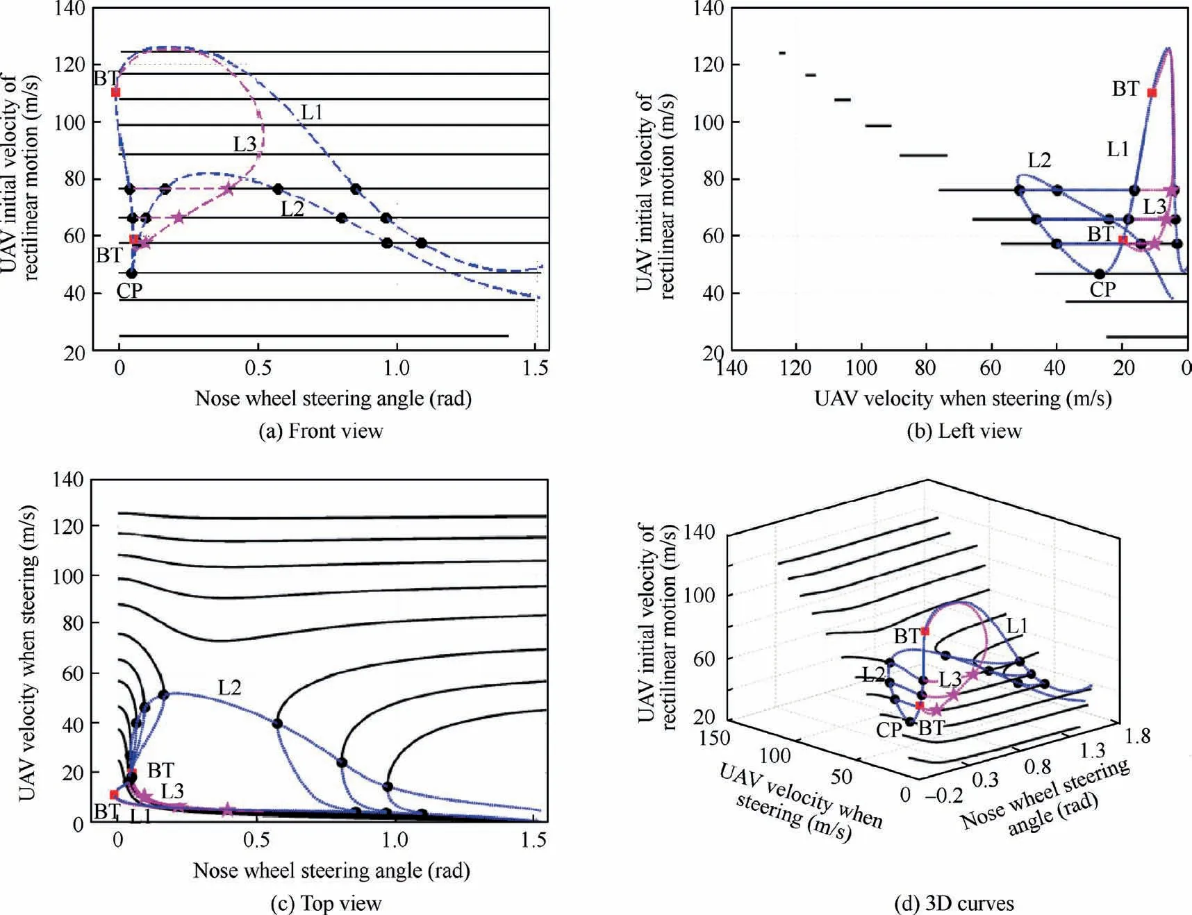
Fig.7 Dual-parameter bifurcation curves under effect of UAV initial rectilinear velocity.
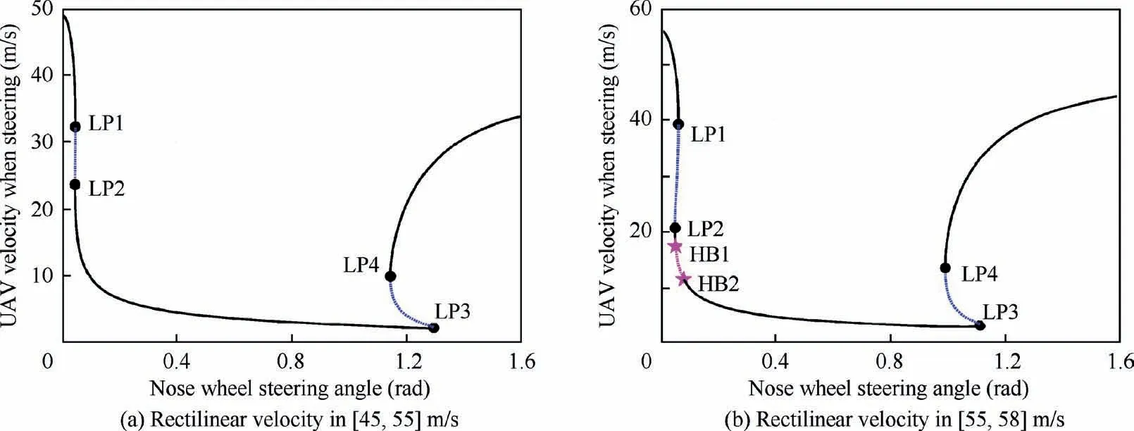
Fig.8 Bifurcation curves under different rectilinear velocities.
5.3.Effect of rudder area
A UAV rudder provides with rudder force during the whole flight,which has a great impact on UAV lateral motion especially when the UAV is taxiing at a high speed.The rudder area is one of the decisive parameters which affects the rudder force greatly.Therefore,the influence of the rudder area on the UAV ground steering stability under a steering command within a steering angle range [0,π/2] rad is studied in this section.Specially,the rudder control system is not included in the UAV ground taxiing dynamic model in this study.The parameter effect analysis is carried out just to give an effective reference and to improve the development efficiency during the UAV rudder designing process.
Similarly,the dual-parameter bifurcation simulation still starts from the one-parameter bifurcation curve in Fig.4.The additional bifurcation parameter is the rudder areaSr,whose value range is[0,3.5]m2in the simulation.The bifurcation result is obtained by the continuation method and the bifurcation surface is drawn in Fig.9.
From Fig.9,it can be seen that when the rudder area isSr∊[0,3.3095]m2,the bifurcation curve obtained from the top view of Fig.9 is similar to the curve in Fig.5.Four saddle nodes LP1-LP4 and a Hopf bifurcation point HB exist on the curve.As the rudder area increasing,the system unstable region reduces,indicating that the stable range of the nose steering angle goes up.From considering the physical changes that the UAV experiences,a larger rudder area will generate a greater lateral force to the UAV,indicating that when the UAV is steering on the ground,the lateral resultant force on the UAV is more likely to provide an enough centripetal force for the circular motion.Therefore,the directional stability is then improved.If the rudder area is larger than 3.3095 m2,the saddle nodes LP1 and LP4 meet and then disappear at the same time.Therefore,the two stable black solid lines form a black solid line so that the UAV can steer along a circle at a constant speed under every steering angle within [0,π/2] rad.
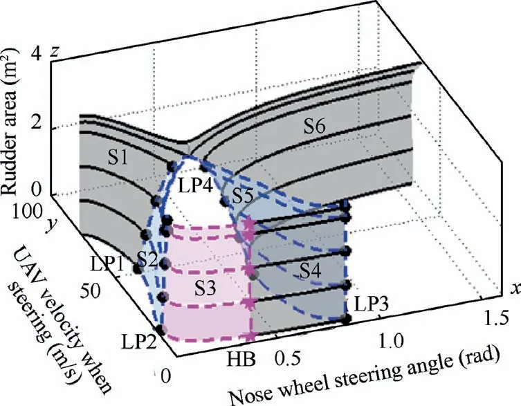
Fig.9 Dual-parameter bifurcation curves under the effect of rudder area.
Six curves with different colours divide the dual-parameter bifurcation space into several regions with various characteristics.If the UAV initial motion state is located in the region surrounded by the grey surface S1,and a surface passing through LP1 and also vertical toxOz,then the UAV can finally converge to the surface S1 and steer steadily at a high constant speed.In addition,if the initial motion state is in the region surrounded by the left blue surface S2,the purple surface S3,and a surface passing through HB and also vertical toxOz,then a Hopf bifurcation will occur in the system.The UAV will converge to a stable limit cycle on S3 and steer periodically at low speeds varying in a small interval.Moreover,the region which is surrounded by the grey surface S4,the right blue surface S5,and a surface passing through HB and also vertical toxOzis stable.The UAV will converge to S4 and at last enter a stable uniform circular motion at a low constant speed.Also,the region on the right side of the surfaces S5 and S6 is stable and the UAV will converge to S6 finally and run in a uniform circular motion at a high speed.
5.4.Effect of tire frictional coefficient
Owing to several factors including weather,tire inflation pressure,tread wear and runway condition,the frictional coefficient between a tire and a runway often changes,which has great impact on aircraft taxiing,braking and steering performance on the ground.In this paper,the UAV runs in a uniform linear motion initially under the action of the engine power,tire friction force and air drag before the steering command.Therefore,the influence of tire frictional coefficient on the steering characteristics is similar to the influence of UAV initial rectilinear velocity,but the trend is opposite.
Fig.10 shows the dual-parameter bifurcation curves under the effect of tire frictional coefficient,the value range of which is μm,n∊[0.002,0.07].Four saddle node bifurcation curves L1-L4 and a Hopf bifurcation curve exist in the parameter space.When the tire frictional coefficient is equal to 0.02,the bifurcation plane is shown as Fig.4.
As the frictional coefficient decreases,the saddle nodes on L1 and L4 move close to each other and meet at the point μm,n=0.008.If the coefficient is smaller than 0.008,the steering motion is always stable when the nose steering angle is located in [0,π/2] rad.The bifurcation parameter plane is demonstrated in Fig.11(a).In addition,with the coefficient decreasing,the black solid line slope varies gently,indicating that the effect of the nose steering angle on the steering velocity reduces.
When the tire frictional coefficient increases to 0.04,the saddle node on L2 and the Hopf bifurcation point on L5 meet.Also,a BT bifurcation takes place (see the red square BT in Fig.10),where the number of the bifurcation points and stable limit cycle changes.Here the saddle node disappears,at the same time a stable limit cycle appears so that the UAV motion state is attracted by the limit cycle.
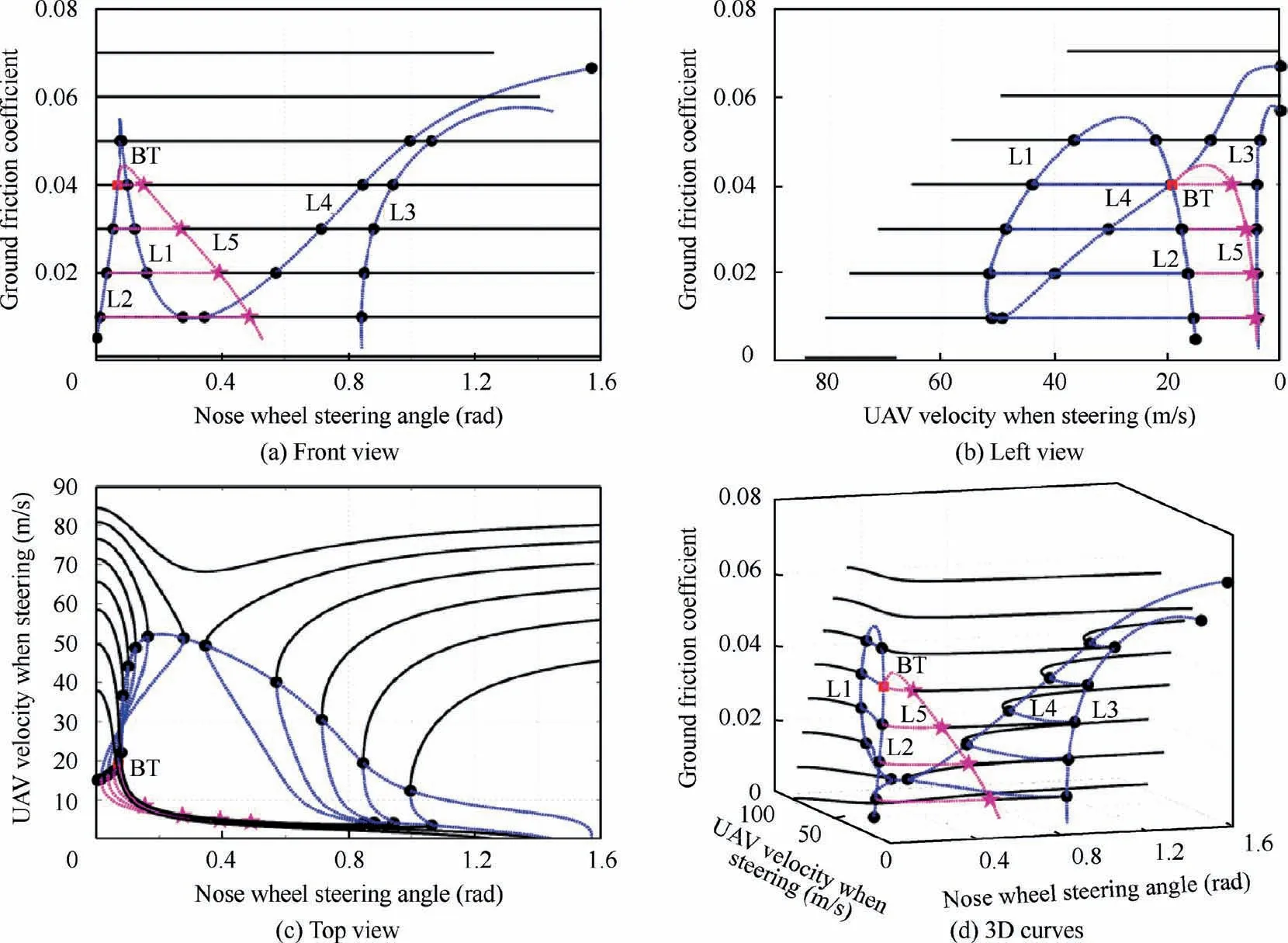
Fig.10 Dual-parameter bifurcation curves under the effect of tire frictional coefficient.
As the frictional coefficient rises,the stable region of the system becomes larger and the Hopf bifurcation area reduces,but two Hopf bifurcation points appear in the system,the bifurcation curve of which is similar to Fig.8(b).If the nose steering angle is about 0.1 rad and the UAV is running along a stable circle,a small perturbation on the steering angle will lead to a Hopf bifurcation in the system,causing an unstable motion that the UAV rotates periodically on the ground.
When the coefficient is within the range [0.045,0.055],the bifurcation curve is similar to Fig.8(a).Only four saddle nodes exist in the system and the Hopf bifurcation points disappear.If the nose steering angle is located near the two saddle node curves,a small perturbation on the steering angle can result in a big change of the UAV steering velocity and the circle radius.
When the coefficient is larger than 0.055,the UAV steering motion is always stable in the whole steering angle range,which is illustrated in Fig.11(b).However,if the nose steering angle is smaller than 0.2 rad,even though the UAV can steer in a stable motion state,a small disturbance has great impact on the UAV steering velocity and the circle radius owing to the abrupt slope of the bifurcation curve.
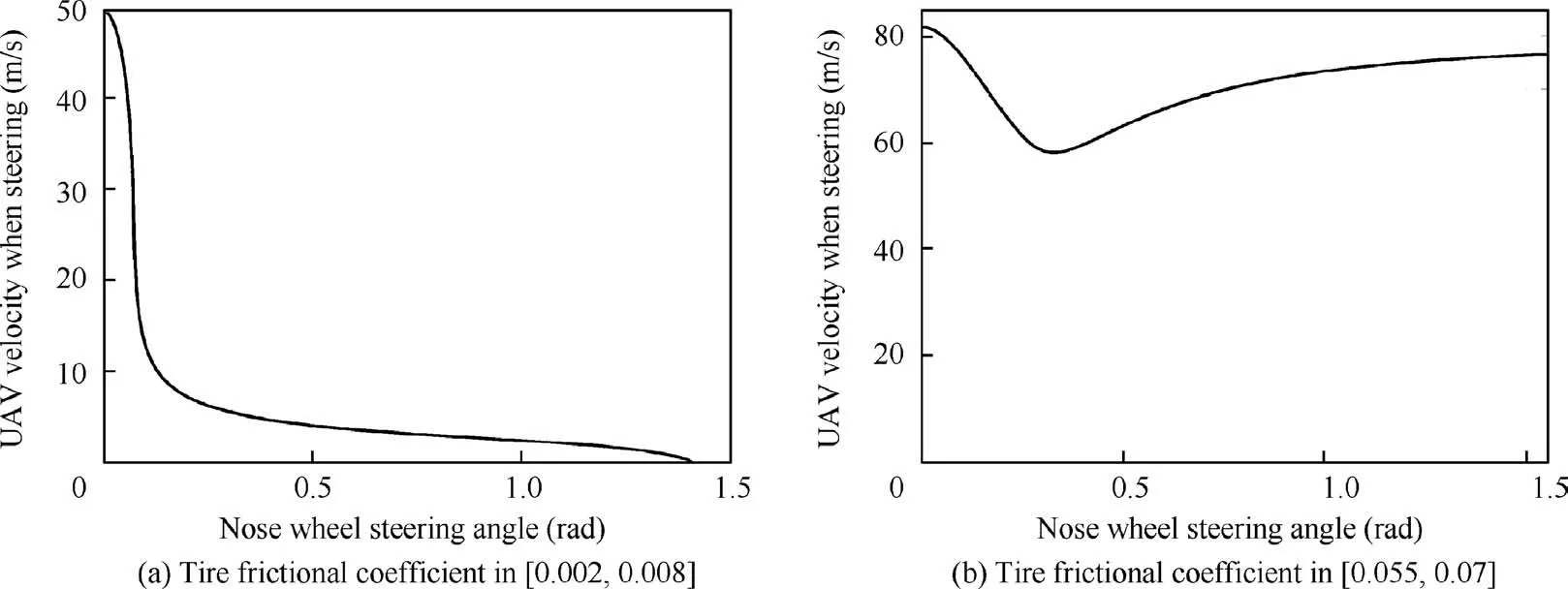
Fig.11 Bifurcation curves under different tire frictional coefficients.
6.Conclusions
The UAV nonlinear taxiing and steering dynamic model is built considering several nonlinear factors including the aerodynamic force,rudder force,landing gear shock absorber force and tire force.The bifurcation theory and the numerical continuation method are employed to carry out the singleparameter and dual-parameter bifurcation analysis.Also,the effects of some key parameters on the UAV ground steering stability is studied.The conclusions are drawn as follows:
(1) Both the UAV nose wheel steering angle and the initial steering velocity during the steering process have great impact on the UAV steering stability.The saddle nodes and the Hopf bifurcation points divide the parameter plane into several parts with different stability properties.The UAV will enter various motion states including the stable uniform circular motions and the periodic motions,which depends on where the initial condition the UAV lies.
(2) If the UAV initial rectilinear velocity is very low or very high,the steering motion is always stable in the whole parameter range of the nose wheel steering angle.As the initial rectilinear velocity increases,the stable equilibrium solution curve becomes shorter,indicating that the influence of the steering angle on the UAV final motion state reduces.BT bifurcation can determine the equilibrium points and limit cycles of the UAV ground steering system and affect the final motion state under different initial conditions.
(3) Increasing the rudder area during UAV designing phase can improve the UAV ground steering stability effectively.As the rudder area increasing,a greater lateral force will be generated to the UAV so that it is more likely to provide an enough centripetal force for the UAV circular motion.Thus the system unstable region reduces,indicating that the stable range of the nose steering angle goes up.This gives an effective reference on the UAV rudder design.
(4) The influence of tire frictional coefficient on the steering characteristics is similar to the influence of UAV initial rectilinear velocity,but the trend is opposite.If the tire longitudinal frictional coefficient is higher,the directional stability of the UAV ground steering system is better.If the nose steering angle is small,even though the UAV can steer in a stable motion state,a small disturbance has great impact on the UAV steering velocity and the circle radius owing to the abrupt slope of the bifurcation curve.
Declaration of Competing Interest
The authors declare that they have no known competing financial interests or personal relationships that could have appeared to influence the work reported in this paper.
Acknowledgements
This study was supported by the National Natural Science Foundation of China (Nos.51905264 and 12002157),the China Postdoctoral Science Foundation Funded Project,China (Nos.2019M650115,2019M661818 and 2020T130298),the Science &Technology Innovation Project for Overseas Scholars in Nanjing,China (No.YQR20046),the National Defense Outstanding Youth Science Foundation,China (No.2018-JCJQ-ZQ-053),the Fundamental Research Funds for the Central Universities,China (No.NF2018001)and the Priority Academic Program Development of Jiangsu Higher Education Institutions,China.
 CHINESE JOURNAL OF AERONAUTICS2021年11期
- CHINESE JOURNAL OF AERONAUTICS的其它文章
- Supersonic flutter control and optimization of metamaterial plate
- Review of in-space assembly technologies
- Utilisation of turboelectric distribution propulsion in commercial aviation:A review on NASA’s TeDP concept
- The influence of inlet swirl intensity and hot-streak on aerodynamics and thermal characteristics of a high pressure turbine vane
- Full blended blade and endwall design of a compressor cascade
- Evolution of wall flow structure and measurement of shear stress issuing from supersonic jet with extended shelf
