Reliable Operation of Turbomachinery Through Bearing Upgrades
Jongsoo Kim
(Waukesha Bearings)
Abstract:Common fluid film bearing issues (mainly high bearing temperature) preventing reliable operation of turbomachinery will be addressed.A theoretical review of radial and thrust bearing performance will be included for a basic understanding on how to handle the bearing issues.Some theoretical plots will be presented to demonstrate the effect of key bearing design parameters on bearing performance.Advanced bearing materials beyond babbitt will also be introduced as bearing upgrade options to overcome bearing issues.Case studies on radial and thrust bearing upgrades to mitigate or eliminate the bearing issues will be shared.Some of the common vibration problems preventing reliable operation of turbomachinery will also be described with suggestions on how to eliminate or mitigate the problems via changes to bearing design features or new bearing technology.A couple of case studies representing each vibration problemwillbepresented.
Keywords:Turbulent;Flexure Pivot Journal (FPJ) Bearing;Integral Squeeze Film Damper (ISFD);Polymer-Lined;PivotOffset;CircularPadThrustBearing.
0 Introduction
Reliable operation of turbomachinery is very important for end users.Minimizing downtime and reducing maintenance costs directly influences their productivity.The operationalreliability of turbomachinery is commonly measured by monitoring bearing temperatures and rotor vibrations.Any changes in bearing temperature and/or vibration indicates that something has changed to the bearings and/or operating conditions.Bearing temperature can be elevated over time for several reasons:changes in bearing loads,changes in bearing clearances,changes in oil supply conditions,etc.Highly elevated bearing temperatures can lead to trips in the machine to prevent a catastrophic failure,which results in production loss and downtime costs.
A comprehensive understanding of bearing temperature behaviors is fundamental to identifying the root causes of bearing temperature changes and being able to propose bearing upgrades to decrease temperature without modifications to the existing bearing housings.This paper presents a simplified energy equation to explain bearing temperature behaviors.The effects of key bearing design factors,such as pivot offset,bearing load vector or bearing orientation,turbulent effect and bearing material,on the bearing temperature are discussed.In tilting pad thrust bearings,the radial pivot location is as important as the circumferential pivot location in bearing performance but has been widely overlooked among the aftermarket bearing manufacturers.This paper addresses that gap and discusses the effects of the radial pivot location on tilting pad thrust bearing performance.Ways to reduce the bearing temperature,including alternative bearing materials that overcome the weakness of babbitt,are explored through several cases.
Furthermore,the fundamental of turbomachinery vibration are explained through simplified rotor models in order to provide insight for bearing upgrade proposals meant to prevent or mitigate vibration issues.A couple of case studies on how to handle vibration issues through bearing upgrades without bearing pedestal modifications (i.e.,as drop-in replacements)are discussed.
1 Fundamentals of Bearing Temperature Behaviors
Bearing temperature is determined from the heat balance around the lubricating film and the bearing or pads.Ageneral energy equation for steady state and a very thin lubricating film can be written as below (Ettles,1980,and Pinkus,et al,1978).

Whereµtis the vortex viscosity induced by turbulent flow.The average across-film temperatureT,along the sliding direction for a very thin lubricating film and a parallel lubricating film shape as shown in Fig.1 can be simplified as equation(3)from energy equations(1)and(2).
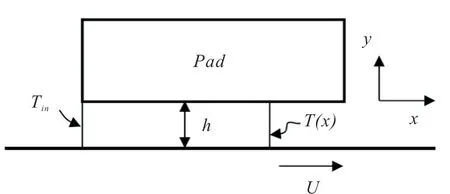
Fig.1 Lubricating film

WhereTinis the inlet film temperature,µis the lubricating oil viscosity,Uis the sliding speed,ρis the lubricant density,cpis the specific heat of the lubricating oil,andhis the film thickness.Andτˉcis a velocity slope coefficient at the sliding surface and can be described as equation (4) with the Hirs turbulent model(Hirs,1972).

by Hirs model(mo=-0.25,no=0.066,Ao=1.2)
WhereReh,a local Reynolds number,is defined asρUh/μ.The inlet film temperatureTinis determined by an oil mixing model as defined by equation(5).

Fig.2 represents the oil flow concept at the pad entrance.In order to reduce the bearing temperature,the inlet film temperature should be kept as close to the oil supply temperature(Ts) as possible.This requires increasing the difference between the required oil flow at the pad entrance(Qin)and the exiting hot oil from the previous pad(Qout).This difference is called‘refilling oil amount’in this paper.The pivot offset in tilting pad bearings increases the refilling oil amount by opening the inlet bearing clearance,as shown in Fig.3.Oil scrapers or an inlet ramp at the leading edge of the pad could also be effective tools for increasing the refilling oil amount.The minimum oil supply should be higher than the refilling oil amount to avoid oil starvation.
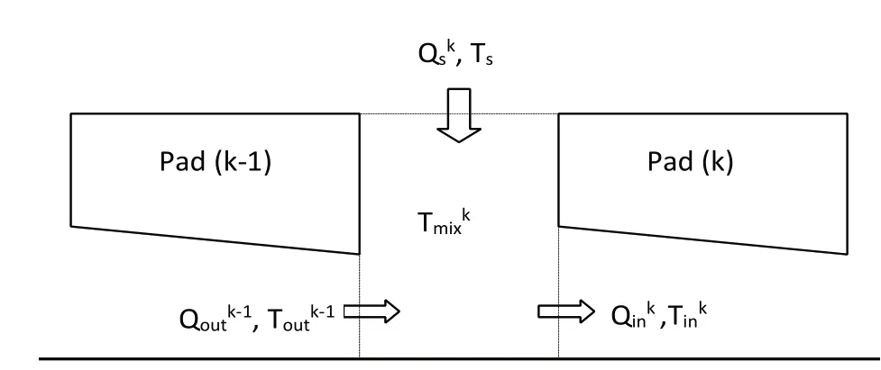
Fig.2 Schematic flow model between pads
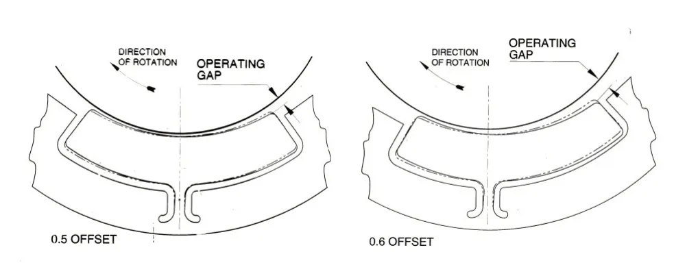
Fig.3 Inlet gap difference by pivot offset

The second term of the right hand in equation (3) indicates the heat generation by shear action at the sliding surface.Minimizing the heat generation can reduce the bearing temperature.At a given speed and bearing load,increasing the bearing film thickness via bearing design techniques is very effective for reducing bearing temperature since the heat generation can be reduced.A shorter bearing length in the sliding direction would be helpful for the reduction of bearing temperature but too short of a bearing length could result in reduced film thickness,which increases bearing temperature.Thus there is an optimum bearing sliding length for minimizing bearing temperature.
The heat generated at the lubricating film is transferred to the surrounding bearing or pad via the thermal conduction of the pad.The amount of heat removal through the pad is determined by equation(6).
WhereTbis the pad surface temperature,tpis the pad thickness,kbis the thermal conductivity of the pad andh∞is the heat transfer rate at the pad surrounding.Higher thermal conductivity of the pad and a higher heat transfer rate can enhance heat removal from the bearing to environment.Chromium copper(CrCu),which has eight times the thermal conductivity of carbon steels,is commonly used as a babbitt substrate for extra-cool bearings.
Fig.4 summarizes a heat balance schematic showing how to manage the bearing temperature around a pad.The most effective way to reduce bearing temperature is to maintain the inlet oil temperature as close to the oil supply temperature as possible.

Fig.4 Heat balance around bearing
Fig.5 shows the predicted film thickness and pad temperature profiles for center pivot (50% offset) and offset pivot (60% offset) tilting pad journal bearings.The pad inlet film thickness of the offset pivot bearing is much increased compared to that of the center pivot bearing.This indicates that the refilling oil amount would be much increased with the offset pivot bearing,which in turn produces a much cooler bearing,by about 14°C as shown in Fig.5.

Fig.5 Pivot offset effects on film thickness profile(left)and bearing temperature(right)
The bearing orientation against the bearing load would make changes in the refiling oil amount and consequently impact on the bearing temperature.Fig.6 shows the bearing temperature versus the load direction vector.The best load angle for bearing temperature is a slightly ahead load between pads (LBP) configuration for center pivot tilting pad bearings.Load angle behind LBP can increase bearing temperature significantly.The best load angle in terms bearing temperature should be analyzed for each specific application.
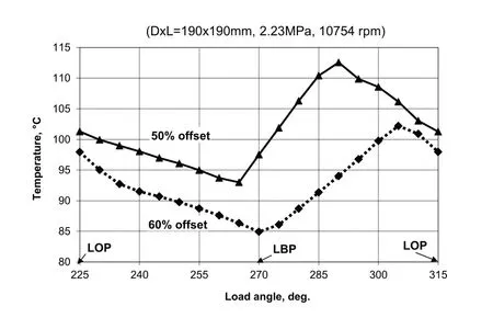
Fig.6 Load angle effects on bearing temperature
The turbulent flow can increase heat generation,as shown in equations (3) and (4).Fig.7 shows the effects of turbulent flow on the film thickness and temperature profiles.Overall bearing temperatures are increased by turbulent flow even though there are no changes to the film thickness.

Fig.7 Turbulent effects on film thickness profile(left)and bearing temperature(right)
The effects of the thermal conductivity of the bearing material and the heat transfer rate at the pad surrounding on the bearing temperature are shown in Fig.8 Materials with higher thermal conductivity are helpful for reducing bearing temperature,and a higher transfer rate makes such thermal conductivity more effective.Therefore,a comprehensive approach that includes managing a higher heat transfer rate is important when applying bearing upgrades for higher thermal conductive material like CrCu.
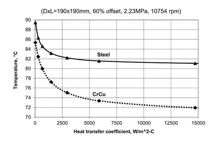
Fig.8 Effects of thermal conductivity and heat transfer rate on bearing temperature
2 Fundamentals of tilting pad thrust bearings
For tilting pad thrust bearings,unlike tilting pad journal bearings,film thickness distribution relies on both the circumferential and radial pivot location as shown in Fig.9 and equation(7).
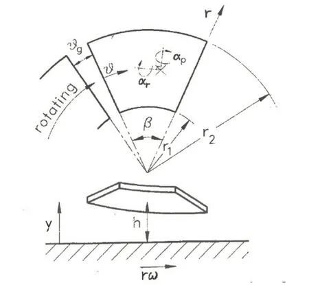
Fig.9 Coordinate of tilting pad thrust bearing

Wherehpis the film thickness at the pivot location,αpandαrrepresent the pitching and rolling tilt angle of the pad about the pivot,andrpandθpare the radial and circumferential pivot location respectively.
The importance of circumferential pivot offset is well accepted,but the effects of the radial pivot location are widely overlooked among the aftermarket bearing manufacturers.The typical rule of thumb for determining radial pivot location is the area mean radius as described in equation(8).

Fig.10 shows the radial pivot location based on the rule of thumb as a function of the pad radius ratio.If the pad outer diameter is double the pad inner diameter,the radial pivot location becomes 58.1%,which is far from the optimum radial pivot location based on the lubrication theory.
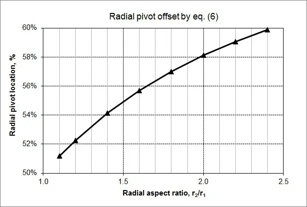
Fig.10 Radial pivot location by rule of thumb
Fig.11 shows an example of maximum pad temperature and minimum film thickness as a function of radial pivot location for two different pad configurations with same pad radius ratio of 2 (152.4 mm OD and 76.2 mm ID).The optimum radial pivot locations using lubrication theory are 46%for the 6-pad configuration and 49%for the 8-pad configuration based on bearing temperature and 48.5% for 6-pad configuration and 50.5% for 8-pad configuration based on minimum film thickness.These values are significantly different from the proposed radial pivot location of 58.1% determined by the rule of thumb.

Fig.11 Effects of radial pivot location on pad temperature(left)and minimum film thickness and film thickness ratio at exit of pad(right)
The pad temperature with the typical radial pivot by the rule of thumb could be hotter by 40°C than the pad temperature with the optimum radial pivot location from lubrication theory,as shown in Fig.11 as an example.For minimum bearing temperatures,the film thickness ratio at pad exit becomes about 0.7,which means the film thickness at the outer radius is thicker by 30%than that at the inner radius.This result is supported by equation (3) since the sliding speed at the outer radius is higher than at the inner radius.The optimum radial pivot location based on film thickness,however,is when the film thickness ratio is around 1.0,which can maximize the flow resistance.Therefore,the optimum radial pivot location should be determined from lubrication theory,not by the rule of thumb.Fig.12 shows an example of thrust bearing failure due to incorrect radial pivot location.

Fig.12 Example of incorrectly designed radial pivot location
3 Case Studies of Bearing Upgrades For Bearing Temperature Problems
3.1 Oil Varnish and Melted Bearing Surface on a Tilting Pad Journal Bearing
A 75 mm tilting pad journal bearing running at 15,249 rpm experienced high bearing temperature and oil varnish issues as shown in Fig.13.The most likely root cause of this failure is a tight bearing clearance and/or electromagnetic or electrostatic shaft current.The measured OEM bearing clearance was close to 0.076 mm which is equivalent to the clearance ratio of 0.001 mm/mm,is a very tight clearance for this bearing size and speed.To decrease the bearing temperature,the existing bearing could be upgraded to a couple of bearing designs.The bearing upgrade should be carefully conducted,however,because this compressor runs with high speed and high discharge pressure (10.3 MPa) which can generate high destabilizing forces from seals.It is reported that the existing bearing runs fine without any vibration issues.
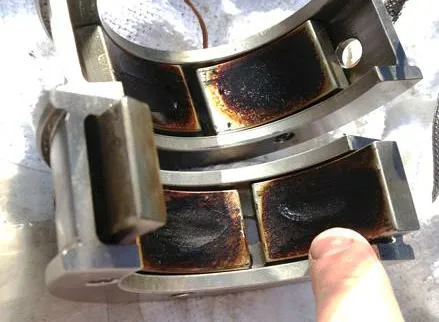
Fig.13 Failed tilting pad journal bearing
Through a couple of bearing and rotordynamic analysis loops (not shown here),an optimum bearing configuration was proposed:a 55% pivot offset with 0.127 mm bearing clearance and preload of 0.286.This bearing upgrade can decrease the bearing temperature significantly as shown in Fig.14,without negatively affecting machine stability.The predicted bearing temperature of the bearing upgrade is 77°C compared to 100°C for the OEM bearing.This bearing upgrade was able to eliminate the high bearing temperature issue and mitigate the oil varnish problem.
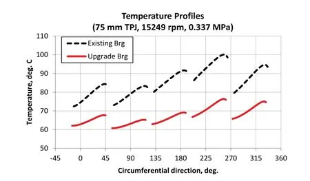
Fig.14 Bearing temperature improvement with upgrade
3.2 Drop-in Replacement of Self-equalizing Tilting Pad Thrust Bearing Through Optimization
A 305 mm,6-pad,center pivot self-equalizing tilting pad OEM bearing suffered a bearing failure due to steam path fouling.The measured babbitt temperature was 110 °Cor higher at the operating speed of 4,405 rpm with the thrust load of 105,600 N,the rated speed is 4,734 rpm.
The OEM bearing pad aspect ratio (ratio of the pad angular length at the mean radiusto the pad radial length) is around 1.33,which means it has a longer pad length in the circumferential direction than the radial direction.The longer bearing length in the circumferential direction could lead to a higher pad temperature according to equation (3).The optimum aspect ratio is close to 1 in most thrust bearings,so the use of 8 pads instead 6 pads would provide a more optimum aspect ratio for this bearing envelope size.The pad temperature and minimum film thickness is significantly improved with this optimum 8-pad configuration,60% angular and 50% radial pivot offset location and use of CrCu pads,as shown in Fig.15.With the bearing upgrade,the predicted pad temperature can be reduced by about 35°C compared to the existing bearing,and film thickness is increased to 0.037 mm from 0.022 mm,which is a 68%improvement.The bearing upgrade adds a significantly higher capacity and safety margin over the existing bearing.

Fig.15 Performance comparison between OEM bearing and upgrade
3.3 Short Bearing Life Due to Incorrect Radial Pivot Location on Tilting Pad Thrust Bearing
An incorrectly designed radial pivot,self-leveling tilting pad thrust bearing as shown in Fig.16 has experienced short life and high babbitt temperature in a blower application.The pads in the current bearing are babbitt with CrCu backing.The operating speed is 3,990 rpm and the lubricant is ISO VG 32 at 49°C inlet temperature.The existing thrust bearing has a 12-pad configuration with center pivot,which is 50%in the sliding direction and more than 60%in the radial direction as shown in Fig.16.
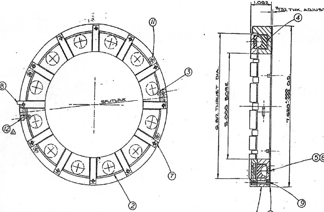
Fig.16 Tilting pad thrust bearing with incorrect design for radial pivot location
The predicted pad temperature and film thickness of the existing bearing are 124°C and 0.007 mm which supports the experience of short life and high babbitt temperature shown in Fig.17.With a 60% circumferential pivot offset and 50%radial pivot offset on the bearing upgrade,the bearing temperature is reduced to 80°C,a drop of 44°C,and the film thickness increases to 0.018 mm,which is a 257% improvement.
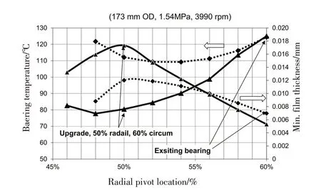
Fig.17 Effect of incorrect radial pivot offset
3.4 Different Materials Than Babbitt for High Bearing Temperature and Long Bearing Life
Fig.18 shows an example of babbitted taper-land thrust bearing upgraded to Beryllium copper(BeCu) Flexure Pivot®thrust bearing to support high speed (156 m/sec at the mean diameter),high thrust load(4.34 MPa)and high oil inlet temperature (60°C).With this upgrade,repeat bearing failure was eliminated.Fig.19 shows a 203.2 mm polymer-lined Flexure Pivot thrust bearing after 10 years of service in a steam turbine.This bearing was an upgrade for a 6-pad babbitted tilting pad thrust bearing due to high bearing temperature and high thrust load.The polymer-lined bearing upgrade eliminated thrust bearing failure to reach more than 10 years of service.
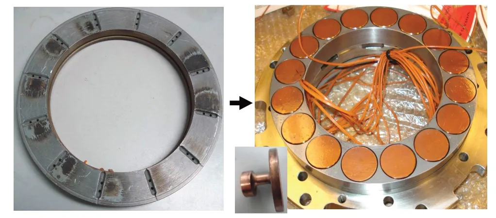
Fig.18 Upgrade from babbitted taper-land thrust bearing(left)to BeCu Flexure Pivot circular pad bearing(right)for high temperature and high load
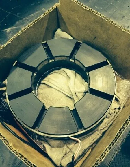
Fig.19 Polymer-lined thrust bearing surface after 10 years of service
4 Fundamentals of Rotordynamics in Turbomachinery
The rotordynamic behaviors of turbomachinery is determined by the rotor,bearing and support (pedestal) dynamic properties (namely,stiffness and damping) and can be explained with a simplified model,as shown in Fig.20.The rotor-bearing system stiffness,which is an‘effective stiffness’,consists ofrotor stiffness,bearing stiffness and pedestal stiffness in series.

Fig.20 Typical rotor vs.equivalent simplified model
The effective stiffness and damping controls the critical speeds of turbomachinery and its amplification factors.The effective stiffness is most influenced by the softest component,as described in equation(9).

The contribution to the effective stiffness from the direct stiffness of the seals are negligible except pumps.As shown in Fig.21,an example of stiffness of each component for a large generator,the effective stiffness of a system for a long,slender (flexible) rotor is most influenced by the rotor stiffness,not the bearing stiffness.In such cases,vibration behaviors cannot be controlled as desired by bearing design changes.Rotors can be unstable when the destabilizing forces from the aero cross-coupling stiffness of seals and/or bearings are higher than the damping forces from the seals and bearings.For this reason,most high speed machines require tilting pad journal bearings to minimize the stability issues.
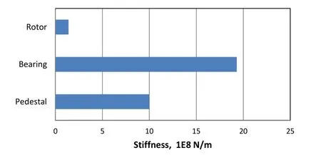
Fig.21 Example of a stiffness comparison for a large generator rotor-bearing system
For flexible rotors,however,tilting pad journal bearings cannot ensure stability.Destabilizing forces from the seals,which are normally located at the higher vibration locations in flexible rotors,as shown in Fig.20,could be higher than effective damping forces.Therefore,in order to provide more damping forces and less destabilizing forces,the flexible rotor should become as close to rigid rotors as possible.The most effective way to achieve this is soften the bearing support.Integral squeeze film damper (ISFD) technology is one tool for softening the bearing support effectively (Ertas,et al,2015,and Locke,et al,2003).By introducing ISFD technology to the rotor-bearing system,the effective bearing stiffness can be comparable to or less than the rotor stiffness,and vibrations at seal locations can be reduced like a rigid rotor.The largest benefit of ISFD technology is that stiffness and damping can be designed independently to meet desired values,which is not possible in conventional fluid film bearings(Ertas,et al,2015).
Vibrations can change over time if rotor imbalances and/or bearing or seal coefficients are altered.Imbalance changes over time are common for units dealing with an adhesive medium;there is frequently buildup of gummy medium on impellers.Seal coefficients can change when seal clearances are increased by rubbing or when an operating condition has changed.Bearing coefficients can change over time through bearing clearance due to pivot wear of tilt pads,such as the wear shown in Fig.22.

Fig.22 Example of pivot wear(left:housing,right:pad)
Pivot wear can significantly impact the bearing clearance for smaller bearing sizes,as shown in Fig.23,which in turn can impact vibration behaviors.Preventing pivot wear of tilting pad journal bearings is very important for reliable operation of machines and can be achieved with Flexure Pivot bearing technology (Kardine,et al,2005,and Zeidan,et al,2003),which is shown in Fig.24.
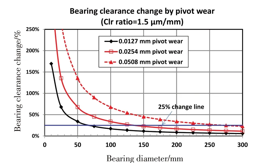
Fig.23 Bearing clearance change by pivot wear
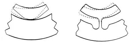
Fig.24 Basic concept of tilting motion on conventional tilt pad(left)and Flexure Pivot tilt pad(right)bearing
5 Case Studies of Bearing Upgrades for Vibration Problems
5.1 Change Critical Speed by Modification to Sleeve Bearing(ID fan)
An induced draft (ID) fan as shown a rotor model in Fig.25 was originally commissioned at 900 rpm without any distinct vibration issues.The operating speed was increased through a rewinding of the motor to a speed of 1,180 rpm.With the OEM bearings,vibration was very high about 20.3 mm/sec which is dangerous,as approaching the new rated speed.

Fig.25 Rotor model of ID fan
A rotordynamic analysis was conducted to identify the critical speed problem.The unbalance responses at the motor end and coupling end bearing locations are shown in Fig.26 with different bearing design options including the OEM bearing (blue line).These unbalance responses are comparable to the measured vibration data provided by the end user,indicating that the rotor model built from scaling the drawing is reasonably accurate.The critical speed determined through the unbalance response analysis is predicted to be at 1,280 rpm with an amplification factor of 8.42 with the current bearing clearance.The current bearing clearance should be modified to move the critical speed further away from the operating speed.The undamped critical speed map (not shown here)indicates that the critical speed cannot be pushed above 1,350 rpm by changes to the bearings alone.To shift the critical speed around 800 rpm below away the operating speed of 1,180 rpm,the bearing support stiffness should be around 5.25E+07 N/m which is not achievable without modifications to the existing bearing pedestal.
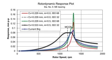
Fig.26 Unbalance response comparisons for different bearing design options
Therefore,the best approach under the current bearing configuration would be the use of a 0.229 mm bearing clearance without preload and a higher viscosity oil.With this solution,the end user was able to reduce the vibration level to 1.0 mm/sec which is very smooth operation.According to the end user,“This is a major reduction from any readings we ever experienced on this fan.I want to thank you guys for yourassistance resolving our long history of vibration issues on this unit.”
5.2 Drop-in Replacement of Sleeve Bearing with Tilting Pad Bearing Due to Sub-synchronous Vibration(Steam Turbine)
A steam turbine supported by a pressure dam sleeve bearing experienced sub-synchronous vibrations (oil whip)at around 10,000 rpm dependent on the load and oil inlet temperature.The continuous operating speed range for this turbine is 9,000 rpm to 11,000 rpm.From a rotordynamic analysisas shown in Fig.27,it was confirmed that the existing pressure dam sleeve bearing could make the steam turbine unstable.
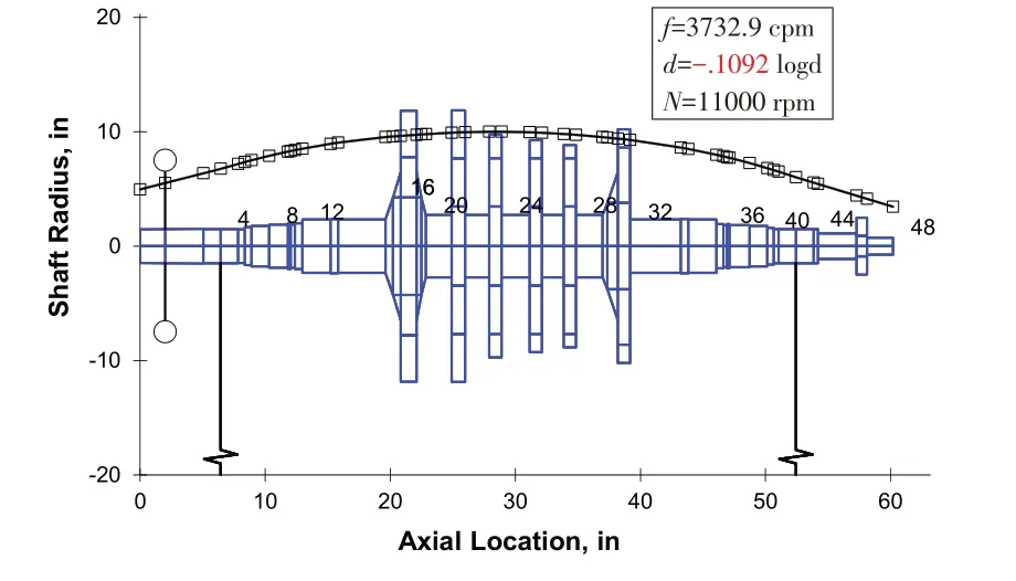
Fig.27 1st forward mode with pressure dam sleeve bearing
In order to eliminate the oil whirl problem,the existing sleeve bearings would have to be replaced with a tilting pad bearing.The proposed Flexure Pivot tilting padbearing for drop-in replacement is described in Fig.28.The Flexure Pivot tilting pad bearing technology is able to fit into the existing sleeve bearing envelope without any modifications to the bearing housing.
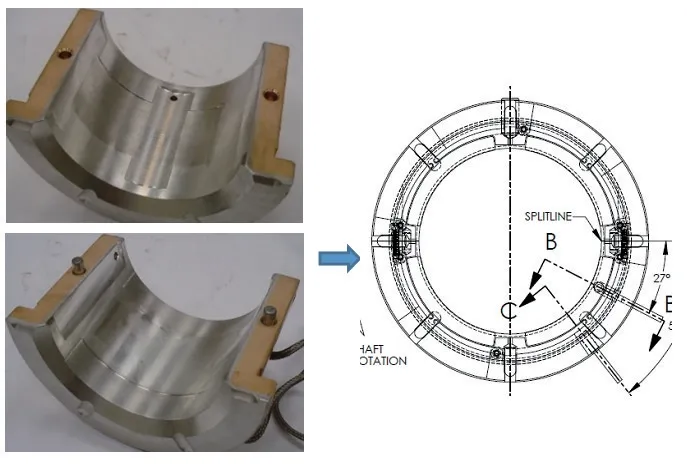
Fig.28 Existing pressure dam sleeve bearing(left)and drop-in Flexure Pivot bearing upgrade(right)
With this bearing upgrade,the log dec of the first mode is increased to 1.6372,which is absolutely stable,from-0.1092 with the existing sleeve bearings,as shown in Fig.29.Therefore,the proposed Flexure Pivot tilting pad bearing can eliminate the oil whip problem.The log dec values of the first mode are plotted in Fig.30 as a function of speed.The existing sleeve bearing could be unstable from 6,000 rpm but the bearing upgrade is absolutely stable for the whole speed range.With the Flexure Pivot tilting pad bearing,the unit is running fine to date.
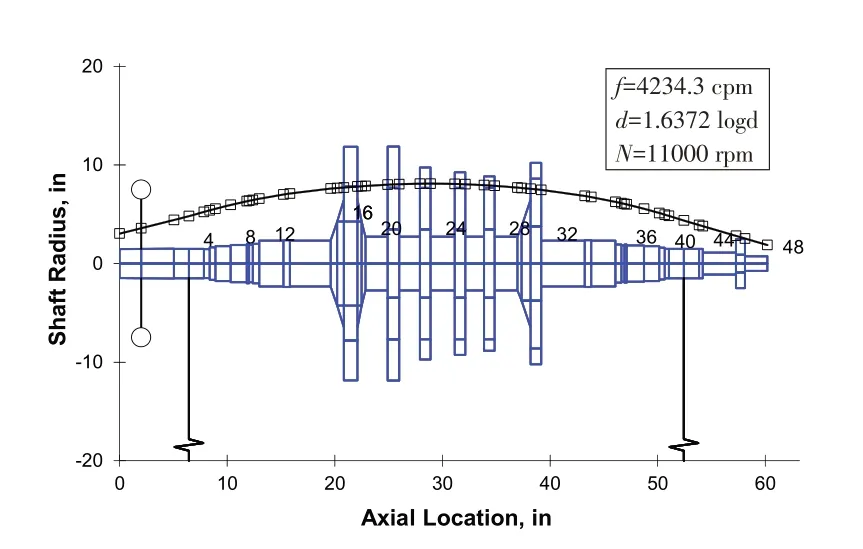
Fig.29 1st forward mode with upgrade bearing
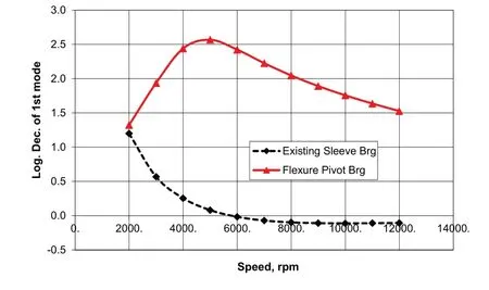
Fig.30 Stability improvement by upgrade bearing
5.3 Drop-in Replacement of Tilting Pad Bearing with Flexure Pivot Bearing with ISFD Technology ToImprove Stability(Turboexpander)
An overhung 1193 kW expander-generator showed significant sub-synchronous vibration at 0.35 times (around 13,500 cpm) the running speed of 38,040 rpm during field testing,as shown in Fig.31.The stability of the first mode showed a negative log dec at a load of 420 kW with aerocross coupling stiffness from the impeller as observed in field testing.

Fig.31 1193 kW turboexpander(left)with sub-synchronous vibration at 35%output(right)
The root cause of the sub-synchoronous vibration was no‘effective’damping from the bearings due to a lack of rotor motion at the bearing locations,as shown in Fig.32.
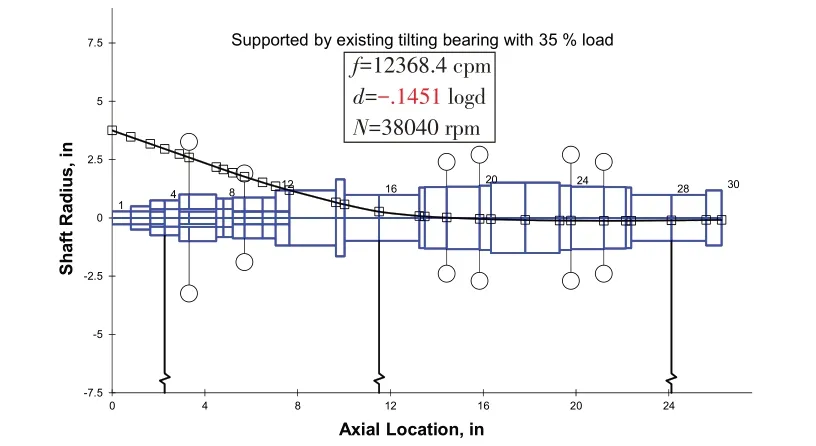
Fig.32 Unstable system with existing tilting pad bearings
The solution,therefore,should be to increase the rotor motion at the bearing locations by decreasing the effective stiffness of bearing system.The bearing stiffness cannot be dramatically reduced,however,due to gear load and high speed.Hence,the bearing support at the impeller end bearing location must be softened.The impeller end bearing was upgraded to a Flexure Pivot journal bearing with ISFD technology,as shown in 34.With drop-in replacement upgrade,the unit has been able to run at full load without any vibration issues since 2003.
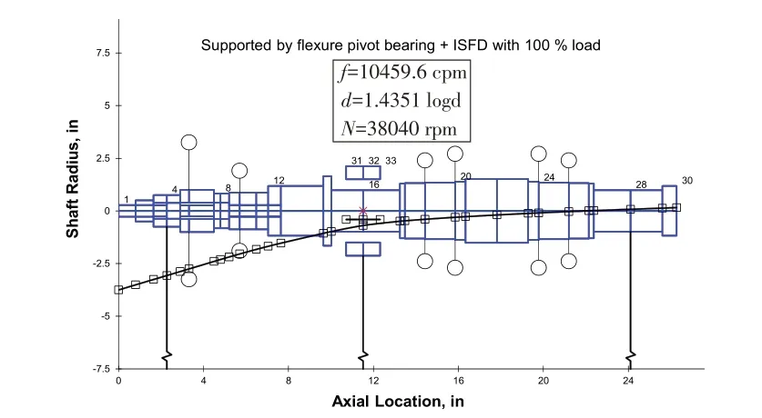
Fig.33 Stable system with Flexure Pivot with ISFD at impeller end bearing only

Fig.34 Flexure Pivot bearing with ISFD technology for drop-in replacement
5.4 Upgrade of Conventional Tilting Pad Bearing with High Synchronous Vibration Due to Pivot Wear to Flexure Pivot Bearing(Compressor)
A single stage overhung compressor running at 8,957 rpm,as shown in Fig.35,is susceptible to deposit build up in its service application.This results in an increase of the unbalance response over time as shown in the vibration data provided in Fig.36.The increase in vibrations is more apparent at the coupling end bearing.The compressor rotor is supported by a conventional rocker back tilting pad bearings.High unbalance response and the corresponding dynamic loads lead to accelerated pivot wear.Pivot wear could ultimately decrease the bearing preload factor and increase the bearing clearance.Such a scenario could reduce the effective stiffness and damping and lead to a further increase in the vibrations.
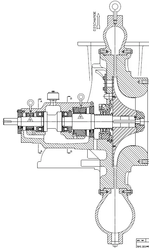
Fig.35 Overhung compressor
The configuration of the bearing upgrade is a Flexure Pivot tilting pad bearing for the coupling end and a Flexure Pivot with ISFD at the impeller end bearing.The Flexure Pivot tilting pad bearing in herently eliminates pivot wear so that the preload and bearing clearance are maintained throughout the bearing operating cycle.The integral squeeze film damper that is part of the impeller end bearing can reduce the amplification factor and shift or critically damp any of the critical speeds within the operating speed range.Fig.38 shows the unbalance response at the coupling end for the existing bearing with pivot wear effects compared to the upgrade bearing.The unbalance response of the OEM rocker back tilting pad bearing is high due to improperly designed and goes worse with pivot wear,as observed in Fig.36.The upgrade Flexure Pivot tilting pad bearings with a 60% offset and a slightly tight clearance for higher stiffness,as on show in Fig.37,is able to reduce the unbalance dramatically.Moreover,the Flexure Pivot bearings do not have pivot wear,so the vibration level remains at a low level over time.The end user recently expressed amazement at the performance of the Flexure Pivot bearing upgrade.
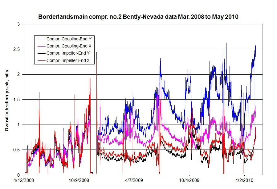
Fig.36 Vibration increase over time(2 year period)due to pivot wear
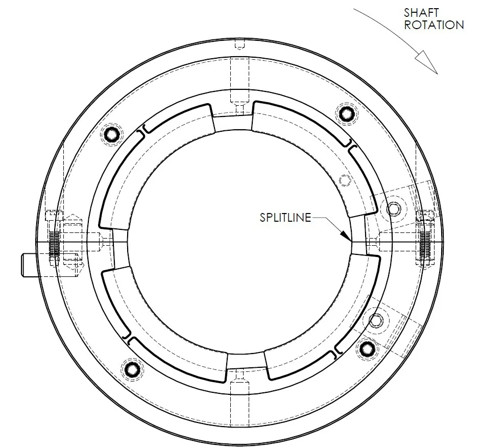
Fig.37 FPJ bearing for coupling end bearing

Fig.38 Unbalance comparison at coupling end bearing
6 Conclusions
Bearing upgrade technology is critical for reliable operation of turbomachinery.Bearing temperature issues can be managed through a compreshensive understanding of the heat balance around the bearing.Similarly,vibration issues can be resolved through an understanding of rotordynamic and bearing fundamentals,along with advanced bearing technology.Countless field reliability issues in turbomachinery were able to be resolved through bearing upgrade technology at author’s company.
7 Acknowledgements
The author wishes to thank Waukesha Bearings Corporation ™for permission to publish this material and Krista Betts and Barry Blair of Waukesha Bearings for their reviews and corrections on the this paper.
- 风机技术的其它文章
- Study of Compressor Stall Margin Enhancement Using Tip Air Injection
- 车用空压机蜗壳优化设计研究
- 动/静干涉对多级离心压缩机整体式静叶片特性影响研究
- 基于流线曲率法的轴流ORC膨胀机反设计*
- Reduction of Hot Oil Carry-over in High Speed Running Turbo Application Bearings
- Foil Bearing Technology for High Speed Single Stage Air Compressors for Fuel Cell Applications

