Study of Compressor Stall Margin Enhancement Using Tip Air Injection
Jie Xu Hong Yan
(1.AECC Hunan Aviation of Powerplant Research Institute;2.School of Power and Energy,Northwestern Polytechnical University)
Abstract:The mechanism of compressor stall margin enhancement using the tip air injection is explored.The transonic compressor,NASA Rotor 37,is taken as the object to study the tip clearance flow under active control of tip air injection by numerical simulations.The effects of injection parameters (injection total temperature,injection position,injection angle,injection mass flow,injection port size,injection type and etc)on the stall margin extension are emphatically analyzed.Results show that the enhancement of tip leakage vortex enlarges the low-energy region induced by the shock wave in the row channel when the working condition is moving to stall point.In addition,the enhancement of radial vortex increases its entrainment ability,which tends to expand separation zone.Once the tip injection imposed,the decrease of the leakage vortex intensity widens the stall margin,while the total pressure loss increases to some extent due to the mixing of the tip micro jet with the mainstream.It is found that injection parameters should be restricted to a moderate region so as to achieve a good stall margin extension without an excessive increase in thepressure loss.
Keywords:Stall Margin;Tip Clearance Flow;Tip Injection;Flow Control;Numerical Simulation
Nomenclature
pstatic pressure
Vvelocity
xradial direction
ycircumferential direction
zaxial direction
ρdensity
0 Introduction
The flow field in the compressor is extremely complicated due to the viscosity and compressibility of the fluid,the three-dimensionality and the non-stationarity.The secondary flow structure,shock wave structure and the interaction between shock wave and boundary layer make it difficult to study the internal flow of compressor.Wisler[1] described the complex flow structure of the transonic compressor.There are mainly passage vortex,tip leakage vortex,wake vortex and corner vortex in the cascade passage.The flow loss generated in the end wall region contributes more than 1/3 of the total loss of the cascade channel,in which the loss caused by the tip leakage vortex takes up a large proportion.At the top of the blade,the pressure difference between the pressure surface and the suction surface forces a portion of fluid to form the tip clearance flow over the blade tip,which is also known as the tip leakage flow.The leakage flow interacts with the mainstream to form the tip leakage vortex.The three-dimensional viscous flow is influenced by the interference of the mainstream and other secondary flow,the boundary layer of the blade surface,the boundary layer of the end wall and the upstream and downstream adjacent blade rows,which makes its characteristics rather complicated.
A series of researches have been carried out on the characteristics of the tip leakage flow,especially the relationship with compressor stall.Furukawa[2]proposed that in the compressor rotor,the tip leakage vortex is more likely to break up under the condition of smaller flow rate,resulting in stronger turbulence fluctuation,which reduced the rotor performance rapidly near stall.Mailach et al[3]put forward that tip leakage vortex is the main factor leading to rotating stall by the analysis of the correlation mechanism between axial compressor stall and tip leakage flow.Vo et al[4]and Hah[5]et al studied the low speed and transonic axial compressor respectively.They proposed that the tip leakage flow plays a decisive role in the triggering process of the peak rotating stall.The criteria for determining the peak stall are as follows:the tip leakage flow refluxes at the trailing edge of the adjacent row channel;at the same time,the interface of the leakage flow and the mainstream exactly aligns to the leading edge of the rotor blade.Numerous studies on the tip leakage flow and compressor stall indicate that the tip leakage flow is closely related to the compressor working performance and the stall margin.The main effect of tip leakage flow on compressor is flow loss and flow blockage,of which the former reduces the compressor efficiency[6] and the latter reduces the total pressure ratio and the stall margin[7].Thus,it's important to take control of the compressor tip leakage flow.
As one of the active control methods of tip leakage flow,tip air injection affects the tip clearance flow field by injecting micro air into the rotor tip region,which is able to expand the stall margin.Compared with the traditional casing treatment,It can improve stall margin on the premise of slightly decreasing the compressor adiabatic efficiency.Day[8] proved by experiment that the tip jet could improve the stall margin of the rotor.Suder et al[9] proposed that the improvement effect of the tip injection on the axial compressor stall margin is related to the jet nozzle number and the jet velocity.Hiller et al[10] verified the theory of Suder by the experiment research on the multistage compressor.
The present study is focused on exploring the mechanism of stall margin extension due to the tip air injection by numerical simulation.The effect of tip injection parameters on the stall margin extension is emphatically analyzed,which provides a new point of view for the optimization of tip injection parameters.
1 Results and Discussion
The internal field of Rotor 37,a typical product of advanced inlet compressor stage design,is calculated without tip injection imposed.
When the axial compressor rotating speed is constant and the flow rate decreases,the incidence of the rotor blade increases correspondingly,which is likely to cause the flow separation.The compressor tends to enter the rotating stall state due to the flow blockage,deteriorating the performance of the compressor obviously.The stall type of Rotor 37 belongs to tip stall,indicating that it's necessary to investigate the structure characteristics of the clearance flow in the blade tip region and analyze its effect on the compressor performance.The streamlines in the tip region under the reference condition and the near stall condition are shown in Fig.1 and Fig.2.The leakage flow at the leading edge of the blade forms the leakage vortex,which is the boundary between the leakage flow and the mainstream.In the developing process downstream,the leakage vortex continuously diffuses,entraining the surrounding fluid and gradually deflecting to the pressure side.Its velocity decreases rapidly after the shock surface in the row channel.The leakage flow at the back of the blade overflows from the pressure side into the adjacent channel,then gets involved in the leakage vortex.The comparison of the clearance flow field under two conditions shows that when the compressor approaches the stall condition,the leakage vortex's entrainment effect is much more intense,and its velocity after the shock wave becomes lower.The leakage flow gets closer to the pressure side in the downstream and even overflows into the adjacent row near the trailing edge.
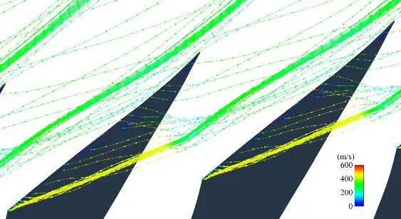
Fig.1 Tip streamline of reference point
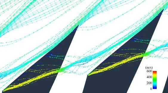
Fig.2 Tip streamline of near stall point
When the radial vortex in the row channel develops to the tip region,it also affects the flow field of the tip clearance.The radial vortex lines in the blade tip region under the reference condition and the near stall condition are shown in Fig.3 and Fig.4.In the development process of the radial vortex,it continuously diffuses,entraining a portion of lowenergy fluid in the separation zone.When the radial vortex reaches the tip region,it's transformed into axial flow due to the obstruction of the casing and then forms the separation vortex with the action of the leakage flow at the trailing edge and the boundary layer of the casing wall.The comparison of the radial vortex development under two conditions shows that when the compressor approaches the stall condition,the axial position of the radial vortex moves forward slightly and its structure still remains intact in the tip region,which indicates that the intensity of the radial vortex increases significantly.The radial vortex breaks up violently at the tip of the blade,and the affected area by the radial vortex gets enlarged accordingly.

Fig.3 Radial vortex of reference point
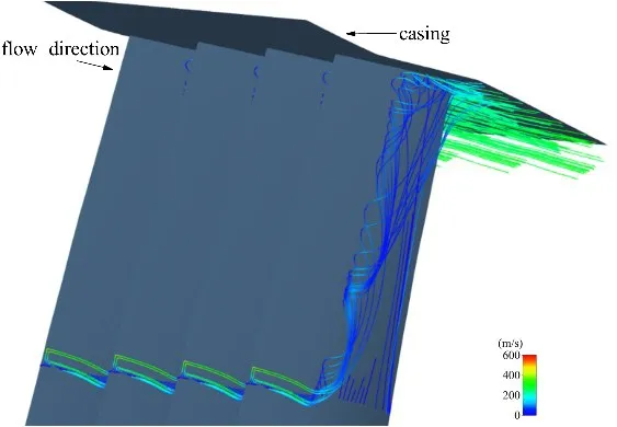
Fig.4 Radial vortex of near stall point
The parameter directly reflecting the vortex intensity is vorticity.The vorticity distribution in the tip region under the reference condition and the near stall condition is respectively shown in Fig.5 and Fig.6.The main concentration of the strong vorticity is on the suction side.The vorticity in the rear part of the channel is mainly caused by the radial vortex,while the vorticity near the leading edge is caused by the leakage vortex.At the initial stage of the development of the leakage vortex,the vorticity is relatively large.With the vortex diffusing,the vorticity density gradually decreases.When the work condition is approaching the stall point,the distribution of the vorticity reveals that the leakage vortex gets stronger and still remains a certain intensity after passing through the shock wave;the intensity of the radial vortex increases and its position is shifted forward.It's noted that according to the distribution characteristics of the leakage flow streamlines in the tip region,the leakage flow owns relatively large vorticity in the front part of the chord.This part of the leakage flow overflows to the suction side and interacts with the radial vortex,which strengthens the vorticity in this region and makes the affecting range of the vorticity extend forward.It's confirmed by the asymmetric distribution of the radial vorticity in Fig.6.
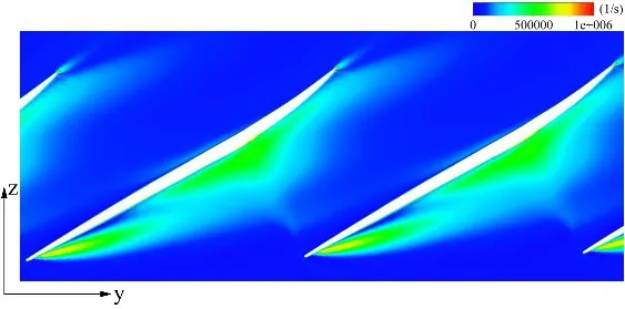
Fig.5 Vorticity distribution at 99%blade height of reference point
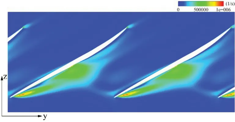
Fig.6 Vorticity distribution at 99%blade height of near stall point
The driving force of the formation of the tip leakage flow is the tip load:the pressure difference between the pressure side and the suction side in the tip region.The tip load at the position of 99%blade height under the reference condition and the near stall condition is shown in Fig.7.Under both conditions,the tip load is the largest at the leading edge.The tip load of the near stall point is higher than that of the reference point in the front part of the chord,while in the rear part the difference of the tip load is relatively small.Since the leakage flow forming in the front part of the total vorticity,the effect of the tip load in the rear part of the chord on the leakage flow could be neglected.All in all,the pressure difference close to the leading edge increases when the work condition is approaching the stall point,of which the tendency is consistent with that of the intensity of the leakage vortex.
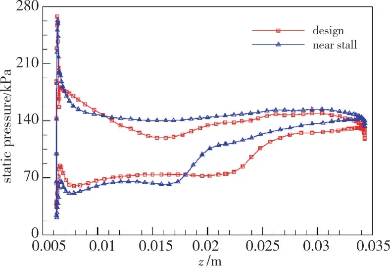
Fig.7 Tip load distribution at 99%blade height
Based on the velocity distribution of the fluid in the tip region,the effect of the tip clearance flow on the channel blockage is analyzed.The distribution of Mach number at the middle and the top region of the blade under the reference condition is shown in Fig.8 and Fig.9.Since the blade angle at the middle of the blade is greater than that at the top of the blade,the flow separation at the former position is more serious than that at the latter position.The Mach number of the leakage vortex forming at the leading edge is smaller than that of the mainstream.The leakage flow forms the low-energy zone after passing through the shock wave.The distribution of Mach number at the middle and the top region of the blade under the near stall condition is shown in Fig.10 and Fig.11.The comparison between Fig.8 and Fig.10 shows that the shock wave in the channel slightly shifts upstream,and the separation zone on the suction side moves slightly towards the leading edge under the combined effect of the enhancement of the radial vortex and the increase of the back pressure,which indicates that the increase of the back pressure has only limited effect on the flow field.In order to study the effect of the leakage flow on the field,the comparison is made between Fig.9 and Fig.11.The interaction between the leakage vortex and the shock wave after the increase of the vorticity makes the shock wave deflect to the leading edge.There forms the low-energy zone of lower velocity and larger area after the shock wave than that under the reference work condition.In the rear region on the suction side,the intensity of the radial vortex increases and the vortex moves forward,which results in the violent breakdown in the tip region and produces a large area of blockage.
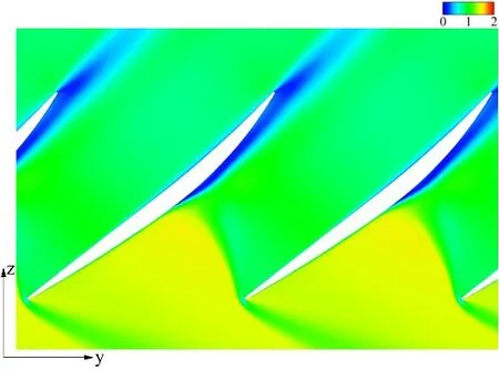
Fig.8 Mach number distribution at 50%blade height of reference point
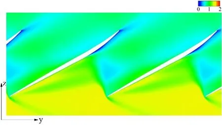
Fig.9 Mach number distribution at 99%blade height of reference point

Fig.10 Mach number distribution at 50%blade height of near stall point
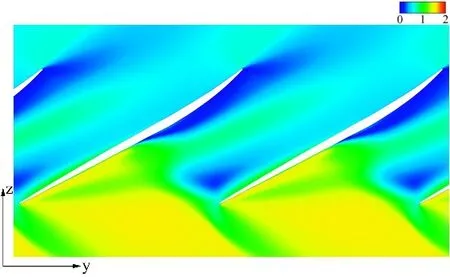
Fig.11 Mach number distribution at 99%blade height of near stall point
Vortex is formed by the transformation of the airflow mechanical energy,leading to the flow loss.The level of flow loss is generally measured by the total pressure loss coefficient,which is defined as:

whererepresents the relative total pressure of the fluid at the inlet.With five sections(z/c=0,0.25,0.5,0.75,1) along the flow direction selected,the distribution of the total loss coefficient under the reference and the near stall condition is shown in Fig.12 and Fig.13.The pressure loss includes the friction loss caused by the interaction with the wall and the flow loss caused by the secondary flow,in which the former could be neglected compared to the latter.The level of flow loss is positively correlated with the vorticty.The position of the maximum pressure loss is corresponding to the location of the leakage vortex core.During the downstream development of the leakage vortex,the maximal value of the pressure loss on the sections first increases and then decreases,with the coverage area of the loss expanding both in the circumferential and radial direction.When the stall point is nearly approaching,the leakage vortex inclines towards the inlet,of which the increase of the intensity raises the pressure loss accordingly.The position of the maximum loss moves towards the pressure side.That the radial vortex shifts forwards and its intensity increases makes the level of the flow loss increase and the location of the maximum loss shift forward.
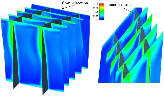
Fig.12 Distribution of total pressure loss coefficient of reference point
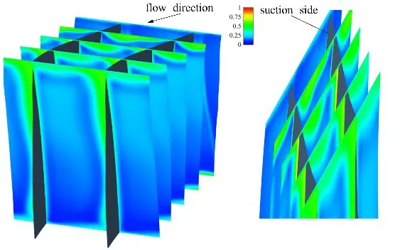
Fig.13 Distribution of total pressure loss coefficient of near stall point
The distribution of the mean flow loss of each section along the flow direction is investigated as shown in Fig.14 since the leakage vortex diffuses with its intensity decreasing.The flow loss in the tip region accounts for the main part of the total loss of the channel.The level of the flow loss of the channel increases in flow direction,of which the rate declines continuously,which suggests that in the region of strong leakage vortex and radial vortex,the flow loss of the field increases rapidly,while in the downstream,the effect of the diffusing vortex on the pressure loss decreases gradually,confirming the positive correlation between the vortex intensity and the total pressure loss.
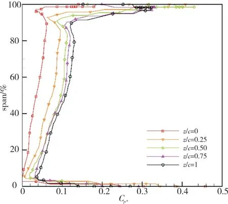
Fig.14 Radial distribution of total pressure loss coefficient on each section
Based on the relationship between the tip clearance flow and the compressor stall,the effect of the tip air injection on the stall margin is investigated so as to explore the mechanism of the effects of difference injection conditions on the compressor stall margin:1) jet style:full-cycle slot,8 circumferential uniform jet points,18 circumferential uniform jet points,36 circumferential uniform jet points;2) jet flow:0.01kg/s,0.02kg/s,0.04kg/s,respectively corresponding to 0.05%,0.1%,0.2%of the design flow;3)jet temperature:200K,300K,400K;4) jet position:1 time the axial tip chord upstream of the leading edge,0.5 times the axial tip chord upstream of the leading edge,the leading edge,the middle of the tip chord;5)jet angle:deflection is set as 0°,±10°,±20°along the circumferential direction.
To facilitate the expression,the work condition of difference parameters is simplified as a symbolic representation.For example,the work condition named“36P_10.5c200K10y-10”represents that 36P1 means 36 jet nozzles are uniformly distributed along the cycle,the total jet flow rate is 0.1% of the design inlet flow rate,which is expressed as P1 if the slot jet is applied;0.5c means the axial location of the jet is 0.5 times tip chord upstream from the leading edge,200K means the jet total temperature,10 means the jet nozzle diameter is 1.0mm,y-10 means the angle between the jet direction and y axis is-10°.
The variation of the stall margin is defined as:

whereSM0andSM1respectively represents the stall margin under the condition without air injection and with air injection,considering the effect of the flow rate and the pressure ratio.The numerical simulation of the flow field of Rotor 37 under different injection conditions by adjusting injection parameters results in the stall margin and its improvement of each work condition,which are shown in Tab.1.

Tab.1 Stall margin and improvement under different conditions
As shown in the table above,different injection parameters selection results in different working range of the compressor.The effect of the interaction of two or more parameters is neglected,which means only a single parameter is studied during each investigation.The effect of each parameter on the stall margin is as follows:
1)Injection total temperature
The comparison of case 2~4 shows that the improvement of the stall margin is higher if the injection total temperature is lower.
2)Injection position
The comparison of case 2,5~7 shows that the maximum improvement of the stall margin could be reached if the injection nozzle is located about 0.5 times tip chord upstream from the leading edge,while injection at the leading edge results in the lowest stall margin.
3)Injection angle
The comparison of case 2,8~11 shows that moderate prewhirl angle of the injected flow leads to a high improvement of the stall margin,while a excessive angle could be counter-productive.
4)Injection flow rate
The comparison of case 2,12 and 13 shows that only the moderate injection flow rate results in a good improvement of the stall margin.
5)Injection nozzle size
The comparison of case 2,14 and 15 shows that if the injection nozzle is oversize,the operation state of the compressor gets worsened and the work range narrows.
6)Injection type
The comparison of case 2 and 16 shows that under the condition of the same total flow rate of the air injection,the injection in the form of circumferential distributed points leads to a better improvement effect on the stall margin than that in the form of full-cycle slot;The comparison of Case 2,18 and 19 shows that under the condition of the same total jet flow rate,reducing the number of injection nozzle appropriately could slightly improve the stall margin;The comparison of Case 2,18 and 19 shows that under the condition of the same flow rate of each single nozzle,the reduction of the nozzle number results in a significant decrease of the stall margin.
The numerical simulation results show that the compressor stall margin could be improved to some extent by adopting appropriate injection parameters.Based on the relative rules obtained above,the internal mechanism of the improvement of the rotor aerodynamic performance is analyzed according to the change of the flow field before and after air injection.It's noted that during the analysis of the flow field,the back pressure under the two conditions should be kept the same so as to rule out the influence of the vortex with different intensity caused by the variation of the back pressure.What's more,for the sake of visualization,the flow field with the vortex of a relatively strong intensity before and after the air injection is chosen as the object of study.
As the standard operating condition,the case named“36P1_0.5c200K10y0”is used for the comparative analysis under the condition without air injection and with air injection.The working characteristics before and after the tip jet is injected are shown in Fig.15 and Fig.16.After the micro tip jet is imposed,the stall flow is relatively lower compared to that under the condition without air injection,while the efficiency and the total pressure on the whole characteristics line is slightly lower than that under the condition without air injection.
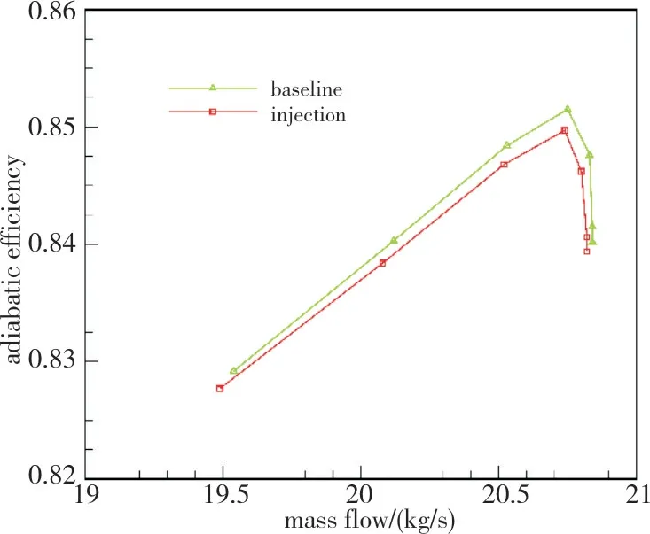
Fig.15 Efficiency characteristics without/with injection

Fig.16 Pressure ratio characteristics without/with injection
The difference of the internal flow field is analyzed to explore the mechanism of the effect of the tip injection on the compressor performance.The change of the structural characteristics of the tip clearance flow under the condition without air injection and with air injection is firstly studied,as shown in Fig.17 and Fig.18.After the injection is imposed,the velocity of the leakage flow at the leading edge reduces,making the leakage vortex lack of intensity.The entrainment ability of the leakage vortex in the downstream development is relatively weaker and the amount of leakage at the trailing edge is lower than those of the non-injection condition.A portion of leakage flow produced in the middle part of the chord tends to keep moving after passing through the leakage vortex and then overflows to the next row channel.It's obtained from the rules above that the tip injection leads to the decrease of the intensity of the tip leakage vortex and accordingly reduces the flow loss;The decrease of the amount of the leakage flow overflowing from the rear part of the chord indicates that the leakage flow with a certain circumferential velocity lessens,which narrows the range of the separation zone and reduces the channel blockage.These two changes both contribute to the improvement of the working range of the rotor.However,it's essential to consider the effect of the mixing loss between the injected jet and the mainstream on the rotor working performance.
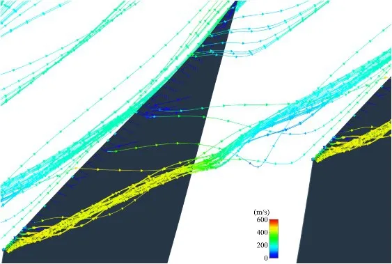
Fig.17 Tip streamline without injection

Fig.18 Tip streamline with injection
The vorticity distribution in the tip region under the condition without air injection and with air injection is shown in Fig.19 and Fig.20.The micro jet imposed at the top of the blade mixes with the mainstream,forming a certain intensity of vortex at the location of the injection nozzle.It's noted that the vortex at the nozzle inlet exists on the whole characteristics line,which means it's the total performance in the working range of the rotor that gets affected.The presentation of the effect is the global shifting down of the characteristics line rather than the appearance of the vortex merely under the near stall condition.The comparison of the two figures shows that once the tip jet imposed,the intensity of the leakage vortex at the leading edge decreases significantly and the size of the radial vortex in the middle part of the chord reduces by a certain degree,suggesting that the tip injection suppresses the formation of the vortex in the row channel downstream.

Fig.19 Vorticity at 99%blade height without injection

Fig.20 Vorticity at 99%blade height with injection
The static pressure distribution on the pressure and the suction surface of the tip before and after the tip injection is imposed is shown in Fig.21.The tip load close to the leading edge of the injection condition decreases by a certain degree compared to that of the non-injection condition,while the difference is indistinct in the rear part of the chord,which indicates that the mixing between the tip injection and the mainstream is able to reduce the tip load at the inlet of the row channel and decrease the amount of leakage and the intensity of the leakage vortex.
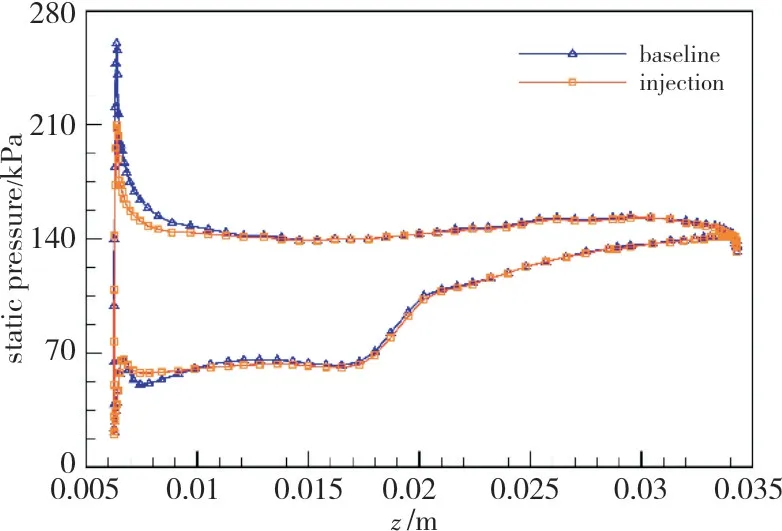
Fig.21 Tip load at 99%blade height without/with injection
The circumferential velocity of the fluid in the tip region under the non-injection and injection condition is observed to investigate the blockage condition of the channel,as shown in Fig.22 and Fig.23.The interaction between the tip micro jet and the overhanging shock wave decreases the circumferential velocity of the fluid in the row channel and reduces the intensity of the leakage vortex,which results in that the circumferential velocity of the fluid after the shock wave gets distinctly lower than that under the non-injection condition,representing the blockage is weakened compared to the non-injection condition.
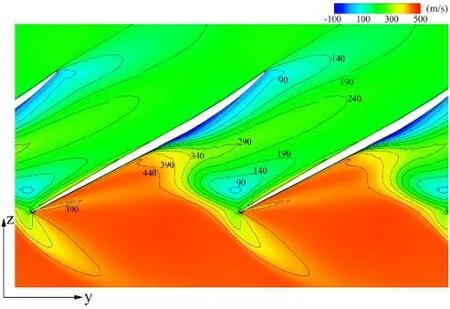
Fig.22 Circumferential velocity component without injection

Fig.23 Circumferential velocity component with injection
To explore the affecting area of the total pressure loss with the tip injection imposed in the axial and the circumferential direction,the axial distribution curve of the total pressure loss coefficient at different radial positions of the blade under the non-injection and injection condition close to the stall point is shown in Fig.24,in which the leading edge of the blade locates atz=0.0064m,the trailing edge locates atz=0.0343m,the injection nozzle locates atz=0.0074m.The analysis shows:
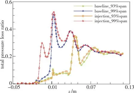
Fig.24 Axial distribution of pressure loss coefficient at different radial position
1) The comparison between the distribution of the total pressure loss coefficient at the position of 93% and 99%blade height under the non-injection condition shows that,the mean pressure loss of the latter in the channel region is much higher than that of the former.It's noted that the tip total pressure loss is due to the comprehensive effect of the wall friction,leakage vortex and the separation zone.The maximum loss coefficient in the region at the position of 99% is 0.5,which is considerably larger than 0.1,the maximum value at the position of 93%;The violent breakdown of the radial vortex in the tip region and the mixing effect of the leakage flow in the middle part of the chord make the loss coefficient curve in the rear part of the chord at the position of 99% shift upward overall compared to that at the position of 93%and the peak value of the loss coefficient increase slightly.It suggests that the extra total pressure loss caused by the tip clearance flow mainly concentrates in the tip region along the radial direction and in the row channel along the axial direction,locating where the leakage vortex and the radial vortex is relatively strong;The extra pressure loss mainly comes from the effect of the leakage vortex,the loss degree from which is much higher than that from wall friction.
2) The comparison between the distribution of the total pressure loss coefficient at the same radial position under the non-injection and the injection condition shows that,at the position of 93% blade height,the loss coefficient curve under the injection condition almost coincides with that under the non-injection condition.While at the position of 99%blade height,the total loss under the injection condition is significantly higher than that under the non-injection condition upstream the leading edge,and reaches the peak value 0.3 at the position of the injection nozzle inlet.The loss under the injection condition is also higher than that under the non-injection condition in the middle part of the chord.The difference of the peak value under the two conditions is invisible in the affecting area of leakage vortex and radial vortex.It indicates that the total pressure loss caused by the mixing between the tip jet and the mainstream mainly concentrates in the tip region along the radial direction and in the region between the nozzle inlet and the leading edge along the axial direction.
The determination of the compressor working range depends on the total pressure loss of the reference point and the near stall point,calling for investigating the level of the total pressure loss under the condition with the different back pressure.The comparison of the total loss at the position of 99%blade height under the condition with the same back pressure before and after the tip injection is imposed is shown in Fig.25.The analysis shows:
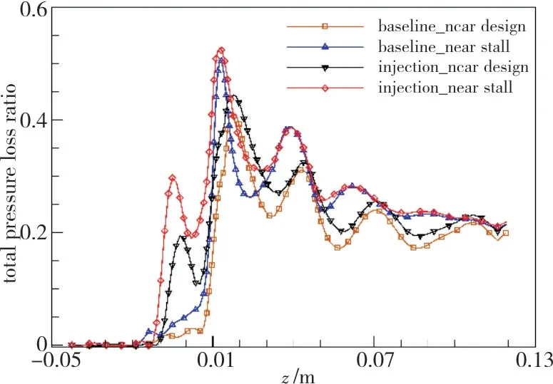
Fig.25 Axial distribution of pressure loss coefficient under different back pressure
1) The comparison between the distribution of the total pressure loss coefficient of the reference point and the near stall point in the tip field under the non-injection condition shows that,when the stall point is approaching,the pressure loss is relatively higher at the leading edge compared to that of the reference point.That the leakage vortex gets stronger and deflects towards the inlet makes the loss curve in the front part of the chord move forward and its peak value increase obviously.That the radial vortex shifts forward and strengthens on the suction side makes the loss curve at the trailing edge and downstream moves upward overall and its peak value in the separation zone significantly increase.It suggests that with the back pressure increasing,the vorticity of the tip clearance flow gets larger and the pressure loss of the tip field increases accordingly,leading to the compressor approaching the stall state.
2) The comparison between the distribution of the total pressure loss coefficient under the non-injection and injection condition with the same back pressure shows that,the tip injection results in the pressure loss increasing by different degree downstream the jet nozzle inlet under both conditions,of which the increment is relatively large in the region between the nozzle inlet and row channel inlet and relatively small downstream the leading edge.The comparison between the increment of the pressure loss of the reference point and the near stall point shows that,in the affecting region of the leakage vortex besides the downstream,the increment of the pressure loss of the near stall point is smaller than that of the reference point,while in the region between the nozzle inlet and the channel inlet,the increment of the pressure loss is slightly larger than that of the reference point.It indicates that the vorticity produced by the mixing between the imposed tip jet and the mainstream makes the pressure loss of the compressor increase slightly,which is reflected as the whole pressure ratio curve shifting downward slightly.However,due to the mixing between the tip jet and the mainstream,the leakage vortex in the channel weakens and the amount of leakage lessens,resulting in that under the injection condition,the increment of the pressure loss under the injection condition caused by the leakage flow is lower than that under the non-injection condition,which plays a positive role in improving the pressure ratio margin.Under the present injection condition,the tip jet could lessen the increment of the total pressure loss and reduce the channel blockage,the effect of which overweighs that of the mixing loss advancing the stall.The compressor working range expands at the expense of weakening the pressure rising capacity.
According to the mechanism of the stall margin enhancement by the tip injection above,the reason for the difference of the enhancement effect caused by the variation of the injection parameters is investigated,on which the optimization direction of the injection parameters is based.For the sake of visualization,the distribution curves of the tip load and the total pressure loss coefficient are used to study the change of the flow field after the injection parameters changes.Similarly,the comparison should be operated under the condition with the same back pressure.
1)Injection total temperature
The total temperature at the injection nozzle inlet is set as 200K,300K and 400K.The distribution of the tip load with different injection total temperature is shown in Fig.26.The comparison of the static pressure curves shows that,when the total temperature increases,the tip load reduces slightly,but its decrement is relatively quite low compared to that under the non-injection condition.There is the positive correlation between the tip load and the intensity of the leakage vortex,indicating that the increase of the temperature makes the intensity of the leakage vortex reduce slightly.

Fig.26 Tip load with different injection total temperature
The axial distribution curve of the circumferentially mean total pressure loss coefficient under the reference and the near stall condition with different injection total temperature is shown in Fig.27.When the total temperature increases,the pressure loss caused by the mixing between the tip jet and the mainstream gets higher,which is because the heating effect of the jet with higher total temperature on the mainstream increases and thus the thermal resistance gets greater,further reducing the flow total pressure.It's noted that the increment of the pressure loss under the near stall condition is larger than that under the reference condition,which means the increase of the jet total temperature reduces the pressure ratio margin at the same time of increasing the flow loss.The comparison of the margin improvement of case 2~4 in Tab.1 shows that,the margin improvement is the worst when the injection total temperature is 400K,which indicates the effect of the loss increment caused by the increase of the temperature on the stall margin is greater than that of the decrement of the leakage vortex.The analysis suggests that the injection total temperature should be as low as possible in order to obtain a wider working range at the same time of reducing the total pressure loss.
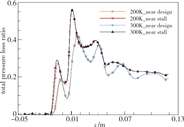
Fig.27 Total pressure loss coefficient with different injection total temperature
2)Injection position
The axial position of the injection nozzle inlet is set 1,0.5,0 and-0.5 times tip chord upstream the leading edge,the corresponding axial coordinate is:z=-0.022m,-0.0074m,0.0061m and 0.0192m.The tip load distribution with different injection positions is shown in Fig.28.The comparison of the static pressure curves shows that,the tip load decrement close to the leading edge is the greatest if the injection nozzle inlet is placed 0.5 times tip chord upstream the leading edge,while the effect of injection at the leading edge is inferior to that upstream the leading edge,which indicates that the injection nozzle inlet should be located appropriate distance upstream from the leading edge.When the distance is too long,the effect of the mixing between the injected jet and the mainstream weakens;if too short,the micro jet is not able to affect the whole field in the circumferential direction.The injection imposed at the middle of the chord affects the load near the nozzle inlet,making the load increase first and then decrease along the axial direction.The load at the leading edge is the highest in several conditions for it's not affected by the tip jet.
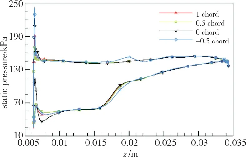
Fig.28 Tip load with different injection position
The axial distribution curve of the total pressure loss coefficient with different positions of the injection nozzle inlet is shown in Fig.29.The injection at the leading edge leads to the whole loss coefficient curve moving upward compared to that upstream the leading edge,and the peak value of the curve in the front part of the chord increases and its position shifts forwards slightly.The injection at the middle of the chord also affects the flow loss upstream the nozzle inlet,which is reflected as that the peak value of the loss coefficient curve increases and the loss in the rear part of the chord decreases.The total pressure loss at the rotor outlet is the lowest in several conditions.The comparison shows that the better-to-worse order of the margin improvement is:0.5c,c,-0.5c,0c upstream from the leading edge,indicating that when the injection changes,the main factor affecting the stall margin is the intensity of the leakage vortex at the leading edge.Placing the injection nozzle inlet about 0.5 times tip chord upstream from the leading edge tends to result in relatively good margin improvement.
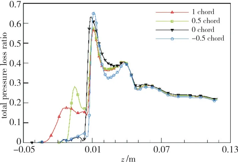
Fig.29 Total pressure loss coefficient with different injection position
3)Injection angle
The injection angle is set as 0°,±10° and ±20°,where the angle being negative is named as the positive prewhirl,indicating the deflection of the tip jet and the rotating direction of the rotor is the same.The tip load distribution in the front part of the chord with different injection angles is shown in Fig.30,where the static pressure curves near the leading edge are amplified for display and the difference of pressure is neglected.The analysis shows that,compared to the negative prewhirl and zero prewhirl,the positive prewhirl leads to the lower capacity to weaken the tip load,while the difference is relatively small.The axial distribution of the total pressure loss coefficient with different injection angles under the reference and the near stall condition is shown in Fig.31.Compared to zero prewhirl,the injection with ±10° positive prewhirl results in the mixing loss between the tip jet and the mainstream reducing,while the negative prewhirl makes the loss increase.It's because when the positive prewhirl is adopted,the circumferential component of the relative velocity at the channel inlet reduces,which suppresses the formation of separation zone in the row channel and decreases the flow loss to some extent.The comparison of case 2,8~11 shows that the better-to-worse order of the margin improvement is:10° positive prewhirl,10° negative prewhirl,20° negative prewhirl,zero prewhirl and 20°positive prewhirl,indicating that the effect of the pressure loss decrement caused by the positive prewhirl with a small angle on the stall margin is greater than that of the intensity decrement of the leakage vortex.If the prewhirl angle is oversize,the axial velocity component of the imposed jet gets further lower,weakening the effect on the flow field downstream and worsening the margin improvement.The analysis above suggests that the injection angle is supposed to be set as about 10° positive prewhirl in order to guarantee the extra flow loss caused by the injection relatively low at the same time of improving the stall margin of the compressor.

Fig.30 Tip load with different injection angle
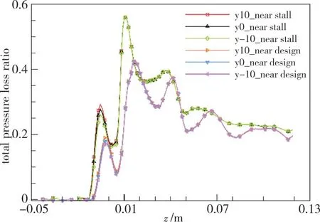
Fig.31 Total pressure loss coefficient with different injection angle
4)Injection flow rate
The total injection flow rate is set as 0.05%,0.1% and 0.2% of the rotor design flow rate.It's noted that the total flow rate changes while the injection nozzle size remains the same,accordingly the jet velocity changes.The coupled relationship between the three parameters calls for the comprehensive consideration when choosing the best injection condition.The tip load distribution with different total injection flow rate is shown in Fig.32.The increase of the injection flow rate leads to the tip load at the leading edge weakening.The axial distribution of the total pressure loss coefficient with different total injection flow rate is shown in Fig.33.When the injection flow rate gets higher,the mixing loss between the tip jet and the mainstream increases rapidly,worsening the pressure rising capacity.The comparison of case 2,12 and 13 shows that,when the injection flow rate is 0.05%and 0.2%,the corresponding stall margin is lower than that under the non-injection condition.It's because if the injection flow rate is oversize,the effect of the decrement of the pressure ratio margin caused by the flow loss is greater than that of the intensity decrement of the leakage vortex.If the injection flow rate is too small,the suppressing effect on the intensity of the leakage vortex insufficient,which can hardly offset the effect of the mixing loss due to the imposed injection on the compressor working range.The above analysis suggests that the injection total flow rate is supposed to be set as about 0.1% of the rotor design flow rate so as to control the pressure loss in a certain degree and effectively suppress the intensity of the leakage vortex,which promotes the improvement of the stall margin.
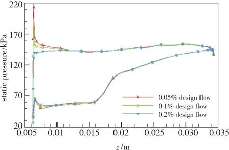
Fig.32 Tip load with different injection flow rate

Fig.33 Total pressure loss coefficient with different injection flow rate
5)Injection nozzle size
The injection nozzle size is set as 1mm,2mm and 3mm.The tip load distribution with different injection nozzle size is shown in Fig.34.If the nozzle size is relatively small,the change of the tip load is correspondingly small.When the nozzle size increases to some extent,the tip load at the leading edge further reduces compared to that with a small-sized nozzle.The axial distribution of the total pressure loss coefficient with different total injection flow rate is shown in Fig.35.When the diameter of the injection nozzle increases,the pressure loss does not monotonously vary.The peak value of the pressure loss curve is the lowest when the nozzle diameter is 2mm.When the nozzle diameter increases to 3mm,there appears flow loss in a large region upstream the leading edge,which is because under the condition with small-sized nozzle,the increase of the nozzle diameter makes the injection velocity reduce rapidly,weakening the mixing loss with the mainstream.When the nozzle size increases to a certain extent,the contact area between the imposed jet and the mainstream is relatively large and the jet velocity is very low,resulting in large areas of flow loss upstream and downstream the nozzle inlet.The comparison of case 2,14 and 15 shows that,if the nozzle size moderate,the margin improvement is the best.Too large or too small nozzle size leads to the flow loss intensifying which suppresses the improvement of the stall margin.The above analysis indicates that the injection nozzle size is supposed to be kept between 1mm and 2mm in order to control the jet velocity relatively low and at the same time,reduce the contact area between the injection nozzle and the mainstream,which realizes the improvement of the stall margin mainly by decreasing the total pressure loss.
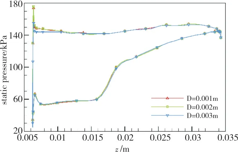
Fig.34 Tip load with different injection nozzle size
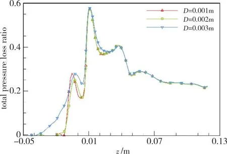
Fig.35 Total pressure loss coefficient with different injection nozzle size
6)Injection type
With the total injection flow rate kept the same,the injection type is set as full-cycle slot,circumferential uniform distribution with 36 points and 18 points.The axial distribution of the tip load and the total pressure loss with different injection types is shown in Fig.36 and Fig.37.The tip load decrement at leading edge with the slot jet type inferior to that with the points jet type.The number of the distributed points less,the decrement of the tip load further lower,which is because the increase of the jet velocity results in higher momentum transmitted into the end-wall boundary layer,weakening the tip load further.However,with the jet velocity increasing,the flow loss is also intensifying which lower the pressure rising capacity of the compressor,as shown in Fig.37.The comparison of case 2,16 and 17 shows that the better-to-worse order of the margin improvement is:18 points,36 points and slot,indicating that with the increase of the jet velocity,the effect of the intensity decrement of the leakage vortex on the stall margin is greater than that of the increment of total pressure loss.The above analysis suggests that with the total injection flow rate kept the same,it's supposed to select the injection type of circumferential distributed points with moderate nozzle numbers in order to control the pressure loss of the channel relatively low at the same of suppress the intensity of leakage vortex and improve the stall margin.
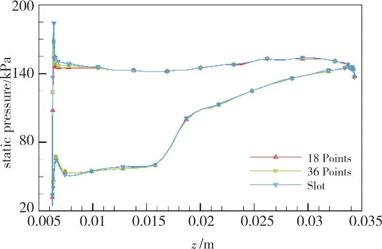
Fig.36 Tip load with different injection type and the same total jet flow
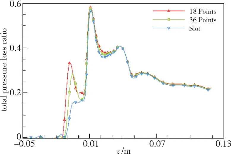
Fig.37 Total pressure loss coefficient with different injection type and the same total jet flow
With the injection type of circumferential distributed points selected,the flow rate of each nozzle inlet is kept the same and the injection points is set as 9,18 and 36.The axial distribution of the tip load and the total pressure loss with the each nozzle flow rate kept the same and different injection points is shown in Fig.38 and Fig.39.With the increase of injection points number,the total injection flow rate accordingly gets higher and the inhibitory effect on the leakage vortex is improved,further weakening the tip load at the leading edge.However,the total pressure loss of the flow field is intensifying correspondingly and the pressure rising capacity reduces.The comparison of case 2,18 and 19 shows that the margin improving effect gets promoted with the increase of the injection points,indicating that with more injection points,the effect of the intensity decrement of the leakage vortex on the stall margin is greater than that of the increment of the total pressure loss.The above analysis shows that when the flow rate at each nozzle inlet is the same,it's supposed to select moderate injection points which guarantee controlling the degree of the pressure loss on the promise of promoting the stall margin.

Fig.38 Tip load with different injection points and the same single jet flow
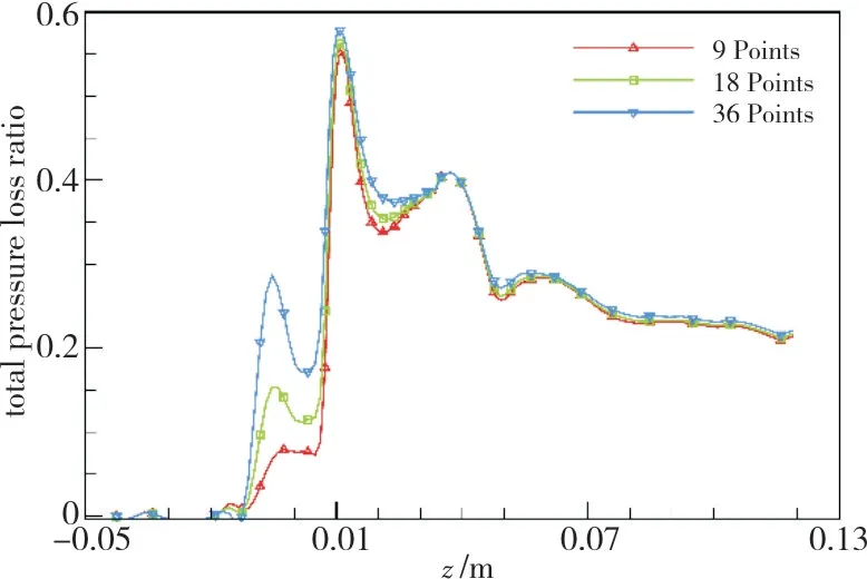
Fig.39 Total pressure loss coefficient with different injection points and the same single jet flow
Considering the coupled relationship between the flow rate,injection nozzle size and the jet velocity,the effect of them on the stall margin improvement and the flow loss is analyzed.When the optimal parameters is to be selected,it calls for comprehensive consideration suppress the total pressure loss at the same time of improving the stall margin:the total injection flow rate is supposed to be within a reasonable range;the injection type of circumferential distributed points is selected and the number of the injection nozzle should be moderate;the injection nozzle diameter also be controlled in a moderate range.The selection of the total injection flow rate and the nozzle size also meets the requirement for the injection velocity at the same time.
2 Conclusions
A three-dimensional numerical study is performed to explore the effect of the tip injection on the tip clearance flow.The flow field in the tip region is emphatically observed to analyze the mechanism of stall margin improvement by tip injection,on which the selection principle for the optimal jet parameters is based.Results show that it's the increase of leakage vortex and radial vortex that both intensify the blockage and flow loss of the row channel contributing on approaching the stall state.After the tip injection is imposed,with the leakage vortex and the radial vortex weakened,the stall margin gets improved despite of the increase of flow loss.The injection parameters are supposed to be controlled in a moderate range so that a balance is able to be reached between the improvement of stall margin and the increase of total pressure loss.
- 风机技术的其它文章
- 车用空压机蜗壳优化设计研究
- 动/静干涉对多级离心压缩机整体式静叶片特性影响研究
- 基于流线曲率法的轴流ORC膨胀机反设计*
- Reliable Operation of Turbomachinery Through Bearing Upgrades
- Reduction of Hot Oil Carry-over in High Speed Running Turbo Application Bearings
- Foil Bearing Technology for High Speed Single Stage Air Compressors for Fuel Cell Applications

