Single pixel imaging based on semi-continuous wavelet transform*
Chao Gao(高超) Xiaoqian Wang(王晓茜) Shuang Wang(王爽) Lidan Gou(苟立丹)Yuling Feng(冯玉玲) Guangyong Jin(金光勇) and Zhihai Yao(姚治海)
1Department of Physics,Changchun University of Science and Technology,Changchun 130022,China
2Jilin Key Laboratory of Solid Laser Technology and Application,Changchun University of Science and Technology,Changchun 130022,China
Keywords: single pixel imaging,wavelet transform,modulation of light source
1. Introduction
Single pixel imaging(SPI)is a novel imaging technique,and its development is strongly related with ghost imaging.[1,2]The efforts of introducing true thermal light into a ghost imaging system[3-6]make ghost imaging easier be realized,which opens a new area and pushed the development of ghost imaging. In 2008,computational ghost imaging is proposed,which allows one to use only a single-pixel detector to obtain the image of the target object. Thus it can be regarded as the beginning of the SPI technique.[7]In an ordinary SPI system, the image of the target object can be obtained using a single-pixel detector and a light source which can create premade illuminations. Such a technique becomes a focus of research because of its advantages: it has high lateral imaging resolution[8-10]and high robustness,[11-15]it could realize imaging with wide spectrum range,[16]furthermore, encryption of image information[17,18]and 3D imaging using the SPI technique are also reported.[19]SPI has great potentials in practical applications. However, it has two shortcomings: its poor imaging quality and speed. For over a decade,in the applications of various reconstruction algorithms[20-22]and different illumination patterns,[23-26]its imaging quality has been significantly improved. The imaging efficiency seems to be the only obstacle which limits the development and the applications of the SPI technique.
The key to improve the imaging speed is to remove unnecessary information during the sampling and/or reconstruction progress. Many works have been carried out in recent years, such as introducing compress sensing theory into an SPI system, which can improve the imaging efficiency.[27,28]As another powerful tool, wavelet theory is developed in the 1980s,different from those“global”transforms(e.g.,Fourier transform), wavelet transform gives more attention to the local information of the signal. By stretching and translating of the wavelets,it can focus on any detail of the signal,and it is widely used in representing signals compressively.
Recent studies about the application of wavelet theory in the SPI system are concentrated on the Haar wavelets,[29-31]these works improved the speed of SPI. However, research about other wavelets are less referred,especially those smooth wavelets.Generally speaking,most of the smooth wavelets are not orthogonal(e.g.,Gauss wavelet,Mexican-hat wavelet,...),they are not able to realize discrete wavelet transform(DWT).Most of the non-orthogonal wavelets can only realize continuous wavelet transforms (CWTs), in which huge numbers of redundant measurements should be performed. This may be the fundamental reasons that smooth wavelets are less mentioned or studied in SPI schemes. However,there are various types of smooth wavelets,they have different features,which may have advantages in representing objects in different types of smoothly changed features with pretty high efficiency, or accurately extract a certain type of features from the object.In this paper, we focus on establishment of a new protocol,i.e.,the semi-continuous wavelet transform(SCWT).The proposed protocol should be something between DWT and CWT,which allows one to use non-orthogonal wavelet sets, keep a high-quality reconstruction and with a moderate (limited)number of measurements at the same time. Most importantly,it should adapt with an SPI scheme.
In Section 2, we propose the SCWT protocol, discuss the contradiction between DWT and CWT when using nonorthogonal wavelet sets. With the example of 1D-Gauss wavelet,the fundamental idea of the SCWT protocol is introduced, and the protocol is verified by numerical simulations.In Section 3, we introduce the SCWT protocol into the SPI system and the scheme is verified experimentally. Furthermore,we discuss the issues that may occur in actual practices.Correspondingly,the solutions are studied and introduced. In Section 4, the compressive reconstruction of Gauss wavelet based SCWT-SPI is studied. A comparison between our proposed scheme and two other existing schemes(i.e.,Hadamard and sinusoidal based single pixel imaging)is given. Using the results,we discuss the effectiveness and efficiency of the proposed SCWT scheme. Finally, in Section 5, we conclude the works of this paper,and further works are also predicted.
2. Semi-continuous wavelet transform
It is not a good choice to perform a discrete wavelet transform(DWT)using a non-orthogonal wavelet set. However,in the SPI system,performing a continuous wavelet transform is another bad choice,we will discuss the reasons. A CWT for a signalf(x)can be defined as

whereais the scaling ratio, andbdenotes the translation of the wavelets. In this case, parametersaandbare continuous variables. For everyaandb,an illumination pattern is needed.Obviously,it is inappropriate for our SPI system because of its unlimited steps of measurements.
Thus,in order to use the property of continuous wavelets and to reduce unnecessary measurements caused by the CWT at the same time,we propose an SCWT based on a DWT.
By scaling the wavelet into different levels, a set of wavelets including different spatial frequencies can be obtained as follows:

For the DWT, parameterais limited to be the integral power of 2. For a mother wavelet defined in interval[-xmax,xmax],bis related witha,

wherer=xmax-(-xmax)=2xmax,which denotes the length of definition interval of the mother wavelet; andm=±1,±2,±3,...,±a/2. Specially, letb=0 ifa=1, which means that there will be no translations when the scale ratio is 1.
Thus, the wavelet set is built. For a 1D signalf(x),the wavelet transform coefficients are the inner product of the wavelets and the signal itself

by calculating the linear superposition of wavelets and corresponding wavelet coefficients, the reconstructed signalF(x)can be obtained as follows:

As mentioned above, for wavelets which are not orthogonal,issues may occur when one tries to reconstruct a signal using them in a DWT way. In order to get a clearer view of this issue,we take Gaussian wavelet as an example,it is the 1st-order derivative of Gaussian function

Figure 1 shows the results of Gaussian wavelet based a DWT for a sine wave and a square wave.
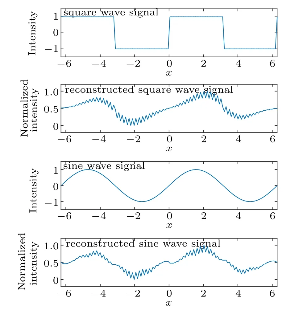
Fig. 1. Gaussian wavelet based DWT and reconstruction for sine and square wave signals. Notice that the reconstructions are not good, and there are regular grid-like distortions on the reconstructed signal(for a clearer view,the results are normalized to interval[0,1]).
According to the results shown in Fig. 1, grid-like distortions can be found on the reconstructed image. By adding these wavelets together(see Fig.2),obviously it is the uneven measurements for every pixel in the target object which could cause the grid-like distortions appearing in the reconstructed results. For the DWT scheme based on non-orthogonal wavelets, there are gaps between adjacent wavelets. These gaps are the fundamental reason of the uneven measurements.The pixels which exposed under these gaps are always in a low weight of measurements. By adding these measurements together, results with lower magnitude appear regularly, and finally cause the grid-like distortions in the reconstruction results.
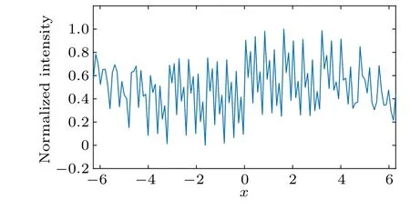
Fig.2.Results of adding Gaussian wavelets together(for a clearer view,the results are normalized to interval[0,1]).
In order to solve this issue, we propose the SCWT scheme. Basically, the SCWT is based on a DWT. The basic idea is to“fill the gaps”between the wavelets by introducing redundant wavelet sets into the measurement basis. The principle is simple, we additionally introduce several copies of the original wavelet set,but with different phase delays(see Fig.3).
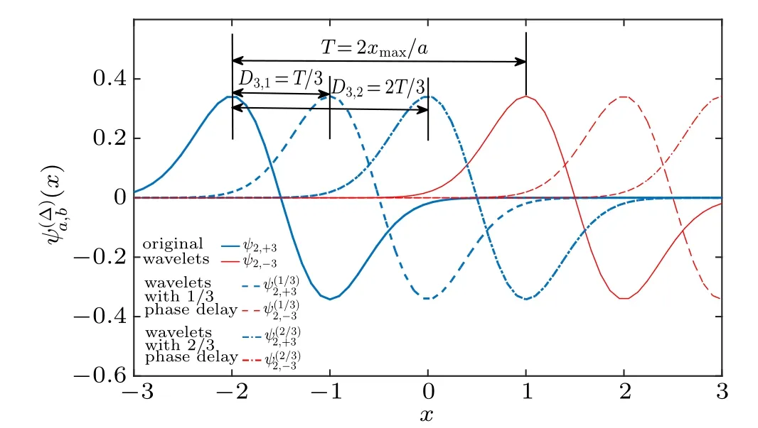
Fig. 3. Diagram of the basic idea of the SCWT, where (x) =ψ(ax-ab-Dn,k). In this case, Gaussian wavelet defined in interval[-3, +3] is used as the mother wavelet ψ(x). Wavelets under zoom scale 2 (a=2) are shown (blue bold and red thin line). The number of the wavelet set n is taken to be 3,so that two additional wavelet sets are introduced,with 1/3(dashed)and 2/3(dot-dashed)periods of phase delay,respectively. Notice that after the wavelet sets are introduced,the“gap”between wavelets ψ2,+3 and ψ2,-3 is filled.
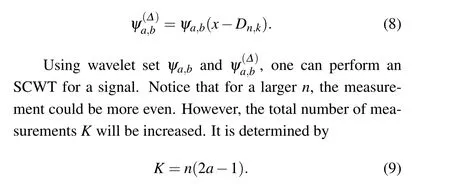
LetDn,kbe the delay of the wavelets which are additionally introduced. Obviously, it is related with scale coefficientaby

wherer/adenotes the effective length of the wavelets, andΔis the phase delay coefficient that determines the phase delay of the wavelets. In order to obtain a measurement basis set which can evenly measures the target object,letΔbek/n(wheren,kcan only be integers, andk <n). Thus, (n-1)copies of the original wavelet sets with different phase delays is obtained as follows:
Simulations are performed to judge the performance of the SCWT scheme. First, in order to check whether the wavelet set can give the signal of an even measurement, the sum of wavelets is calculated under differentn. The results are shown in Fig.4.
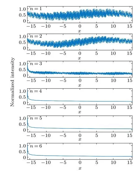
Fig. 4. Mean of wavelets in the SCWT wavelet set, coefficient r=5,under different n(normalized into interval[0,1]).
As shown in Fig. 4, one may get a better reconstruction whennis larger. By the way,boundary effect can be found on negative direction of axisx,it is due to the lack of wavelets on the left side. Then, we perform the SCWT for a square wave signal,and the results are shown in Fig.5.
Obviously, the quality of reconstruction is significantly improved under largern.
Based on the same reason,shortening the definition interval of the mother wavelet can also be effective to remove the grid-like distortions.
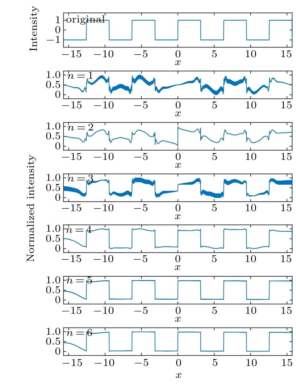
Fig. 5. The SCWT for a square wave signal, coefficient r=5, under different n.
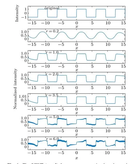
Fig. 6. The SCWT (n =3) for a square wave signal, under mother wavelets defined in different intervals[-xmax,+xmax]. Here r=2xmax is the length of the interval.
Figure 6 shows the SCWT for a square wave signal, using mother wavelets defined in different intervals whenn=3.It is found that by decreasing the interval length,the grid-like distortions can be significantly removed. However,because of the decrease of basis spatial frequency,this method will eventually decrease the spatial (or temporal) resolution of reconstructed signal. Applying appropriate combinations of coefficientnandr,the SCWT scheme is proved to be effective.
3. Single pixel imaging based on an SCWT
By a clear understanding of an SCWT, a single pixel imaging system based on the SCWT(SCWP-SPI scheme)can be established easily.
In an ordinary SPI system, a projector is needed to provide modulated light source to illuminate the target object.The transmitted light is collected by a bucket detector(a single pixel detector,like a photon-diode). The light source is modulated into illumination patterns, and projected on the target object sequently. At the same time, the corresponding transmission intensity is collected by the bucket detector, and the bucket signal is recorded by the computer. Finally,the image of the object can be reconstructed as

whereNis the number of measurements,R(i)is thei-th pattern,andB(i)denotes the corresponding bucket signal,

wheret(x,y)is the transmission function of target object. Notice that Eq.(10)can be easily related with Eq.(5). If we assume that all of the transmitted light is collected by the bucket detector, the bucket signal could represent the transformation coefficients of basisR(i)(x,y). The whole SPI system can be considered as a linear transformation system in an optical way.Thus,by reshaping the 1D wavelets into 2D matrices and using them to generate illumination patterns,the SCWT-SPI system can be set up.
According to our theory, for the SCWT scheme, coefficientrandncan considerably influence the imaging quality and efficiency. By reducingr, smallernis needed to remove the distortions, which may significantly decrease the number of measurements. Notice that reducingrwill cause the decrease of spatial resolution. In practical situations,magnitude of coefficientrandnshould be considered to reach some kind of balance.Based on the simulation results shown in Section 2,for a Gaussian wavelet based SCWT-SPI, taker ≈3.5 andn=3 orn=4, one should obtain an enough spatial resolution and a moderate number of measurement,and with almost no distortions on the reconstructed image.
In this paper,we carry out experiments to verify our proposed SCWT-SPI (semi-continuous wavelet transform based single pixel imaging) scheme. Beyond the verification of the effectiveness of this scheme, we also discuss the potential issues in practical applications.
The schematic diagram of the experimental system is shown in Fig. 7: a digital projector is used to modulate the illumination patterns, the patterns are sequently projected on a transmission target (see Fig. 8(a)). At the same time, the photon-diode receives the transmitted light,and the photoelectric signal is recorded by the computer.
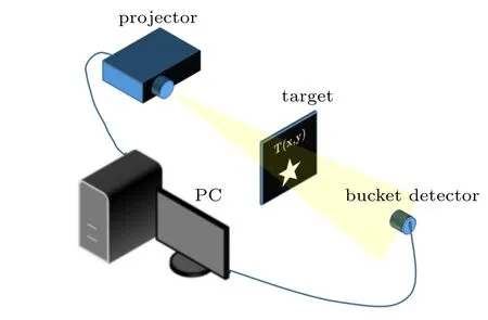
Fig.7. The schematic diagram of experiment.
The first issue is that one can not create an illumination pattern with negative values, i.e., negative intensity does not exist. However, there are negative values in the wavelets. The similar issue also exists in other SPI systems(e.g., Hadamard-SPI), one of the ways to solve this issue is reported in Ref. [32]: for a patternRwith negative values,separateRinto 2 parts,R=R-+R+. HereR- only consists the elements which are negative, while the rest elements ofRare inR+. In projection progress, project patternR+and(-R-), the corresponding bucket signalsB+andB- are obtained, then the measurement stepRBcan be replaced with(R+-R-)(B+-B-)with no more“negative illuminations”.
The second issue is the quantizing error of the digital projector,which is easy to be understood. A digital projector has a limited ability of grayscale representation. Taking an 8-bit grayscale projector as example, all the analog signal will be converted into an 8-bit deep digital signal,in which only 256(at most)levels of grayscale can be expressed in the projected image. How to effectively use the limited grayscale levels is worthy to be discussed and solved. For wavelets, the normalization constants can be separated from illumination patterns since they are only related to scale coefficienta. Thus,the illumination patterns can be generated by non-normalized wavelets:

For reconstruction, the normalization constants should be recovered, it can be included in the basis we use to reconstruct the image:

Thus,the current reconstruction reads
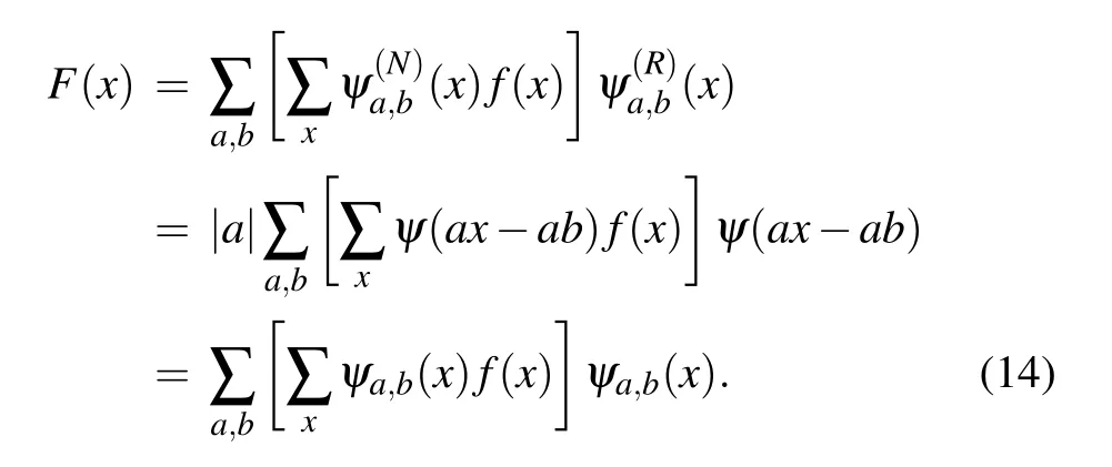
It is equivalent to the original reconstruction progress. However,the utilization rate of the projector’s grayscale representing ability is significantly improved.
In our experiment, the issues mentioned above are considered. The spatial resolution of the reconstruction is taken to be 64×64, a 12 levels 1D-Gaussian wavelet set is applied to produce the illumination patterns. We set the SCWT coefficientsn=3, in which 12285 measurements are taken. The reconstruction results are shown in Fig.8.

Fig.8. Experimental results of the Gaussian-SCWT-SPI:(a)the target object, i.e., a transmitting star, with size ~7 mm×7 mm; (b)reconstructed image when r=3.5;(c)reconstructed image when r=4.5.
We use the signal-to-noise ratio (SNR) and root-meansquare errors (RMSEs) to judge the quality of the reconstructed image. They are defined as


whereNis the number of pixels,Img(x,y)is the reconstructed image, andO(x,y) is the discrete ideal image of the object,both of them are normalized to interval [0,1]. For the SNR,the corresponding imaging quality is better when its magnitude is greater. On the contrary, the quality is worse with a high magnitude of RMSE since it judges the deviation between the reconstructed image and the target object. For the results of SNR and RMSE in Fig. 8, we have (b) SNR = 2.5661,RMSE=0.1728;(c)SNR=1.4377,RMSE=0.2571,which suggest that Fig.8(b)is better since there are grid-like distortions in Fig.8(c). According to the results shown in Fig.8,the SCWT-SPI scheme is proved to be realizable in practice.
4. Compressed reconstruction of Gaussian wavelet based SCWT-SPI
In this section, the compressing ability of SCWT-SPI is discussed. The reconstructed image can be considered as the linear superposition of the basis (i.e., the illumination patterns), thus the shape of the basis may significantly influence the compress reconstruction ability. Thus, the smooth wavelets can be effective for the transmission and reconstruction of a smooth signal, which leads to a considerable compress ratio of the information of the object.Most of the smooth wavelets are non-orthogonal, in which the SCWT scheme is required. In this work, we are going to judge the compress ability of Gaussian wavelet based SCWT-SPI.
The basic idea is simple, the SCWT-SPI scheme can be considered as a linear transformation system for a signal(in an optical way). The transformation coefficients(i.e. the bucket signal)represent the coherence between the corresponding basis (i.e., the illumination patterns) and the signal itself. Obviously, the coefficients with larger absolute value has more information about the target,which are more important in reconstruction progress since they do more contributions reconstructing the signal. Based on this idea, by removing some coefficients with smaller absolute values, one can get a faster reconstruction and a higher compression ratio for an image signal. In this section, we exhibit the compressive ability of Gaussian wavelet based SCWT-SPI via experiments. Then, a comparison between the proposed SCWT-SPI scheme and two ordinary SPI schemes using Hadamard and Sinusoidal patterns are made,and we introduce the efficiency and effectiveness of the SCWT-SPI scheme.
4.1. Compressed SCWT-SPI
In this part, we apply an SCWT basis set built by Gaussian wavelet to generate the illumination patterns. A threshold is introduced to select the bucket signals. If the absolute value of the current bucket signal is smaller than the threshold, the corresponding measurement step will be removed. Only the measurements with greater contributions will be survived. LetCrepresents the compress ratio of the signal,which is defined as

whereNis the length of the image signal,andNeis the number of the survived measurements.
We initially verified the compressed reconstruction for a image of an 2D-object. The experiment results are shown in Fig.9.
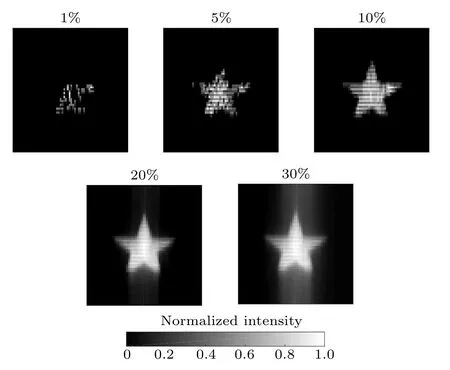
Fig.9. Compressed imaging for the target object shown in Fig.8(a). The labels denote the compression ratio C.The SCWT coefficients n=3,r=3.5 are selected. The resolution of the reconstructed images are 64×64 pixels, and the numbers of reconstruction are 41,205,410,819,and 1229,respectively.
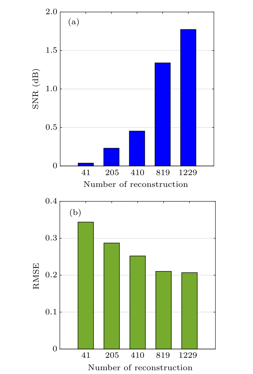
Fig.10. SNR and RMSE of the reconstructed image shown in Fig.9.
The corresponding SNR and RMSE of the reconstructed images are also given in Fig.10.
According to the results shown in Figs. 9 and 10, an acceptable quality of the reconstructed image can be obtained with only~20% of measurements, the SNR and RMSE are well close to the non-compressed reconstruction results shown in Fig. 8(b), which means that the SCWT-SPI can realize the compressed imaging for a 2D-object in practice.
4.2. Comparison of the compressive ability between the SCWT and other existing SPI schemes
In the single pixel imaging system, Hadamard patterns and sinusoidal patterns are two ordinary types of illumination patterns,the corresponding imaging scheme is usually referred as the Hadamard transform imaging (HTI)[23]and the sinusoidal ghost imaging (SGI).[25,26]In order to exhibit the efficiency and effectiveness of our proposed SCWT scheme, we will compare the ability of compressive imaging of our proposed SCWT scheme with these two schemes via simulations.
In our simulations, a 64×64 pixel image is used as the target object(Fig.11).

Fig. 11. Target object of the simulation: transmissive letters “CUST”and several transmissive dots around the letters,64×64 pixel.
For the SCWT scheme,we use Gaussian wavelets to generate the illumination patterns, and set SCWT coefficientsr=3.5 andn=3. For all the three schemes, the thresholds are set to reduce the total number of reconstructions. For the results with different numbers of reconstruction, the reconstructed images and the corresponding SNR/RMSE are shown in Figs.12 and 13,respectively.

Fig.12. Comparison of the compressive imaging with the three schemes(the reconstructed image of target object shown in Fig.11). The labels in every column are the numbers of reconstruction.
Obviously, among these three schemes, under the same number of measurements, our proposed SCWT scheme has a higher SNR and lower RMSE,which suggests that the reconstruction quality is better than the other two schemes. On the other hand,as the results shown in Fig.12,for reconstruction number of 1024 (the 3rd column,C=25%), the dots in the top left corner of the target object is missing in the images reconstructed by the HTI and SGI schemes, while they can be clearly seen in the image reconstructed by SCWT scheme.This feature is caused by the localization and de-correlation of wavelet analysis. The energy of the wavelet bases with high scale level is localized in a small area.Thus,in spatial domain,the wavelets only interact with a small part of the signal and extract the corresponding information. Every portion of localized information of the object can be captured precisely by corresponding wavelets without introducing information from other parts. On the other hand,HTI and SGI are corresponded with Hadamard transform and discrete Fourier transform, respectively.Compared with wavelet transform,they are“global transforms”, in which the transform bases are always defined in the whole space. In this case,those localized non-stationary and sudden-change parts of the signal will be regarded as unnecessary information. Finally, in low sample-rate situation, such information will be missing. From this viewpoint,our proposed scheme has a better performance in compressive imaging than the other two existing imaging schemes.
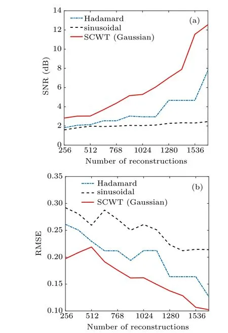
Fig.13. Comparison of SNR and RMSE for the three schemes, under different numbers of reconstruction.
5. Summary and discussions
In this paper,we have proposed and established the a 1DSCWT protocol. It gives considerations of both the concise of DWT and the advantage of CWT:representing smooth signals, such a protocol may have potential to compress a signal effectively. By taking 1D-Gaussian wavelet as an example, the method for introducing an SCWT into an SPI system is given, two important coefficients of the SCWT (i.e.nandr) are introduced and discussed to give a guide to apply SCWT protocol appropriately.Furthermore,we discuss the issues that may occur in actual practice,the corresponding solutions are given,and the results are verified by simulations and experiments, which meet the prediction of our theory. Also,our initial results of simulations and experiments show that SCWT-SPI could have the ability to realize compressed imaging (with≈20% sample rate) for an object. Compared with Hadamard and sinusoidal based single pixel imaging,the proposed SCWT scheme has a better reconstruction performance under low sample rate, especially for the extraction of nonstationary and sudden-change features in target object,which is quite useful in practical applications.
On the other hand, the proposed protocol opens a new area of illumination pattern modulation for the SPI system.The SCWT-SPI protocol can be considered as a basic idea for a series type of SPI systems. Theoretically, it allows to use any type of wavelet to generate illumination patterns, as long as the wavelets used are available for the CWT.Further works can be developed from two directions: (i) Consider the 2Dform of an SCWT, set up the 2D-SCWT-SPI scheme. In this paper,we have proposed the 1D-form of an SCWT.Although we realize 2D-imaging for an object, our experiment is only in verification purpose (to judge wether the SCWT-SPI system is effective in actual practices). The illumination pattern is actually generated by 1D wavelets, reshaped into 2D matrices. In fact, for 2D imaging, the feature of the target can be better extracted using 2D wavelet basis. The compressing ability can be further improved.(ii)Investigate other wavelets.Different wavelets may have advantages in reconstruction or extracting different type of features. The setup of an SCWT protocol made it possible to use various wavelets to realize SPI, especially those non-orthogonal wavelets which can not realize DWTs. Thus,it would be a large and interesting topic to explore.
- Chinese Physics B的其它文章
- Numerical simulations of partial elements excitation for hemispherical high-intensity focused ultrasound phased transducer*
- Magnetic-resonance image segmentation based on improved variable weight multi-resolution Markov random field in undecimated complex wavelet domain*
- Structure-based simulations complemented by conventional all-atom simulations to provide new insights into the folding dynamics of human telomeric G-quadruplex*
- Dual-wavelength ultraviolet photodetector based on vertical(Al,Ga)N nanowires and graphene*
- Phase-and spin-dependent manipulation of leakage of Majorana mode into double quantum dot*
- Deep-ultraviolet and visible dual-band photodetectors by integrating Chlorin e6 with Ga2O3

