Rapid directionally solidified microstructure characteristic and fracture behaviour of laser melting deposited Nb-Si-Ti alloy
Wei Liu,Xinyu Ren,Neng Li,Chao Gao,Huaping Xiong
3D Printing Research and Engineering Technology Center,Beijing Institute of Aeronautical Materials,Beijing,100095,China
Keywords:Nb-Si based Alloy Laser melting deposition Directional solidification Microstructure characteristic Fracture behaviour
ABSTRACT Aiming at achieving fine and directionally-solidified microstructure of Nb-Si based alloy,Nb,Si and Ti powder particles were utilized as the raw materials,and laser melting deposition(LMD)experiments were conducted with 1500 W and 2000 W laser power,respectively.The microstructure characteristic,micro-hardness,and indentation fracture toughness were examined by scanning electron microscope(SEM),X-ray energy dispersive spectrometer(XEDS) and X-ray diffraction (XRD).The results showed that the two kinds of as-deposited Nb-17Si-23Ti alloy samples were mainly composed of NbSS,(Nb,Ti)3Si and Ti-rich NbSS,and the microstructure presents rapid directionally-solidified characteristic,in which the <100>crystallographic direction of NbSS and <110>crystallographic direction of (Nb,Ti)3Si tend to be parallel to the LMD building direction.With the laser power increasing from 1500 W to 2000 W,the microstructure became more oriented and homogeneous.For the sample at 2000 W,the dendrite spacing was only about 1-2 μm,and NbSS and (Nb,Ti)3Si couples grow alternately and they are parallel to the building direction strictly.In the meantime the micro-hardness and indentation fracture toughness reached 1075 HV and 20.3 MPa·m1/2,respectively,indicating significant improvement by the directional growth of fine NbSS and (Nb,Ti)3Si phases,and the dimple fracture mode of the NbSS dendrites.
1.Introduction
Nb-Si based refractory alloys have the greatest potential to replace nickel-based superalloys and have become new generation ultra-high temperature structural materials which can offer the service temperature of 1200-1400°C due to their high melting point,high stiffness,low density,and attractive specific mechanical properties at elevated temperatures.Therefore the Nb-Si based alloys have received considerable interests in material research field [1-3].In general,they are mainly composed of the metallic NbSS(Nb solid solutions) which offers room-temperature ductility and the reinforcing silicide which supplies mechanical strength and creep resistance at high temperatures.To balance the properties of their ductility and the strength at room temperature and elevated temperatures is still a great challenge[1,4].However,it has been recognized that sound comprehensive properties can be achieved from the Nb-Si based alloys possessing directionally solidified microstructure [5].As an example,for the Nb-16Si-24Ti-8H-2Al-2Cr alloy prepared by directional solidification(DS),its fracture toughness at room temperature is up to 23.0 MPa·m1/2,while 400 MPa compressive strength was still maintained at 1200°C [6].
Up to date,several directional solidification techniques including Czochralski’s cold crucible method[7],electron beam float zone melting technology [8],optical floating zone melting technology (OFZ) [9],integrally directional solidification (IDS) [10] and electromagnetic cold crucible directional solidification(ECCDS)[5,11],have been used in the preparation of Nb-Si based alloys.However,these Nb-Si based alloys fabricated by these traditional DS techniques usually possess coarse microstructure and exhibit element segregation due to the limited temperature gradient and low solidification rate during the process.So far,it is still extremely difficult to fabricate Nb-Si based alloy components with complex shape such as the aero-engine hollow blades by traditional DS techniques.
Compared with the directional solidification process schemes of Nb-Si based alloys described previously,laser melting deposition(LMD),as one of additive manufacturing processes,is characterized by rapid melting and solidification process.Therefore by LMD method it can be easier to achieve fine microstructure and to depress composition segregation within the fabricated alloys,and thus to improve their comprehensive properties[12,13].Several examples can be found for achieving fine microstructure directional growth by LMD through optimizing processing parameters [14-17].For instance,directional rapidly solidified nickel-base superalloy Rene’41 with extremely fine cellular dendritic structures was successfully obtained by LMD,with an average primary dendrite arm spacing of approximately 35 μm[15].More important,by the LMD,near net shape complex components with high melting point can be produced without crucible or mould[18],and this is undoubtedly beneficial to preventing contamination into the fabricated Nb-Si based alloys.
Up to now,the attempts have been made for fabricating Nb-Si based alloys by additive manufacturing.For example,Nb-22Si-26Ti-6Cr-3Hf-2Al alloy was deposited by laser directly forming from pre-alloyed powders,and the results showed that the higher powder feeding rate and lower scanning rate were necessary for stable forming process[19].A remarkably refined microstructure with the NbSSphase size of 1-3 μm was reported in Nb-17Si-23Ti alloys by in-situ reaction laser melting deposition [20].Additionally,the as-built Nb-18Si-24Ti-2Cr-2Al-2Hf alloy block by selective laser melting(SLM)consisted of Nbss,α-Nb5Si3,β-Nb5Si3and Nb3Si,in which the sphere-shaped NbSSphases showed very small size of only 300 nm diameter [21].However,so far,the directionally solidified microstructure of Nb-Si based alloys by additive manufacturing has not been reported.
In the present study,not only refined but also directionally solidified microstructure was realized in Nb-17Si-23Ti ternary alloy by LMD,with raw materials of Nb,Si and Ti powder particles.The influence of laser power on the microstructure characteristic of this alloy was investigated.Furthermore,micro-hardness and indentation fracture toughness were also examined aiming at better understanding of the refined and directionally solidified microstructure characteristic,as well as the corresponding fracture behaviour.
2.Experimental
The Nb(99.9 wt%purity),Si(99.6 wt%)and Ti(99.9 wt%)powder particles were utilized as the raw materials,and to assure the feeding rate and to acquire the Nb-Si-Ti alloys with a target composition,the powder particles with near equiaxed morphology and approximately 80 μm in size were chosen for LMD experiment,as shown in Fig.1.
The deposition substrate employed was pure Nb plate with the size of 100 mm×100 mm×10 mm.LMD experiments were conducted using a 6 kW optical fibre laser processing system with six-axis numerical control working table and two independent powder feeding units.Argon was used as the shielding gas for protection of the molten pool.Dual powder feeding method as schematically illustrated in Fig.2 (a),was used to deposit the Nb-Si-Ti alloy samples.The laser beam and coaxial powder feeding nozzle move as an integral unit so that the powder particles from the two feeding units are delivered coaxially into the laser molten pool.
As shown in Fig.2(a),pure Si powder particles were delivered through one feeding unit and another feeding unit for Nb+Ti powder mixture with the composition of Nb-17 wt%Ti.By adjusting the feeding rate of the two independent feeding units,the 0.5 g/min of powder mass flow rate for the Si powder and 7 g/min for the Nb+Ti powder mixture,respectively,the Nb-Si-Ti alloys with the target composition of Nb-17Si-23Ti(at.%)might be achieved by LMD.
Based on a series of experiments the LMD processing parameters were chosen as listed in Table 1.An optical fibre laser of beam diameter 0.8 mm was used with 13 mm defocus distance,and single-pass scanning strategy was adopted in these LMD experiments.Laser scanning speed was fixed at 600 mm/min but two laser power values of 1500 W and 2000 W were used for comparison.Only 20 layers were deposited in the process,in order to prevent hot cracks caused by the thermal stress with the number of deposition layer increasing.The as-built samples were with the dimension of about 50 mm(length)×8 mm(height)×3.5 mm(width).Two kinds of Nb-Si-Ti samples were prepared,as shown in Table 1.
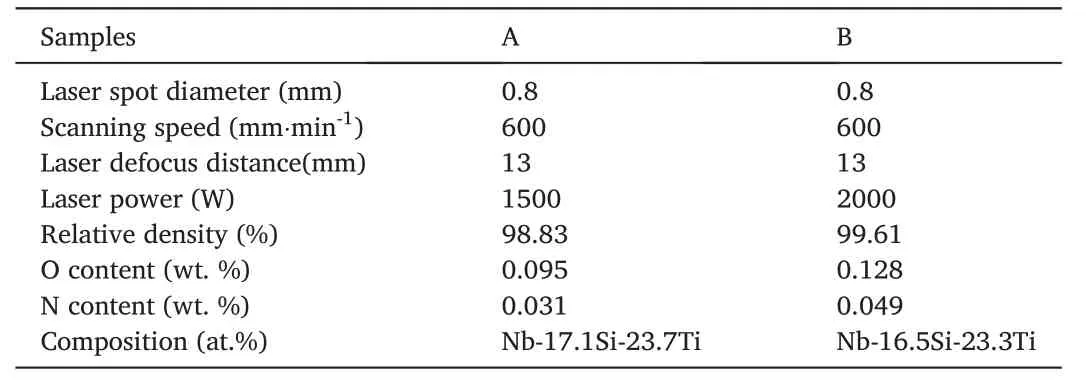
Table 1 LMD processing parameters,relative density and chemical composition of the deposited samples.
The as-deposited alloy samples were weighed in air and distilled water and,based on Archimedes principle the relative density of the samples was determined.TCH600 (LECO) O,N and H analyzer was used to measure the contents of oxygen and nitrogen in the samples.An X-ray diffraction analysis (XRD) was performed on the polished longitudinal sections (parallel to the building direction Z,Fig.1) of the as-deposited samples to identify the constituent phases,using filtered Cu Kα radiation,40 kV and 300 mA (RIGAKU RINT 2500).Secondary electron images(SEIs)of the powder morphologies,back-scattered electron images(BSEIs) of the specimen microstructure,cracks propagation paths at the tips of hardness indentation,and surface morphologies of the bendingfractured specimens were examined using a scanning electron microscope (FEI Quanta 200F).Chemical compositions of the constituent phases were analyzed using an X-ray energy dispersive spectrometer(XEDS).
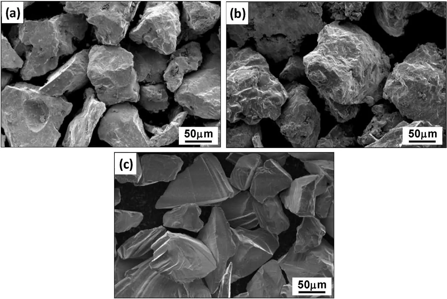
Fig.1.Morphologies of Nb (a),Ti (b) and Si (c) powder particles for the LMD experiment.
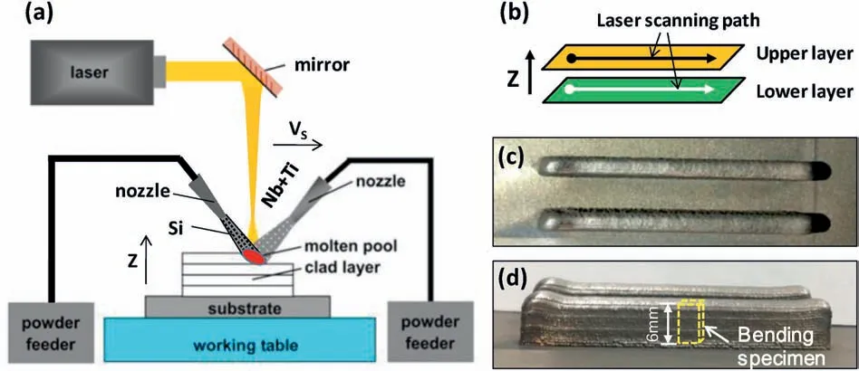
Fig.2.Schematics of LMD with dual powder feeding (a),single-pass scanning strategy (b),the top view (c) and side view (d) photographs of deposited samples.
Vickers hardness tests were measured using a digital micro-hardness tester(HXZ-1000)under a load of 1 kg for 15 s.The average Hv value was calculated from at least 5 measurements on each sample.The specimens with 6 mm in length,3 mm in width and 1 mm in thickness,as shown in Fig.2 (d),were specially machined from the as-deposited samples for bending destruction to build their fracture surfaces for observation.Additionally,the two kinds of deposited alloy samples were subjected to indentation test with a load of 2 kg.The lengths of the cracks at the edge of the indents were measured using SEM photos and the longest main cracks were selected to determine the lengths of the cracks.Then the indentation fracture toughness of the alloys was calculated according to the following equation[22].

Here‘E,H,P,I’refer to Young’s modulus,the hardness value,the test load and the crack length from the tips of hardness indentation,respectively.
3.Results and discussion
3.1.Microstructure characteristic
With the given processing parameters in Table 1,the samples A and B exhibited the chemical compositions of Nb-17.1Si-23.7Ti and Nb-16.5Si-23.3Ti,respectively,showing only slight deviation from the target composition Nb-17Si-23Ti.The fully dense samples with a relative density (ρ) higher than 98.8%were successfully fabricated by the LMD,with low-level content of Oxygen(≦0.128 wt%)and Nitrogen(≦0.049 wt %).
Fig.3 shows the XRD of the two Nb-17Si-23Ti alloy samples,in which the diffraction peaks of bcc Nb (JCPDS34-0370) and tetragonal Nb3Si silicide (JCPDS22-0763) were identified whereas the XRD peaks associated with Si or any other compounds were absent.Evidently,the two as-deposited Nb-17Si-23Ti alloy samples mainly consist of the same two phases,NbSSand Nb3Si.Based on the Nb-Si-Ti ternary phase diagram,Nb3Si is a metastable phase at room temperature [23].However,the metastable Nb3Si was confirmed in most Nb-Si binary or Nb-Si-Ti ternary alloys fabricated by cast methods owing to the incomplete or sluggish eutectoid reaction [24,25].Due to the rapid solidification characteristic of LMD process and the stabilizing effect of element Ti for Nb3Si at lower temperature[26],the eutectoid decomposition reaction of Nb3Si→Nb+Nb5Si3,would be suppressed entirely.Thus only one kind of Nb-based silicide was present in the Nb-17Si-23Ti alloy samples prepared by the LMD.
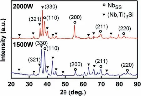
Fig.3.XRD patterns for the longitudinal section of Nb-17Si-23Ti alloys by LMD.
It is worth noting that the relative intensity of the peaks in the XRD profiles is different from the data of JCPDS.According to JCPDS34-0370 of Nb and JCPDS22-0763 of Nb3Si,the strongest peaks of Nb and Nb3Si are (110) and (321) crystal planes,respectively.However,the XRD patterns of the two as-deposited alloys (Fig.3) show that the strongest peak associated with the Nb3Si has changed from (321) to (330) plane,and the(200)plane has become the strongest peak for NbSSof the alloy fabricated by 2000 W laser power.This should be due to the preferred crystal orientation of the as-deposited Nb-17Si-23Ti alloy samples.During the LMD process,the grains with favourable crystallographic orientation grew preferentially and in the meantime the grains in the unfavourable crystallographic direction were eliminated.As for the NbSSand Nb3Si,the <100>and <110>crystallographic orientations are the preferred growth direction,respectively,and thus the highest growth rate can be found in these directions.However,this is inconsistent with the previous study results:the NbSS(110)and Nb5Si3(310)are parallel to the growth direction in the DS Nb-22Ti-16Si-7Cr-3Al-3Ta-2Hf-0.1Ho fabricated by OFZ(optical floating zone melting)technique[27],and the preferred growth directions are Nbss <113>and Nb3Si <001>when the DS rate was higher than 150 mm/h [28].It appears that the preferred growth direction of Nb-Si based alloys is closely related to the specific processing condition.
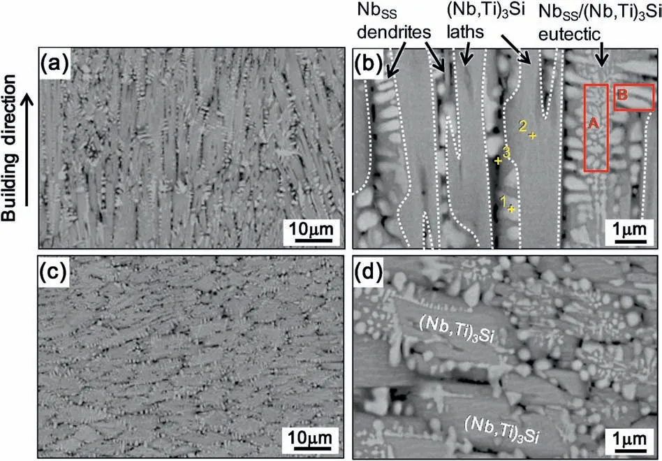
Fig.4.BSEIs of longitudinal sections (a,b) and transversal sections (c,d) for the as-deposited Nb-17Si-23Ti alloys with laser power of 1500 W.
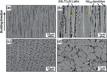
Fig.5.BSEIs of longitudinal sections (a,b) and transversal sections (c,d) for the as-deposited Nb-17Si-23Ti alloys with laser power of 2000 W.
The BSEIs of the longitudinal and transversal microstructure for asdeposited alloy samples of 1500 W and 2000 W are shown in Fig.4 and Fig.5,where three phases (bright,grey and dark) are observable.XEDS analysis results are given in Table 2.With both the XRD and XEDS results (Fig.3 and Table 2),the bright and grey phases (the former“1”and“4”,and the latter“2”and“5”)in Figs.4 and 5 can be identified as NbSSand(Nb,Ti)3Si,respectively.Besides,there are some black phases(points“3”and“6”in Figs.4 and 5) called as Ti-rich NbSSphases,indicating the micro-composition-segregation in the NbSSdendrites.

Table 2 XEDS analysis results for the the points marked in Figs.4 and 5.
From the longitudinal sections of the as-deposited alloy with the laser power of 1500 W(Fig.4(a and b))and 2000 W(Fig.5(a and b)),it can be seen that the constituent phases of NbSSand (Nb,Ti)3Si tend to be parallel to the building direction,and they exhibit alternate distribution with each other.The two LMDed Nb-17Si-23Ti alloy samples present typical directionally solidified microstructure characteristic,and no transverse boundary in the microstructure is observable,which may be beneficial to the mechanical properties of alloys in the longitudinal direction[29].During the LMD process,due to the cooling effect caused by the substrate,most of the heat transport along the negative Z-direction(Fig.2 (b)) and so the temperature gradient along the positive Z-direction (Fig.2 (b)) is established.With the highest temperature gradient in the Z-direction,the growth direction of NbSSand(Nb,Ti)3Si phases is approximately parallel to Z-direction[30].In addition,the(Nb,Ti)3Si phase is the primarily deposited phase and the alloys show a hypereutectic microstructure,which due to the Ti alloying can reduce the volume fraction of NbSSphase in Nb-Si-Ti alloys and this makes the alloy composition to become close to hypereutectic and it is easy to form coarse continuous Nb3Si phase[31,32].
Fig.4 shows the microstructure of the alloy prepared with 1500 W laser power.The primary(Nb,Ti)3Si laths are very long but only 3 μm or less in width,and the NbSSphases (including NbSSand so-called Ti-rich NbSS) growing coupled with (Nb,Ti)3Si also present dendritic morphology (Fig.4 (a),(b)).Besides,the NbSS/(Nb,Ti)3Si eutectic colonies are also found in this alloy,characterized by aligning along the building direction in the longitudinal section (Fig.4 (b)).In the meantime,in the centre of the eutectic cells,quasi-spherical or rod-like NbSSphases with nanoscale size(zone“A”in Fig.4(b))distribute on the(Nb,Ti)3Si matrix,but in the exterior margin of the eutectic cells,Nbss phases become coarser and some cellular or dendrite Nbss phases with the size of 300 nm-1.2 μm are formed(zone“B”in Fig.4(b)).
Compared with Figs.4 and 5,it is clear that with the increase of laser power from 1500 W to 2000 W the microstructure of the Nb-17Si-23Ti alloy becomes more oriented and homogeneous.NbSSand (Nb,Ti)3Si couples grow with periodic alternation,and they are strictly parallel to the building direction.This should be related with more stable heat flow and steeper temperature gradient during the LMD process with 2000 W laser power.In the longitudinal section the (Nb,Ti)3Si laths with long and straight boundaries are further refined to about 1-2 μm in width.It should be noted that the NbSSdendrites distribute with continuous network-like morphology on the (Nb,Ti)3Si matrix(Fig.5(c and d)),while the NbSS/(Nb,Ti)3Si eutectic microstructures observed in Fig.4 almost disappears.
For the microstructure of Nb-Si based alloys prepared by traditional DS technique,it was reported that the dendrite spacing is about 10-100 μm [33].In this study the dendrite spacing in the Nb-17Si-23Ti alloys prepared by LMD is remarkably decreased to the level of 1-2 μm,indicating the refining effectby1-2ordersofmagnitude.This can be attributed to not only the rapid cooling rate induced by the laser beam during the LMD process,but also the fact that the powder particles of Nb,Si and Ti elements were used as the starting materials for the LMD experiment.That is,the microstructure of the Nb-Si-Ti alloy could also be refined by the laser in-situ reaction of powder mixture[20,34-37].
3.2.Mechanical properties
The results of micro-hardness (Hv) and indentation fracture toughness (KQ) are presented in Table 3,in which the standard deviations of the data are also listed as a reference.The average Hv value of the sample prepared at 2000 W laser power is higher than that of the sample at 1500 W (1075 HV vs 964 HV).The main reason for the increase in Hv value with the laser power increasing should be caused by the more oriented and homogeneous microstructure (Figs.4 and 5).Besides,the concentration of elements Si and Ti in NbSSof the alloy at 1500 W is 3.81 at.%and 22.27 at.%,respectively,but that has been increased up to 4.67 at.%and 28.06 at.% in NbSSof the alloy at 2000 W (Table 2),respectively,indicating more evident solid-solution strengthening effect in NbSSwith the increase of laser power.

Table 3 Vickers hardness and indentation fracture toughness of LMDed Nb-17Si-23Ti alloys.
Due to the distinct orientation of directional solidification microstructure,the properties would present strong anisotropy.The roomtemperature fracture toughness of the alloys is significantly different in the direction of PD (parallel to the growth direction) and VD (perpendicular to the growth direction),as shown in Table 3.The fracture toughness of the alloy prepared at 2000 W laser is 20.3 MPa·m1/2in the VD direction,but only 5.8 MPa·m1/2in PD direction.
Table 3 also showed that the LMD processing parameter had an influence on the average indentation fracture toughness(KQ),even though the two kinds of samples presented almost the same composition of Nb-17Si-23Ti,that is,the value of KQwas increased from 18.7MPa·m1/2to 20.8 MPa·m1/2with the processing laser power increasing from 1500 W to 2000 W.
The fracture toughness and constituent phase of Nb-Si-Ti ternary alloys prepared by arc-cast,hot-pressing and directional solidification are listed in Table 4.It can be seen that the fracture toughness of as cast Nb-16Si alloy is only 5.6 MPa·m1/2.The values of fracture toughness were improved with Ti alloying,which indicates that Ti has a significant toughening effect on Nb-Si alloys.The fracture toughness of Nb-17.5Si-10Ti alloy prepared by OFZ directional solidification with constituent phases of NbSS+Nb3Si reached 15.4 MPa·m1/2.After heat treatment,the Nb3Si phases were completely transformed into Nb +Nb5Si3phase.The content of ductile NbSSphase in the alloy increased,and the fracture toughness increased to 18.7 MPa·m1/2.In this study,the extremely fine directionally-solidified microstructure of Nb-17Si-23Ti alloy was obtained by LMD at 2000 W,and the fracture toughness is improved significantly to 20.8 MPa·m1/2.
3.3.Fracture behaviour
The crack paths at the corners of indentation on LMDed Nb-17Si-23Ti samples with 1500 W and 2000 W are presented in Fig.6(a,c) and Fig.6 (b,d),respectively.The NbSSdendrites,(Nb,Ti)3Si intermetallic compounds,and NbSS/(Nb,Ti)3Si eutectic phases show different behaviour during penetration of the hardness indenter.For the(Nb,Ti)3Si laths,the micro-cracks generally propagate continuously throughout it,as marked by the long cracks in Fig.6(a) and (c).According to previous study [25],the fracture toughness of (Nb,Ti)3Si is less than 3.0 MPa·m1/2so that the (Nb,Ti)3Si compounds cannot effectively stop the crack propagation,and this explains the reason why the as-deposited samples exhibit such low values of fracture toughness in the PD direction(6.4 MPa·m1/2and 5.8 MPa·m1/2in Table 3).
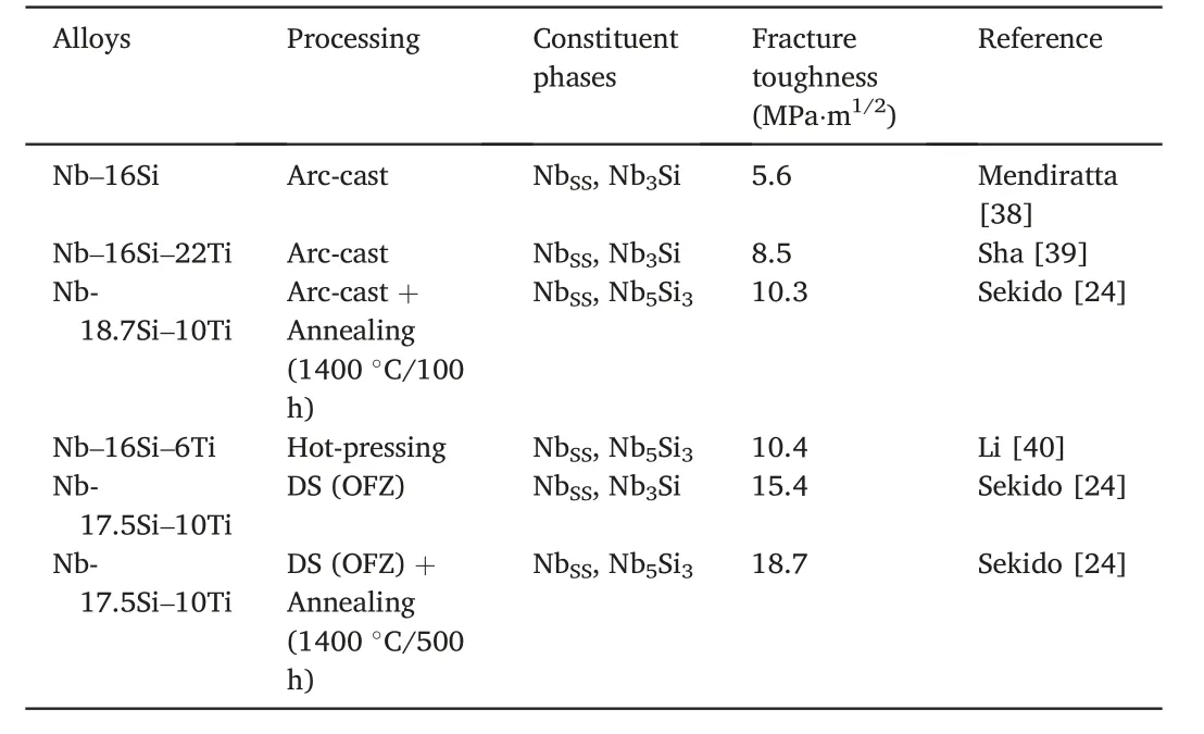
Table 4 Fracture toughness of Nb-Si-Ti ternary alloys fabricated by different processes.
In general,the micro-cracks will propagate in the NbSS/(Nb,Ti)3Si eutectic through bridging(arrow B in Fig.6(b))and deflection(arrows D in Fig.6(b)).It has been confirmed that the too small NbSSphases can notinhibit the cracks effectively [5].However,when the cracks meet the NbSSdendrite,in most cases they would be arrested (arrows A in Fig.6(d)).It can be concluded that different phases show different crack-propagation resistance:NbSS>NbSS/(Nb,Ti)3Si eutectic >(Nb,Ti)3Si.In particular,the NbSSphase plays an important role in obstructing the crack propagation in the as-deposited Nb-Si-Ti alloys through its ductility and toughening mechanism.The behaviour of the crack interaction with the NbSSdendrite is believed to have consumed more strain energy concentrated at the crack tip,and this will improve the bulk toughness of the Nb-Si-Ti alloys.As shown in Fig.5,for the microstructure of the DS alloy with the alternate distribution of NbSSdendrites and(Nb,Ti)3Si,when the crack propagation path is perpendicular to the continuously oriented NbSSdendrites,the crack must be fully cut,instead of going along the(Nb,Ti)3Si phases[4,41,42].
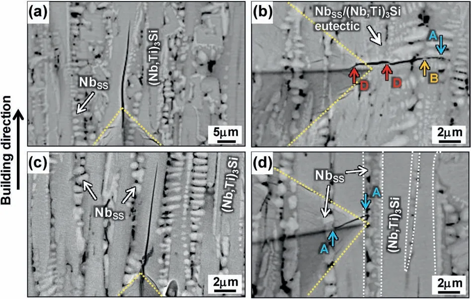
Fig.6.BSEIs of the cracks at the tips of hardness indentation on Nb-17Si-23Ti alloy fabricated by LMD at 1500 W (a,b) and 2000 W (c,d).
Fig.7 shows the bending fracture surfaces of the transversal section of the two as-deposited alloy samples.As for the (Nb,Ti)3Si phases,its smooth surface revealed brittle fracture characteristic,which is consistent with that of Nb-Si based alloys reported previously [7].However,the NbSSphases show completely different fracture feature.That is,for the fracture surfaces of the alloy sample at 1500 W,the NbSSphases seem to be pulled out from the (Nb,Ti)3Si matrix (arrows in Fig.7 (a)).As described previously,some NbSS/(Nb,Ti)3Si eutectic phases (Fig.4),characterized by the distribution of quasi-spherical or rod-like and fine NbSSphases on the(Nb,Ti)3Si matrix,are found in the sample at 1500W.In this case,the cracks tend to propagate along the NbSSand(Nb,Ti)3Si interface and bowl the NbSSphases so that the pull-out features of NbSSare observable.Concerning the microstructure of NbSSdendrite in the Nb-17Si-23Ti alloy sample at 2000 W,the continuous network-like NbSSphases surround(Nb,Ti)3Si compounds (Fig.5).In this way the energy consumed by the cracks propagating around the NbSSphases is greater than that of cutting through the NbSSphases.Therefore,the fracture surfaces of ductile NbSSphases are visible (arrows in Fig.7 (c)).It is worth noting that the dimple fracture mode of NbSSphases is clearly observed in the sample prepared by LMD at 2000 W,greatly different from the cleavage fracture mode of the NbSSphases in the most Nb-Si based alloys fabricated by other traditional techniques[4,9,10].It is the transformation of fracture mode from cleavage to dimple that caused the increase of KQvalue for the alloy sample fabricated by LMD at 2000 W.
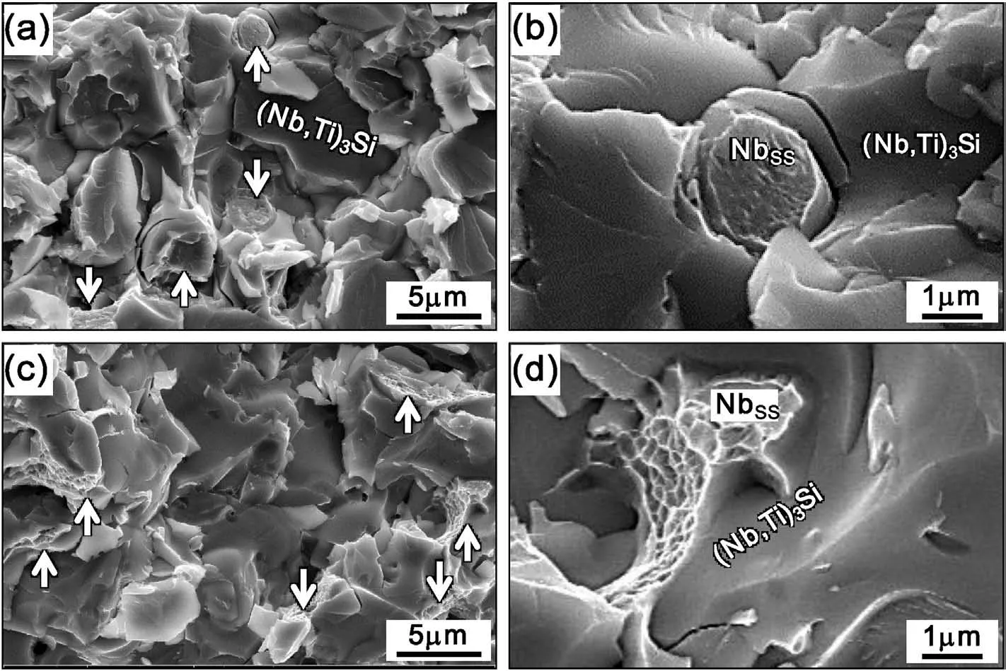
Fig.7.Fracture surfaces of the Nb-17Si-23Ti alloy samples fabricated by LMD at 1500 W (a,b) and 2000 W (c,d).
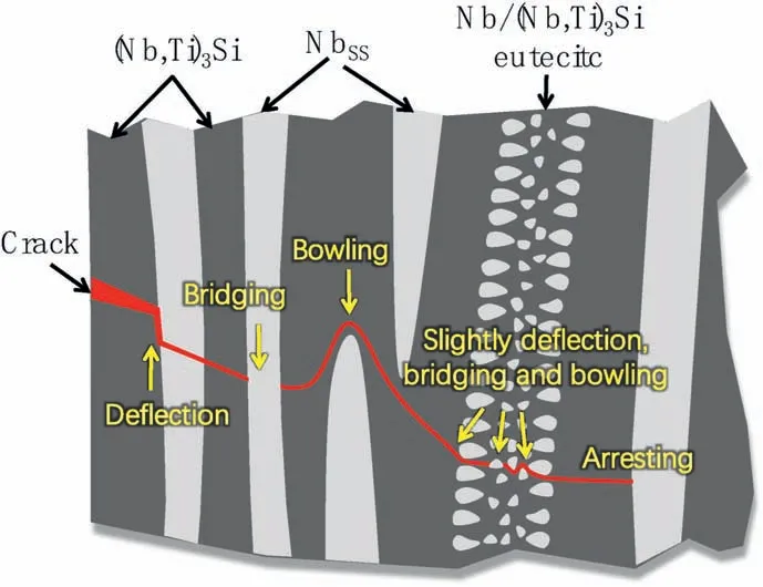
Fig.8.Schematic of crack propagation in different microstructures of LMDed Nb-17Si-23Ti alloy.
Fig.8 summarizes the interaction mode between the crack propagation and the different microstructures in the LMDed Nb-17Si-23Ti alloy.When the crack meets the(Nb,Ti)3Si laths,it continuously goes through the (Nb,Ti)3Si laths,and when meeting the interface of NbSSand (Nb,Ti)3Si,it may go along the interface and deflect.As the crack goes through the NbSS/(Nb,Ti)3Si eutectic,deflection,bridging or blowing mechanism may work but only slightly for the small size of NbSSin NbSS/(Nb,Ti)3Si eutectic.Concerning the crack perpendicular to NbSSdendrite,it will be eventually stopped by the ductile large-size Nb phase.In the fields of materials and processing technologies,further research work is still needed for deeper understanding and engineering application of Nb-Si based refractory alloys [4,6,19,20,43-45].
4.Conclusions
Dense Nb-17Si-23Ti alloy samples have been fabricated by in-situ reaction LMD technique using different laser power of 1500 W and 2000 W,with Nb-17 wt%Ti powder mixture and pure Si powder as the starting materials.
1) The two kinds of as-deposited Nb-17Si-23Ti alloy samples are mainly composed of NbSS,(Nb,Ti)3Si and a small amount of Ti-rich NbSS.The microstructure presents directionally solidified characteristic,in which the <100>crystallographic direction of NbSSand <110>crystallographic direction of(Nb,Ti)3Si tend to be parallel to the LMD building direction.
2) With the laser power increasing from 1500 W to 2000 W,the microstructure becomes more oriented and homogeneous.The NbSSand(Nb,Ti)3Si couples grow with periodic alternation,and they are parallel to the building direction strictly.For the laser power of 2000 W,the dendrite spacing of the as-deposited alloys is only about 1-2 μm,and the NbSSdendrites distribute with the continuous networklike morphology on the(Nb,Ti)3Si matrix.
3) For the LMDed samples,the cracks can propagate through the (Nb,Ti)3Si continuously,and propagate in the NbSS/(Nb,Ti)3Si eutectic through deflection,bridging and bowling mechanism,but in most cases they would be arrested by NbSSdendrites.The crack propagation resistance of different microstructure meets the following sequence:NbSS>NbSS/(Nb,Ti)3Si eutectic >(Nb,Ti)3Si.
4) The as-deposited sample with 2000 W laser power exhibits the microhardness of 1075 HV and indentation fracture toughness of 20.3 MPa·m1/2,and the toughening effect mainly results from the directional growth of NbSSand(Nb,Ti)3Si phases,and the dimple fracture mode of the NbSSphases.
Declaration of competing interest
The authors declare that they have no known competing financial interests or personal relationships that could have appeared to influence the work reported in this paper.
Acknowledgements
The authors are grateful to the support from the National Natural Sciences Foundation of P.R.China (Grant No.51605456 and No.51775525).
 Progress in Natural Science:Materials International2021年1期
- Progress in Natural Science:Materials International的其它文章
- Dynamic response characteristic of 7N01/7A01/7050 aluminium multilayer plate at high strain rate
- Synergetic effect of multiple phases on hydrogen desorption kinetics and cycle durability in ball milled MgH2-PrF3-Al-Ni composite
- Growth mechanisms of Ag and Cu nanodendrites via Galvanic replacement reactions
- Highly mechanical and high-temperature properties of Cu-Cu joints using citrate-coated nanosized Ag paste in air
- Ab-initio investigation for the microscopic thermodynamics and kinetics of martensitic transformation
- Microstructure evolution and mechanical properties of a hot-rolled Ti alloy
