Estimation of the three-dimensional in situ stress field around a large deep underground cavern group near a valley
Dingping Xu,Xing Hung,b,Qun Jing,Shojun Li,*,Hong Zheng,Shili Qiu,Huisheng Xu,b,Yonghong Li,Zhiguo Li,Xingdong M
a State Key Laboratory of Geomechanics and Geotechnical Engineering,Institute of Rock and Soil Mechanics,Chinese Academy of Sciences,Wuhan,430071,China
b University of Chinese Academy of Sciences,Beijing,100049,China
c POWERCHINA Chengdu Engineering Corporation Limited,Chengdu,610072,China
Keywords:Underground cavern group In situ stress Stress-induced brittle failure Spalling depth Numerical simulation
ABSTRACT Understanding three-dimensional(3D)in situ stress field is of key importance for estimating the stability of large deep underground cavern groups near valleys.However,the complete 3D in situ stress fields around large deep underground cavern groups are difficult to determine based on in situ stress data from a limited number of measuring points due to the insufficient representativeness and unreliability of such measurements.In this study,an integrated approach for estimating the 3D in situ stress field around a large deep underground cavern group near a valley is developed based on incomplete in situ stress measurements and the stress-induced failures of tunnels excavated prior to the step excavation of the cavern group.This integrated approach is implemented via four interrelated and progressive basic steps,i.e.inference of the regional tectonic stress field direction,analyses of in situ stress characteristics and measurement reliability,regression-based in situ stress field analysis and reliability assessment,and modified in situ stress field analysis and reliability verification.The orientations and magnitudes of the 3D in situ stress field can be analyzed and obtained at a strategic level following these four basic steps.First,the tectonic stress field direction around the cavern group is deduced in accordance with the regional tectonic framework and verified using a regional crustal deformation velocity map.Second,the reliability of the in situ stress measurements is verified based on the locations and depths of stressinduced brittle failures in small tunnels (such as exploratory tunnels and pilot tunnels) within the excavation range of the cavern group.Third,considering the influences of the valley topography and major geological structures,the 3D in situ stress field is regressed using numerical simulation and multiple linear regression techniques based on the in situ stress measurements.Finally,the regressed in situ stress field is further modified and reverified based on the stress-induced brittle failures of small tunnels and the initial excavation of the cavern group.A case study of the Shuangjiangkou underground cavern group demonstrates that the proposed approach is reliable for estimating the 3D in situ stress fields of large deep underground cavern groups near valleys,thus contributing to the optimization of practical excavation and design of mitigating the instability of the surrounding rock masses during step excavations.
1.Introduction
More than 20 large hydropower stations are under construction or planned to be built along the Jinsha River,Yalong River,and Dadu River in Southwest China.Most of the underground powerhouses for these hydropower stations are built in high-mountain regions near deep valleys,indicating that these sites have undergone intense tectonic movements and superficial reconstructions.A series of brittle failures and large deformations induced by high geostress has been observed during excavation of these underground powerhouses and deep tunnels (Li et al.,2012;Feng et al.,2019b),implying that the in situ stress field should be considered in the design and construction of any such large deep underground powerhouse.However,the available in situ stress data are generally not sufficiently representative and reliable because the measuring points are located in only a few exploratory tunnels due to practical difficulties in the investigation stage;consequently,it is difficult to estimate a reliable in situ stress field based on in situ stress measurements before the excavation of such a large deep underground powerhouse.Therefore,developing a method to estimate the in situ stress field before the main excavation of a large deep underground powerhouse based on incomplete in situ stress measurements is of crucial importance for the optimization of practical excavation and design of mitigating the instability of the surrounding rock mass during the step excavation process.
In situ stress measurement and numerical simulation are widely adopted to clarify the in situ stress field characteristics around underground caverns.In situ stress measurement is a direct approach in which overcoring (Kim and Franklin,1987;Sjöberg et al.,2003),hydraulic fracturing (HF) (Bjarnason,1986),and hydraulic testing of pre-existing fractures (HTPF) (Haimson and Cornet,2003) are adopted to measure the in situ stress states at specific measuring points.In situ stress measurement faces two primary problems.First,implementing a full range of measurement is difficult due to complicated geological conditions,high cost,long testing time,and limited field measurement conditions,resulting in limited and imprecise in situ stress measurements.Second,the primary methods used for direct in situ stress measurement impose special requirements on the measured rock mass.For example,the HF and overcoring methods require that the measured rock mass should be homogeneous,isotropic,and linearly elastic(Haimson and Cornet,2003;Sjöberg et al.,2003),and they are difficult to apply at an acceptable success rate due to that the rock core disking occurs in boreholes under ultrahigh geostress(Ljunggren et al.,2003;Zheng et al.,2020).The HTPF method assumes that the measured rock mass is homogeneous and requires given stress gradients when the distances between the tested fractures are greater than 50 m (Haimson and Cornet,2003).Therefore,the reliability and representativeness of the in situ stress data obtained from large deep underground engineering structures through direct methods need to be examined.Numerical simulations,especially three-dimensional (3D) numerical simulation,are routinely employed to deduce the complete 3D in situ stress field throughout a study area based on incomplete in situ stress data(e.g.Matsuki et al.,2009;Liu et al.,2017;Feng et al.,2019a).However,the reliability of an in situ stress field estimated in this way not only depends on the reliability and representativeness of the in situ stress measurements but also is restricted by the boundary conditions of the numerical model and the mechanical model of the rock mass.
Because a large amount of rock mass deformation and failure information is revealed during borehole drilling,some researchers have attempted to estimate the orientation and magnitude of the in situ stress field based on this information.In the past few decades,borehole-breakout-based methods (e.g.Leeman,1964;Haimson and Lee,1995;Lund and Zoback,1999;Zoback et al.,2003;Haimson and Lee,2004) and core-based methods (e.g.Obert and Stephenson,1965;Stacey,1982;Ishida and Saito,1995;Kaga et al.,2003;Matsuki et al.,2004;Funato and Ito,2017) have been proposed to estimate the in situ stresses in deep rock masses.Recently,comprehensive methods combining in situ stress measurement techniques,back analysis,and numerical simulation have been applied to estimating the orientations and magnitudes of the in situ stress field in deep rock masses (e.g.Martin,1990;Martin et al.,1996;Bell,2003;Zhang et al.,2012;Kim et al.,2017).These efforts reflect the urgent need within the community to develop reliable methods for estimating the in situ stress fields for deep rock mass engineering projects in order to supplement the conventional measurement methods when the available in situ stress measurements are incomplete or not sufficiently reliable.In particular,this situation motivates efforts to estimate the 3D in situ stress fields around large deep underground powerhouses for hydropower stations near valleys.
This paper aims to develop an approach that can provide a progressive estimation of the 3D in situ stress field around a large deep underground cavern group based on the existing information and geological evidence before the main excavation process of the cavern group begins.The comprehensive application of the incomplete in situ stress measurements collected at the investigation stage was emphasized.The spatial relationship between stress-induced brittle failures and the in situ stresses in the small tunnels excavated prior to the step excavation of the cavern group was highlighted.In particular,the case of the Shuangjiangkou underground cavern group was taken as an example to illustrate the application of the proposed approach to estimate the 3D in situ stress field around a large deep underground cavern group near a valley.Analyses aimed at verifying the reliability of the estimated 3D in situ stress field were also carried out,specifically with regard to the comparisons of the locations and depths of the actual and simulated stress-induced brittle failures in the same tunnels/caverns.
2.Integrated approach for estimating the in situ stress field around a large deep underground cavern group
2.1.General procedure
An underground powerhouse for a hydropower station is a large underground cavern group near a valley that is composed of main caverns and other intersecting auxiliary tunnels and is excavated via several step excavations in the vertical direction.The minimum excavation influence range of such a cavern group (e.g.the Baihetan,Wudongde,Jinping II,and Shuangjiangkou underground cavern groups) is approximately 200 m (length) × 200 m(width) × 100 m (height).The complete features of the 3D in situ stress field around a large deep underground cavern group are difficult to comprehend based on limited measurements from only a few horizontal exploratory tunnels because the collected in situ stress data are typically incomplete or not sufficiently reliable,and cannot reflect the influence of the valley topography.However,in the general construction procedure for a large underground cavern group,several small tunnels (e.g.exploratory tunnels,auxiliary tunnels,and pilot tunnels) are excavated prior to the step excavation of the cavern group.Many stress-induced brittle failures (e.g.spalling and abrupt rockbursts) are commonly observed in these tunnels under high geostress.Although such stress-induced failures are deemed threats to the stability of the surrounding rock mass and to the personal safety of workers,they provide a way to probe some of the characteristics of the in situ stress field (Jiang et al.,2013).
To solve the problems described above,an integrated approach to estimate the 3D in situ stress field around a large deep underground cavern group near a valley is developed based on incomplete in situ stress measurements and stress-induced failures in tunnels within or near the cavern group.The approach was implemented by means of four interrelated and progressive basic steps,which comprise the workflow shown in Fig.1,i.e.inference of the regional tectonic stress field direction,analyses of in situ stress characteristics and measurement reliability,regression-based in situ stress field analysis and reliability assessment,and modified in situ stress field analysis and reliability verification.These basic steps collectively addressed the structural geology of the region,the elasticity and plasticity of the rock mass,multiple linear regression,numerical simulation,the strength-stress ratio criterion suggested by the Chinese national standard GB/T 50218-2014(2014),an empirical equation for spalling depth estimation(Martin and Christiansson,2009),and a certain foundational assumption and basic principle.The basic principle and implementation of this approach are described in detail below.
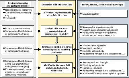
Fig.1.Workflow of the integrated approach to estimate the in situ stress field around a large deep underground cavern group near a river valley.Assumption 1:The regressed in situ stress field based on the available in situ stress measurements is reliable in terms of its magnitude.Principle 1:The principal stress magnitudes remain unchanged while the principal stress orientations are varied during the modification of the regressed in situ stress field.EDZ means excavation damaged zone.
2.2.Inference of the regional tectonic stress field direction
The tectonic stress field direction in the region where the cavern group is located is inferred as follows:
(1) Analyze the geological age of the regional tectonic framework to determine the primary controlling faults in the region;
(2) Identify the primary controlling fault types (such as normal faults,reverse faults,and strike-slip faults)to determine the current tectonic stress field direction;
(3) Verify the tectonic stress field direction based on the regional crustal deformation velocity map;and
(4) Assess the influence of overburden unloading on the in situ stress field rotation via a topographic analysis and determine the necessity of performing in situ stress field regression based on a numerical model that captures the topography of the region.
2.3.Analyses of in situ stress characteristics and measurement reliability
The in situ stress field characteristics of the project site can be preliminarily analyzed based on the in situ stress measurements collected on site.The measured trends and plunges of the principal stresses are depicted using a stereographic projection map.Then,the spatial relationship between the measured principal stress orientations and the tunnel/cavern axes can be determined,and the locations of potential stress-induced brittle failures can be inferred in accordance with this relationship.The measured principal stress magnitudes can be used to preliminarily judge whether the engineering site is located within a high-geostress zone or not.The reliability of the in situ stress measurements was examined as follows:
(1) Check the orthogonality of the three principal stress orientations from the measured complete stress tensor(six components) based on the stereographic projection map (Feng and Hudson,2011);
(2) Check the macroscopic consistency between the trends of the measured major principal stresses and the regional tectonic stress direction;
(3) Check the consistency between the locations of actual stressinduced brittle failures and the locations inferred from the spatial relationship between the principal stress orientations and the tunnel/cavern axes;
(4) Compare the measured major principal stress magnitudes and the back-analyzed threshold of the major principal stress magnitudes for stress-induced brittle failures according to the strength-stress ratio criterion and the uniaxial compressive strength of the rock at the site;and
(5) Check the differences between in situ stress measurements at neighboring points to judge the influence of the geological structures on the in situ stress measurements.
2.4.Regression-based in situ stress field analysis and reliability assessment
Multiple linear regression coupled with linearly elastic 3D numerical simulation was adopted to acquire the 3D in situ stress field based on the available in situ stress measurements.In this method,the in situ stress field was classified into the following seven tectonic actions:gravity,compression in the x-direction (Fig.2a),compression in the y-direction(Fig.2b),shear in the x-y plane(Fig.2c),shear in the y-x plane(Fig.2c),shear in the y-z plane(Fig.2d),and shear in the x-z plane(Fig.2e).The influences on the in situ stress field of all these tectonic action factors except gravity were implemented by applying specified displacements at the boundaries.The in situ stress field [^σ] was thus obtained as a linear superposition of the stress fields induced by the above seven tectonic actions (Eq.(1)):

where ux,uy,uxy,uyx,uyz,and uxzare the stress fields induced by compression and shear under unit displacements;ugis the stress field induced by gravity;e is the error;and [a1a2a3a4a5a6a7] is the matrix composed of the seven regression weight coefficients of the tectonic action factors.
The method was carried out via the following steps(Zhang et al.,2012):
(1) Step 1:Analyze the influences of the seven tectonic action factors on the in situ stress field and express them in the form of boundary and initial conditions;
(2) Step 2:Establish a 3D mesh model that includes the major geological structures in the region and considers the topography of the project site;
(3) Step 3:Apply the numerical schemes corresponding to each tectonic action factor using a numerical analysis method(e.g.the finite element method or finite difference method) in combination with an interpolation method to compute the six stress components for each scheme at all measuring points;
(4) Step 4:Solve the weights of all tectonic factors using the least squares method by minimizing the errors between the calculated and measured stress components;and
(5) Step 5:Compute the products of the weights and the boundary and initial conditions formulated for all tectonic factors in Step 1 to obtain the superimposed boundary and initial conditions,then reapply them to the 3D numerical model to solve the regressed in situ stress field.
Linearly elastic numerical simulation via FLAC3D(Itasca,2012)was performed to model the seven tectonic actions and their superpositions to solve the regressed in situ stress fields.Elastoplastic numerical simulations based on the regressed in situ stress field were then performed to predict the EDZs of the surrounding rock mass.In these elastoplastic simulations,the mechanical model of the surrounding rock mass was changed from the linearly elastic model to the rock mass deterioration model (RDM)(Jiang et al.,2010),and the EDZs were identified by the distribution of the failure approach index(FAI)(Zhang et al.,2011;Xu et al.,2017).The RDM is primarily applied to modeling brittle failure of rock mass.This model assumes weakening of cohesion,strengthening of friction,and deterioration of elastic modulus as linear functions of rock mass equivalent plastic strains.The basic ideas of the FAI are

where σ and σpeakis the represent stress and peak strength,respectively;εpandare the plastic strain and plastic strain limit,respectively.
Eq.(2) indicates that:(1) When the value of FAI is less than 1,the rock mass is in a safe state;(2) when the value is between 1 and 2,the rock mass is in a yielding and damage state;and (3)when the value is larger than 2,the rock mass fails.As such,the EDZs can be identified by the FAI distribution by setting a FAI threshold.
The reliability of the regressed in situ stress field is primarily assessed from two perspectives:
(1) Compare the calculated and measured in situ stress components;
(2) Check the consistency between the EDZ locations predicted under the regressed in situ stress field and the locations of the actual stress-induced brittle failures observed during the excavation of small tunnels or the initial excavation of the large deep underground cavern group.
2.5.Modified in situ stress field analysis and reliability verification
For overcoring method,the imprecision of the principal stress orientations is larger than that of the principal stress magnitudes(Sjöberg and Klasson,2003).For HF method,one principal stress is assumed to be parallel to the borehole axis (Haimson and Cornet,2003),implying that the accuracy of the principal stress orientations depends on the accuracy of the borehole axis orientation,perhaps also leading to greater imprecision of the principal stress orientations than that of the principal stress magnitudes.The in situ stress measurements obtained via overcoring and HF methods,as suggested by the International Society for Rock Mechanics and Rock Engineering (ISRM),are thus more acceptable in terms of magnitude than in terms of orientation.Therefore,the regressed in situ stress field based on the available in situ stress measurements is assumed to be reliable in terms of magnitude.Based on this assumption,the following basic principle was proposed to modify the regressed in situ stress field:the principal stress magnitudes should remain unchanged,while the principal stress orientations can be varied.
According to the theory of elasticity(Poulos and Davis,1974),the expressions for solving for the magnitudes of the major principal stress σ1,the intermediate principal stress σ2,and the minor principal stress σ3are as follows:

Fig.2.Schematic diagrams of the tectonic actions:(a)compression in the x-direction,(b)compression in the y-direction,(c)shear in the horizontal plane,(d)shear in the x-z plane,and (e) shear in the y-z plane.
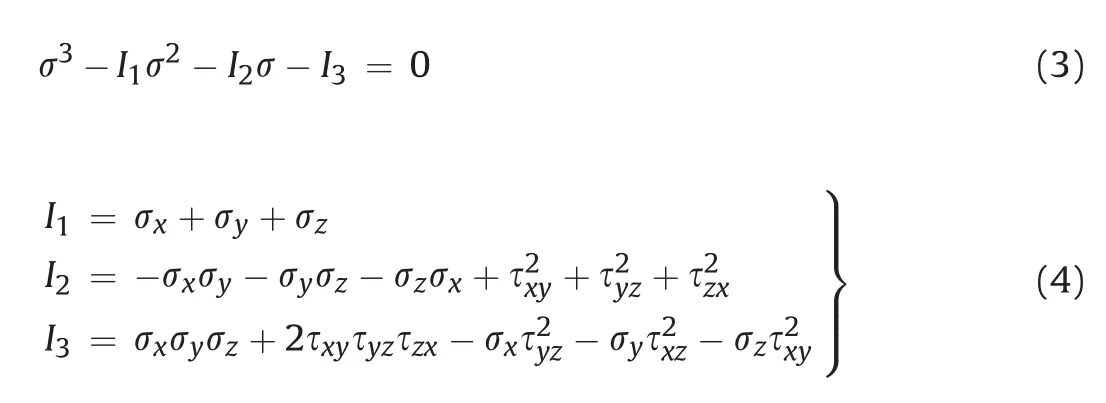
where σx,σy,σz,τxy,τyz,and τzxare the stress components in the xy-z coordinate system;and I1,I2,and I3are the first,second,and third stress tensor invariants,respectively.The principal direction cosines of the stress tensor in the x-,y-,and z-directions,i.e.li,mi,and ni(i=1,2,and 3),are


According to Eqs.(3)-(7),the principal stress orientations can be changed without changing the magnitudes by simultaneously assigning opposite values to two of the three shear stress components in the regressed in situ stress field.The reliability of the modified in situ stress field in terms of principal stress orientations was confirmed by comparing the locations of the predicted EDZs with that of the actual stress-induced brittle failures observed during the excavations of small tunnels or the initial excavations of the large deep underground cavern groups.The reliability of the modified in situ stress field in terms of the principal stress magnitudes was verified by comparing the estimated and actual depths of stress-induced brittle failures (spalling) observed during small tunnel excavations.The spalling depth Sd(cm) of a small tunnel/cavern was estimated using the following empirical equation proposed by Martin and Christiansson (2009):

where a(m)is the cavern radius or the effective tunnel radius;σsmis the rock mass spalling strength,which is equal to 0.4-0.6 times the uniaxial compressive strength of rock σc;and σθis the maximum tangential elastic stress,which,for a circular cavern in a continuous,homogeneous,isotropic,and linearly elastic rock mass,can be calculated using the Kirsch equations for plane strain,i.e.Eq.(9) (Goodman,1989).For a noncircular cavern,σθcan be determined by numerical analysis.

3.Overview of the Shuangjiangkou underground cavern group
3.1.Project layout
The Shuangjiangkou hydropower project is located approximately 2-6 km below the intersection of the Zumuzu River and the Chuosijia River in the upper reaches of the Dadu River in Maerkang County and Jinchuan County,Aba Prefecture,Sichuan Province,China.The cavern group for the hydropower project is built in a mountain with a height of greater than 1000 m near the Dajinchuan River valley (Fig.3a).This cavern group is composed of three parallel main caverns (i.e.the main powerhouse,main transformer,and tailrace surge tank caverns)and several auxiliary tunnels,such as generatrix and tailrace tunnels.The dimensions of the main powerhouse,main transformer,and tailrace surge tank caverns are 219.5 m(length)×28.3 m or 25 m(span)×68.3 m(height),158.3(length) m × 19.5 m (span) × 25.4 m (height),and 37 m(length)×20 m(span)×75.5 m(height),respectively(Fig.3b).The axes of the three main caverns all trend N10°W.The depth of the cavern group is 320-500 m.The horizontal distances between the cavern group and the mountain slopes are 400-640 m.
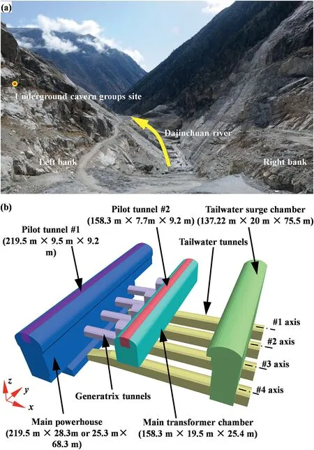
Fig.3.Overview of the Shuangjiangkou underground cavern group:(a)location of the project site and topography of the river valley and(b)excavations for the cavern group.The coordinate system was defined such that the positive x-direction points east,the positive y-direction points north,and the positive z-direction points up.
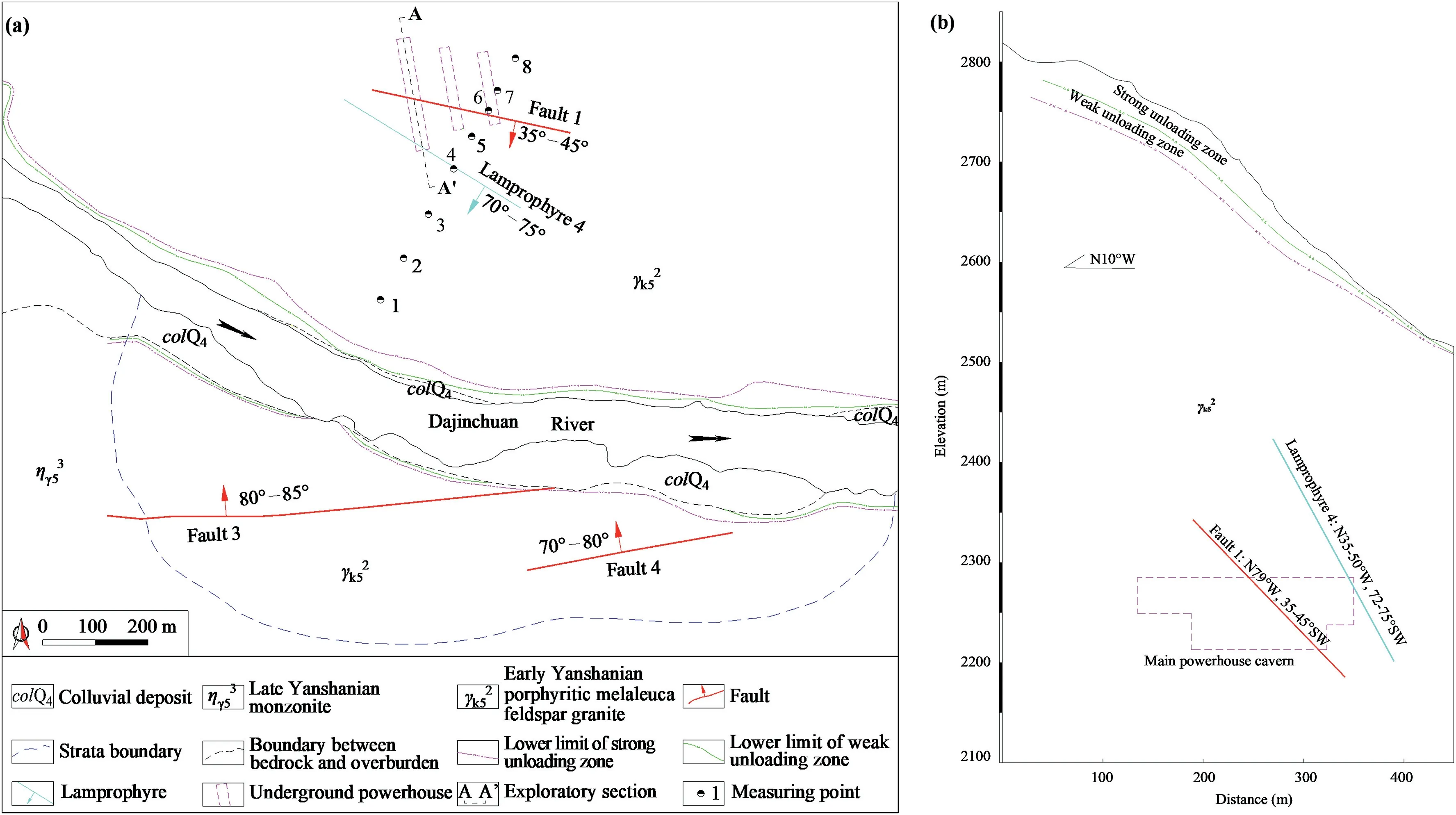
Fig.4.Engineering geological sections:(a) Horizontal section (plane view) at 2264 m and (b) Longitudinal section along the axis of the main powerhouse cavern (A-A′ section).
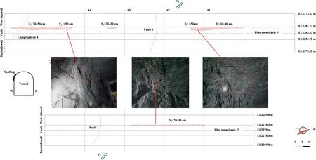
Fig.5.Spalling in the pilot tunnels in the Shuangjiangkou underground cavern group.
3.2.Geological characteristics
The rock mass surrounding the cavern group is composed of Yanshanian medium-coarse porphyritic biotite-K-feldspar granite(γ2k5) (see Fig.4).Pegmatite veins with thickness of less than 1 m and length of 3-10 m are randomly mixed into the granite in the form of veins,bands,and block shapes.The surrounding rock mass is hard and continuous,with few joints and fractures.Secondary inactive faults exposed at the hydropower project site include Fault 1 (N79°W,35°-45°SW),Fault 3 (N75°-85°E,80°-85°NW),and Fault 4 (N70°-80°E,70°-80°NW).A lamprophyre vein (N35°-50°W,72°-75°SW;Lamprophyre 4) (see Fig.4) was also found at the cavern group site.The P-wave velocity in the surrounding rock mass is greater than 5000 m/s.The mean σcat the site is 139 MPa.
3.3.In situ stress measurement and spalling during pilot tunnel excavation
The overcoring method was used to perform in situ stress measurements at points 1,2,3,5,7,and 8,and HF was performed at points 4 and 6 in an exploratory tunnel at 2268 m(see Fig.4a).This exploratory tunnel is not completely located within the excavation range of the cavern group,suggesting that the corresponding in situ stress measurements cannot provide a complete picture of the in situ stress field around the cavern group due to the small measurement range and the limited number of measuring points.Many spalling veins with Sdvalues between 10 cm and 50 cm formed along the west arch shoulder during pilot tunnel excavation for the cavern group (see Fig.5),indicating that (1) the cavern group is located in a high-geostress zone;(2)the in situ stress directions at the site are relatively consistent;and(3)certain parts of the cavern group may experience serious failure due to subsequent excavation without prior reinforcement.
4.3D in situ stress field estimation for the Shuangjiangkou underground cavern group
4.1.Inferring the regional tectonic stress direction
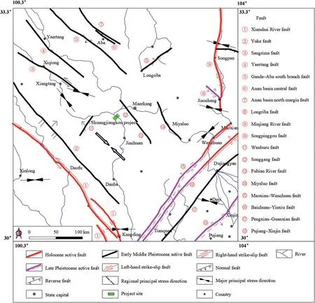
Fig.6.Regional tectonic framework around the Shuangjiangkou project site (adapted from Kan et al.,1977).
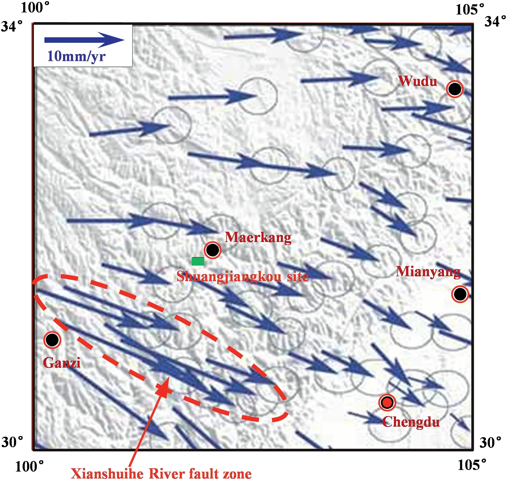
Fig.7.Regional crustal horizontal deformation velocity around the Shuangjiangkou project site (adapted from Li et al.,2003).
The Shuangjiangkou hydropower project site is located at the eastern edge of the Qinghai-Tibet Plateau,which has been tectonically active since the Cenozoic era.Due to the northward movement of the Indian plate,the Sichuan-Qinghai plate moved southeast along well-developed faults (Fig.6).Many large faults,such as the Xianshui River fault and the Minjiang River fault,were active in the Late Quaternary and Holocene.Differences in horizontal movement rates around the project site are small,and the horizontal crustal movement rate of the Xianshui River fault(10±2 mm/a)is the highest(Fig.7).The project site is located in the region with good plate integrity.The crustal deformation of the Xianshui River fault zone is the severest in the region.Therefore,the Xianshui River fault is regarded as the primary control structure in the region.The regional tectonic stress direction around the project site can be inferred by analyzing the formation mechanism of the Xianshui River fault.The Xianshui River fault is a steeply dipping left-handed strike-slip fault with an orientation of N40°-50°W and 60°-80°NE,indicating that the direction of the tectonic stress acting on the fault zone is generally parallel to the strike of the fault(i.e.N40°-50°W).
4.2.Analysis and reliability examination of the in situ stress measurements
Lower-hemisphere stereographic projections(see Fig.8a)of the in situ stress measurements (see Table 1) show that:(1) the orientations of the three principal stresses at each measuring point are mutually orthogonal,indicating no technical errors in the measurement process;(2)the major,intermediate,and minor principal stresses trend SSE (10°-40°),SWW (50°-90°),and NNE-NEE(20°-60°),respectively;and (3) the major and intermediate principal stresses have plunges ranging from 7°to 35°,while the plunge of the minor principal stress ranges from 38°to 66°.Although the measured major principal stress trend and the regional tectonic stress field direction are both macroscopically S-E,there is still a significant difference between them:the former is S10°-40°E,and the latter is N40°-50°W (i.e.S40°-50°E).The reason for this difference is that the major principal stress in the in situ stress field around the cavern group has rotated due to overburden unloading induced by fluvial erosion.
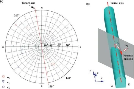
Fig.8.Orientations of the measured 3D principal in situ stresses around the Shuangjiangkou underground cavern group:(a) Lower-hemisphere stereographic projection,and (b)Spatial relationship between the orientation of the major principal stress and the tunnel axis.

Table 13D principal in situ stresses at the measuring points around the underground powerhouse(with the up-dip angle as positive).

Table 2Stress components at the measuring points in the global coordinate system.
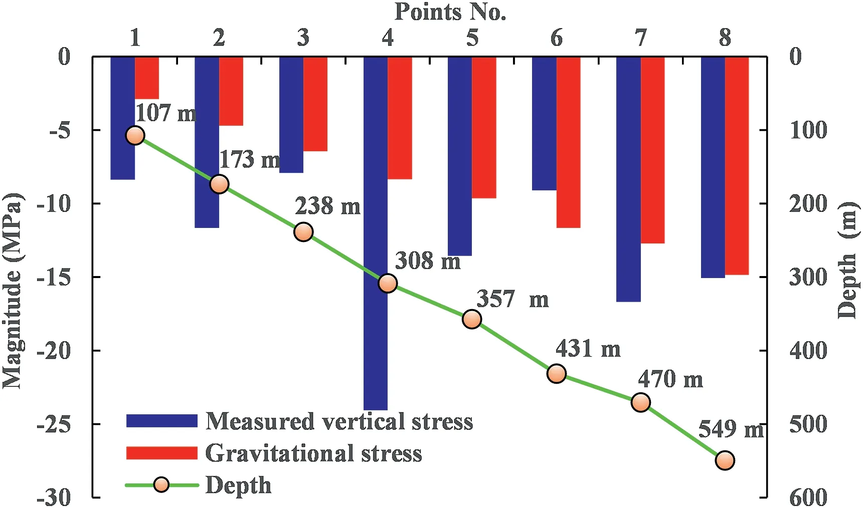
Fig.9.Measured gravitational stresses versus depth at various measuring points.
The magnitudes of the major,intermediate and minor principal stresses around the cavern group are 16-38 MPa,8.5-20 MPa,and 3-11 MPa,respectively (see Table 1).The magnitudes of the three principal stresses differ greatly,indicating that the impact of the major principal stress is much more significant than that of the intermediate principal stress in terms of spalling.The strength-stress ratio σc/σmaxis calculated using a σcof 139 MPa and a σmaxof 15-36 MPa,equal to the projection of the major principal stress onto the axis,and ranges from 3.9 to 9.3.The value of σc/σmaxindicates that the cavern group is located within a high-geostress zone,and stress-induced brittle failures (slight rockbursts and spallings) are possible during excavation of the cavern group according to the Chinese national standard GB/T 50218-2014 (2014).The rock mass failure type predicted by this criterion is in good agreement with the actual situation on site,indirectly proving that the measured major principal stress magnitudes are generally reliable.Note,however,that this is only a preliminary judgment on the reliability of all major principal stress magnitudes;the reliability of each measured principal stress magnitude requires further analysis based on other information and general knowledge of engineering geology.
According to the spatial relationship between the measured major principal stress orientations and the axes of the pilot tunnels,it can be inferred that spalling veins are expected to form at the east arch shoulders of the pilot tunnels during excavation (Fig.8b).However,these inferred spalling veins are not consistent with the observed spalling veins at the west arch shoulders of the pilot tunnels(Fig.5),indicating that the measured major principal stress plunges do not match the actual in situ stress field.
The measured vertical stresses are greater than the gravitational stresses at all measuring points except Point 6 (see Table 2 and Fig.9) and do not increase with increasing depth.Two inferences can be drawn from these phenomena:(1)the cavern group site has been subjected to significant overburden unloading induced by fluvial erosion,and(2)the overburden unloading is not consistent among all measuring points because the erosion thickness of the overburden near each measuring point is different due to topographic differences.After the ancient planation surface at this site was eroded by the river to form a deep valley,the ancient gravitational stress field was locked into the existing relatively intact rock masses far from the surface weathering zone and unloading zone,resulting in greater vertical stresses(σz)than those expected at a given depth (i.e.the gravitational stress σz′).Therefore,it is illogical that the value of measured vertical stress was less than that of the gravitational stress at Point 6.However,the in situ stress at Point 6 was measured via HF method,which requires that the measured rock mass should be homogeneous,isotropic,and linearly elastic (Haimson and Cornet,2003),whereas the Point 6 borehole is relatively close to Fault 1(see Fig.4a),which may have served as a geological factor leading to abnormal measurements.The in situ stress measurement at Point 4 was also confirmed to be unreliable by the ratio of the measured vertical stress to the gravitational stress,which is equal to 2.89,whereas the ratios for neighboring points at the same elevation (Points 3 and 5) located within an intact and homogeneous rock mass range from 1.23 to 1.46.As in the case of HF method,a continuous,homogeneous,isotropic,and linearly elastic rock mass is needed to employ the overcoring method(Sjöberg et al.,2003);however,the rock mass at Point 4 is cut by Lamprophyre 4 (Fig.2),which may result in unreliable measurements.
4.3.Regression and modification of the 3D in situ stress field
4.3.1.3D geometric model
A 3D geometric model considering the topography and major geological structures that may affect the stability of the surrounding rock mass(i.e.Fault 1 and Lamprophyre 4) was established for the regression and modification of the in situ stress field using numerical simulations (Fig.10).The lengths of the model in the xand y-directions are 700 m and 1020 m,respectively.The length in the z-direction is equal to the altitude difference between an elevation (2000 m) and the summit of the mountain,approximately 990 m.To enable assessment of the reliability of the regressed in situ stress field,the model includes all step excavations for the cavern group,which correspond to the actual excavation sequences.The excavation footage along the tunnel/cavern axis is 10 m according to the actual excavation progress.The input parameters for the numerical simulations are listed in Table 3.Note that the negative influence of the pegmatite veins on the mechanical properties of the granite(Shang,2020)was considered in the form of weakened mechanical parameters.
4.3.2.Reliability assessment of the regressed in situ stress field
The stress components at Points 1,2,3,5,7,and 8(Table 2)were used in the regression of the in situ stress field,whereas the stress components from Points 4 and 6 were excluded because the corresponding measurements were considered suspect.The matrix of the regression weight coefficients obtained using the least squares method is

The multiple linear regression coefficient R is 0.94,and the residual sum of squares Q of the regression is equal to 294.3.The estimated average standard error is 3.24 MPa,and the F-check observation value is F=32.2.The critical value Fα(7,36-7-1) at a significance level of α=0.05 is 2.359.F>Fα,indicating that the overall effect of the seven independent boundary loads on the in situ stressfield is significant and that the regression is ideal.The regressed in situ stress components at the measuring points are generally in good agreement with the measured in situ stress components,except for some differences in the shear stress components (Fig.11).However,the EDZs identified from the FAI distribution under the regressed in situ stress field (Fig.12a) are located at the east arch shoulders of the pilot tunnels,which are inconsistent with the actual spalling vein locations at the west arch shoulders(Fig.5).These findings indicate that the regressed in situ stress field based on the available in situ stress measurements is reliable in terms of the principal stress magnitudes and trends but unreliable in terms of plunges.
4.3.3.Modification and verification of the regressed in situ stress field
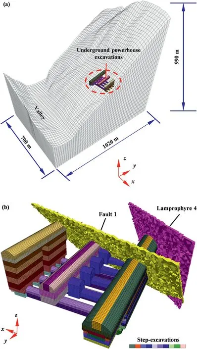
Fig.10.3D geometric model for the regression of the in situ stress field:(a) mesh model of the surrounding mountain,and (b) mesh model of the cavern group excavations and major geological structures.
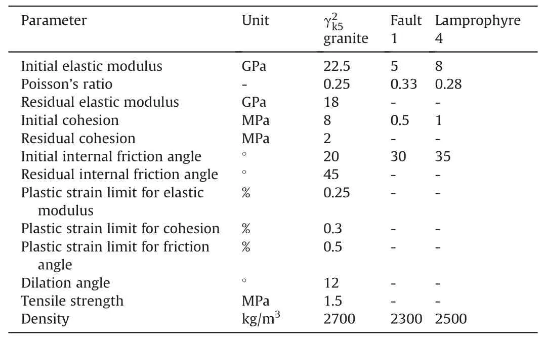
Table 3Input parameters for the numerical simulations.
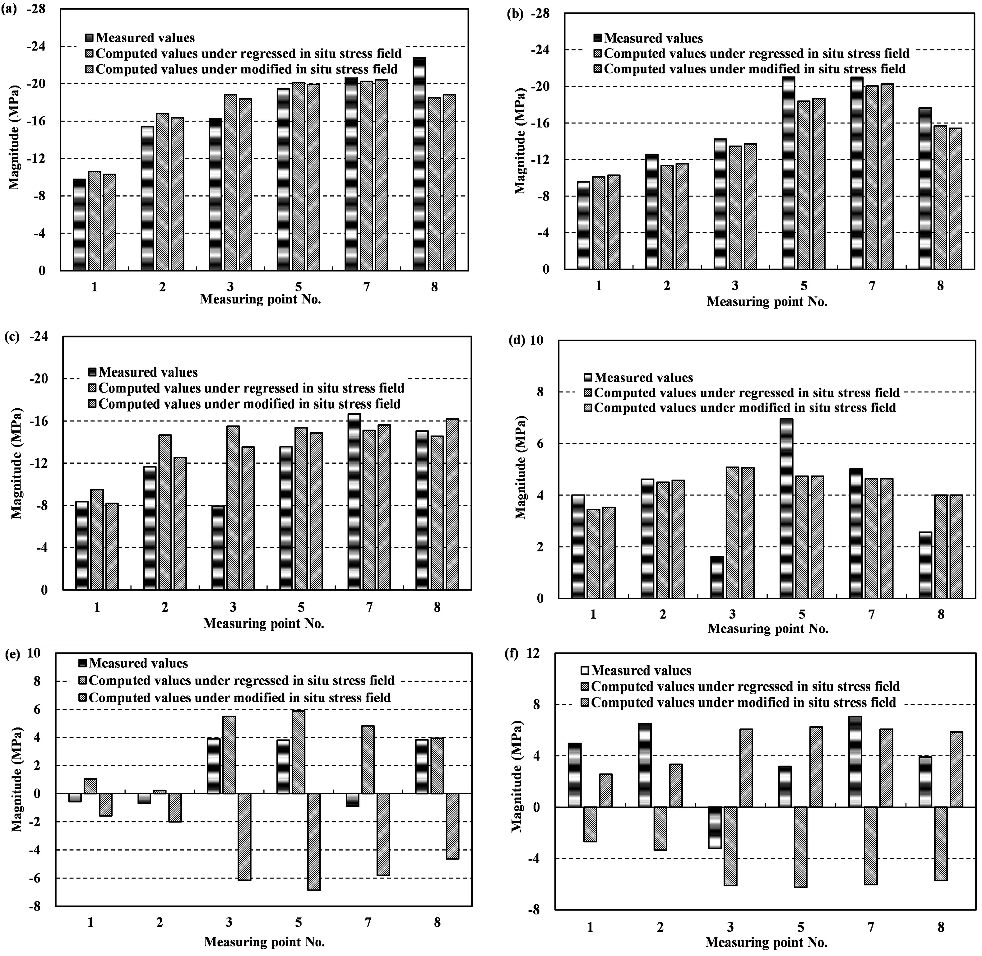
Fig.11.Comparisons between the computed and measured stress components:(a) σx,(b) σy,(c) σz,(d) τxy,(e) τyz,and (f) τxz.
To ensure that the predicted spalling matches the observation in the actual tunnels,the predicted spalling vein locations should be shifted from the east arch shoulders to the west arch shoulders of the tunnels in the numerical simulations.In other words,the major principal stress plunge in the regressed in situ stress field should be modified to be inclined toward the west sidewalls of the tunnels without changing the magnitudes and trends of the principal stresses.This modification can be realized by simultaneously changing the signs of the shear stress components in the upward direction (τyzand τxz) according to Eqs.(3)-(7).Subsequently,the modified in situ stress components at the measuring points(Fig.11)are generally close to the regressed in situ stress components in terms of their absolute values.According to the results of the elastoplastic simulation of the pilot tunnel excavation and the first step excavation of the main powerhouse under the modified in situ stress field,the EDZ locations indicated by the FAI distribution match the spalling vein locations (Figs.12b and 13),proving that the modified in situ stress field is reliable in terms of the principal stress orientations.
σsmis equal to 69.5 MPa when σsm=0.5σc(σc=139 MPa)·The a values of the pilot tunnels in the main powerhouse and main transformer caverns are 5.7 m and 5.2 m,respectively.According to the modified in situ stress field,the major principal stresses at the west arch shoulders in the main powerhouse and main transformer caverns,where the spalling veins are located,are 28.5-29 MPa and 28-28.5 MPa,respectively,and the minor principal stresses are 10.5-12 MPa and 10-11.5 MPa,respectively(Fig.14).The estimated Sdvalues in the two tunnels are 10.7-23 cm and 10-17.2 cm,respectively,according to Eq.(7);these values are generally consistent with the actual spalling depth (10-50 cm,Fig.5),indicating that the modified in situ stress field is also reliable in terms of the principal stress magnitudes.
4.4.Features of the 3D in situ stress field
4.4.1.Magnitude and orientation
The major and minor principal stress magnitudes are 25-35 MPa and 8-16 MPa,respectively (Fig.14).The σc/σmaxvalue around the cavern group is recalculated to lie within a range of 4-5.6,indicating that the cavern group resides in a high-geostress zone according to the strength-stress ratio criterion.The major and minor principal stress magnitudes vary greatly along the generator axes (Fig.14a and b),indicating that the value of σθobtained from Eq.(8) varies significantly along the generator axes.Consequently,the degree of brittle failure may vary in different locations,such as the main powerhouse,main transformer,and tailrace surge caverns.Along the axis of the main powerhouse cavern,there is little variation in the major principal stress magnitudes but significant variations in the minor principal stress magnitudes around the cavern group(Fig.14c and d).Brittle failure induced by different σθvalues may occur in different sections of the same cavern.
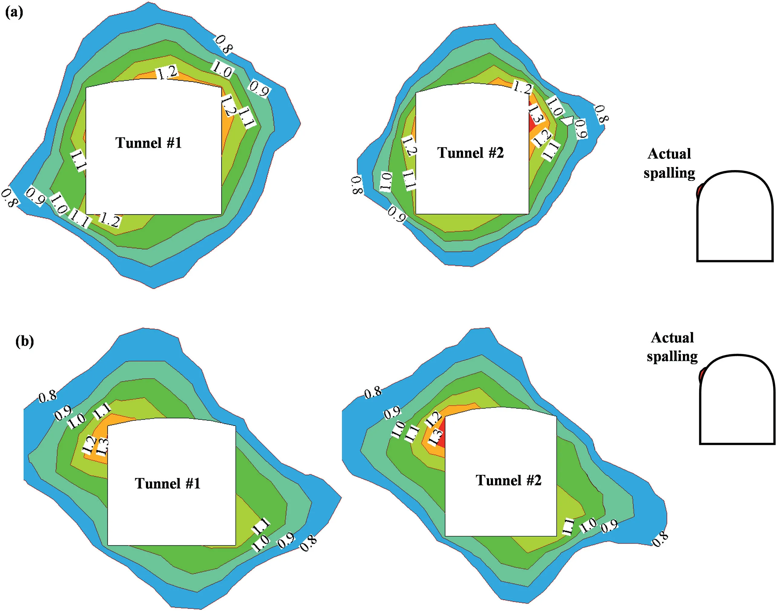
Fig.12.Pilot tunnel EDZs identified from the FAI distribution in a section along generator axis #2:(a) under the regressed in situ stress field,and (b) under the modified in situ stress field.

Fig.13.Comparison of the EDZs identified from the FAI distribution under the modified in situ stress field and the actual spalling veins observed after the first step excavation of the main powerhouse cavern.
The major principal stress around the cavern group generally trends NNW (Fig.15a).The major principal stress at the crosssection along the generator axis plunges toward the west sidewalls of the main caverns with an inclination of 30°-40°(Fig.15b),while the major principal stress in the longitudinal section along the axes of the main caverns plunges away from the valley with an inclination of 30°-40°(Fig.15c),which explains why spalling veins have consistently formed at the west arch shoulders of the pilot tunnels.
4.4.2.Distribution features
The lateral pressure coefficients are defined as λx=σx/σzand λy=σy/σz.The values of λxand λyfor the section along the axis of the main powerhouse cavern are 0.9-1.5 and 0.8-1.4,respectively(see Fig.16).λxand λyare both significantly greater than the lateral pressure coefficient λ of the gravitational stress field (λ=ν/(1 -ν)=0.33 when the Poisson’s ratio ν of the rock mass is 0.25),indicating that the in situ stress field around the cavern group is significantly affected by the tectonic stress field.
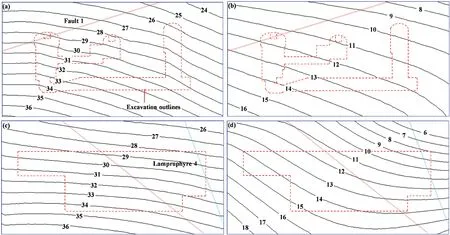
Fig.14.Principal stress (in MPa) distribution characteristics at typical cross-sections around the cavern group:(a) major principal stress for a section along generator axis #2,(b)minor principal stress for a section along generator axis#2,(c)major principal stress for a section along the axis of the main powerhouse cavern,and(d)major principal stress for a section along the axis of the main powerhouse cavern.
The variation curves of the lateral pressure coefficients with depth for the cross-section along generator axis #2 around the main powerhouse(see Fig.17)show that(1)the values of λxand λyincrease significantly with depth;(2) λxand λyare significantly greater than λ (=0.33);and (3) the variation in λywith depth(0.84-1.57) is greater than the variation of λxwith depth (1.15-1.35).These observations indicate that (1) the cavern group is located within a transition zone from a gravitational stress field to a tectonic stress field,because the λxand λyvalues of the in situ stress field are overly sensitive to depth;(2)the in situ stress field around the cavern group is significantly affected by overburden unloading induced by fluvial erosion;and(3)the topography(i.e.the variation in depth) has a greater impact on the horizontal stress in the S-N direction than on the horizontal stress in the E-W direction.
5.Discussion
5.1.Suggestions for drilling and exploratory tunnel arrangement
The simulation of the 3D in situ stress field based on in situ measurements is a means to gain a deeper understanding of the in situ stress field at a specific engineering site.Accordingly,ensuring the accuracy and representativeness of the in situ stress measurements is necessary for acquiring a reliable in situ stress field.The ideal strategy for achieving this purpose is that researchers should participate in all aspects of the field investigation,from borehole and exploratory tunnel arrangements to borehole drilling and exploratory tunneling,which will be helpful for acquiring useful in situ rock mass responses during drilling and tunneling (such as borehole breakouts and stress-induced brittle failures in the exploratory tunnels) in addition to in situ stress measurements.
When the in situ major principal stress orientation is inferred in reverse from the locations of stress-induced brittle failures in the exploratory/pilot tunnels,the reliability of this inference needs to be verified.For example,under the assumptions that the magnitude of major principal stress is much greater than that of the intermediate principal stress in the in situ stress field and that the angle between the major principal stress trend and the tunnel axis is large,two major principal stress trends (i.e.NNW and SWW) with the same plunges (Fig.18) may be inferred from the spatial relationship between the brittle failures and the tunnel axes.By contrast,under the same in situ stress field,when brittle failures occur at the west arch shoulder of the main tunnel and at the north arch shoulder of a branch tunnel perpendicular to the main tunnel,a unique in situ major principal stress orientation(NNW) can be inferred from the stress-induced brittle failure locations in these two intersecting tunnels (Fig.19).Therefore,two or more intersecting exploratory/pilot tunnels,as opposed to one or more parallel tunnels,are recommended to be located within the excavation range of the cavern group during exploratory tunneling to survey the engineering geological conditions of the project site;this strategy will significantly contribute to reducing misjudgment of the in situ principal stress orientations.For the Shuangjiangkou underground cavern group,the reliability of the modified in situ stress field in the present study has been verified based only on the brittle failures observed in two parallel pilot tunnels;thus,it is possible that the in situ principal stress orientations have been misidentified.Subsequently,the in situ stress field should be further verified based on brittle failures in other tunnels (e.g.generatrix tunnels) that intersect these parallel tunnels.
5.2.Suggestions for the numerical simulation strategy for the 3D in situ stress field
The purpose of in situ stress field estimation is not to reproduce the formation process of the regional in situ stress field.Therefore,simple rock mechanical models and fitting methods are suggested to reduce the uncertainties caused by the boundary assumptions and mechanical models adopted in the regression and modification of the 3D in situ stress field.From the perspective of the in situ measurements and brittle failure observations acquired from the tunnels excavated prior to the step excavation of a large deep underground cavern group,the available in situ stress information is incomplete due to the large excavation range and the numerous step excavation processes for the cavern group.The 3D in situ stress field that has been modified based on the incomplete in situ stress information available at the current excavation stage is only the most reliable estimate available before the next excavation stage.Therefore,continuous and dynamic modification of the in situ stress field based on the brittle failures and monitoring information collected during step excavation should serve as a basic principle for estimation of the 3D in situ stress field around a large deep underground cavern group.
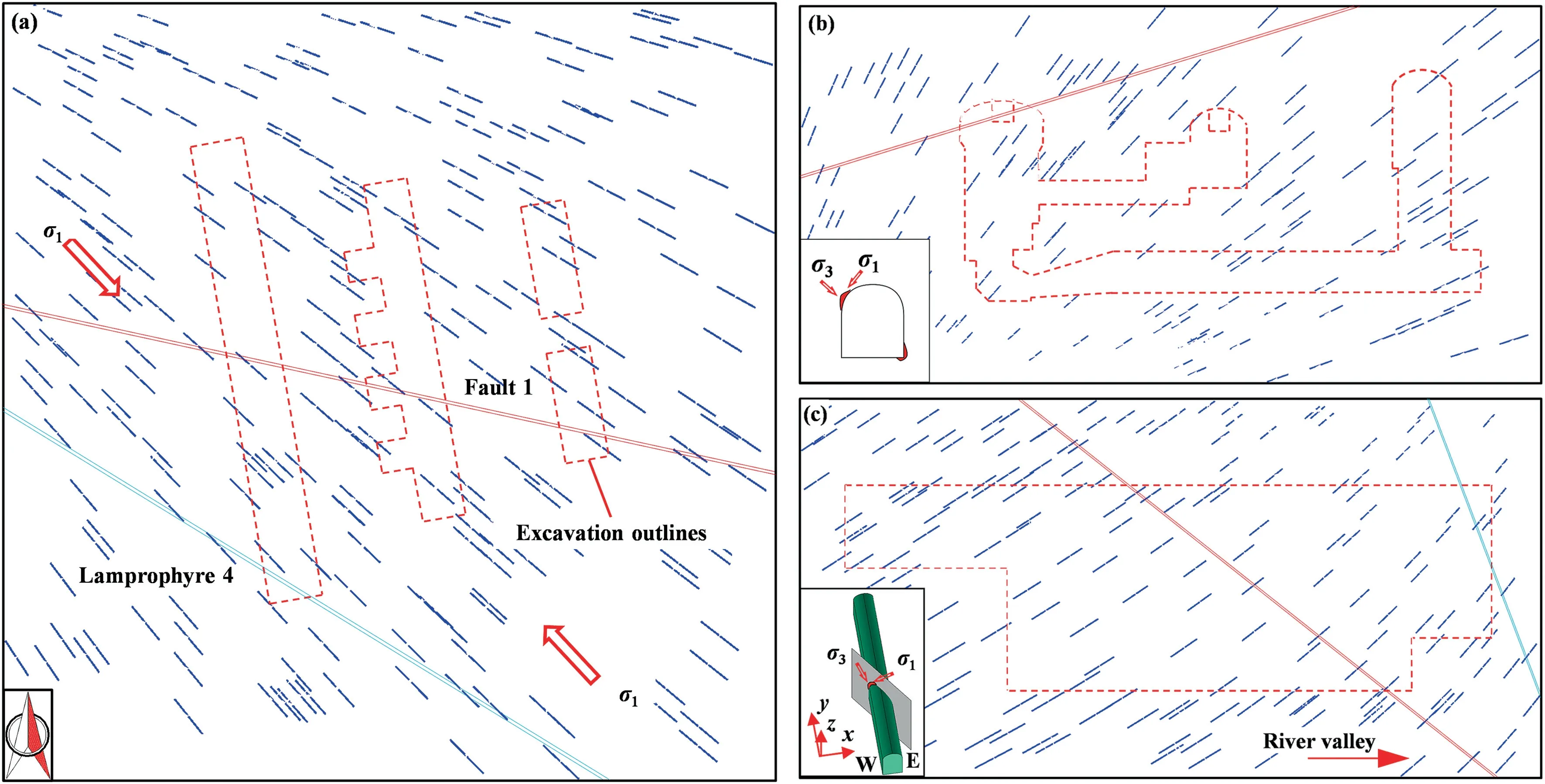
Fig.15.Major principal stress tensors in typical sections around the cavern group:(a) horizontal section at 2264 m,(b)cross-section along generator axis#2,and(c)longitudinal section along the axis of the main powerhouse cavern.
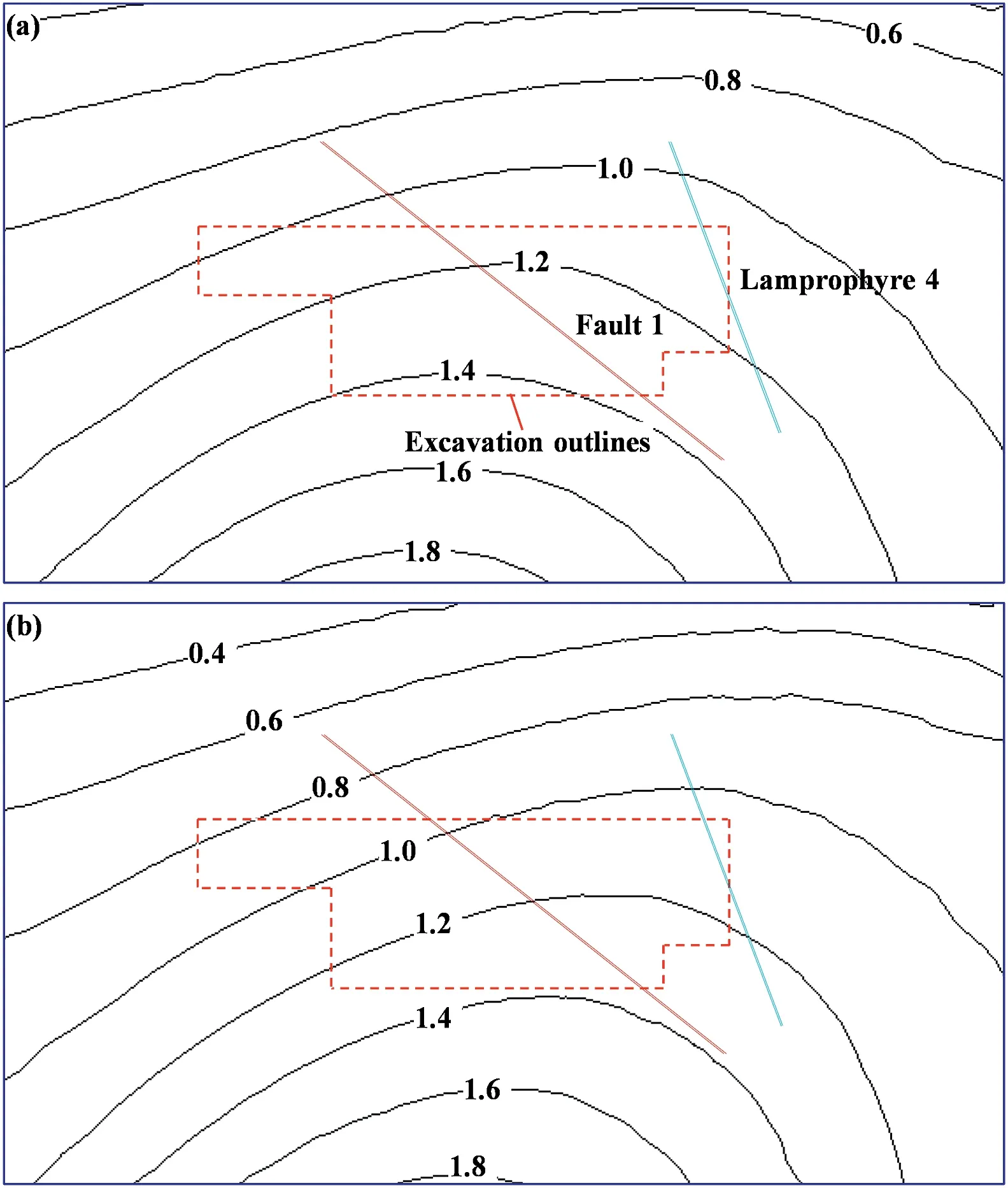
Fig.16.Lateral pressure coefficient distributions along the axis of the main powerhouse cavern:(a) λx and (b) λy.
5.3.Rationality of the major principal stress plunge in the Shuangjiangkou underground cavern group
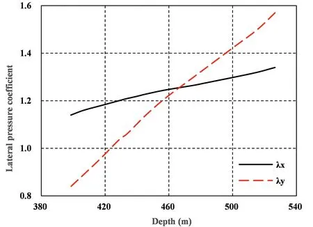
Fig.17.Variation of the lateral pressure coefficients with depth for a cross-section along generator axis #2 of the main powerhouse cavern.
The orientation of the in situ stress field in and around a deep valley is controlled by the valley topography.The in situ stress field is significantly affected by overburden unloading induced by fluvial erosion,resulting in a variation in the plunge of the major principal stress from the horizontal direction to an inclined direction pointing toward the valley along the mountain slope (Bai and Li,1982;Pan and Amadei,1993).The in situ stress field around the Shuangjiangkou underground cavern group seems to not conform to this rule;however,the cavern group is located at the edge of a mountain with three sides affected by overburden unloading due to fluvial erosion (see Fig.20).Because the depths of the three river valleys near the project site are approximately the same according to the topographic analysis,this indicates that the unloading capacity induced by erosion due to the Chuosijia and Zumuzu Rivers is greater than that induced by the Dajinchuan River,leading to a major principal stress plunging toward the intersection of the Chuosijia and Zumuzu river valleys.Therefore,the plunge of the major principal stress around the cavern group as determined in this study is consistent with the general rule for in situ stress fields near deep valleys.
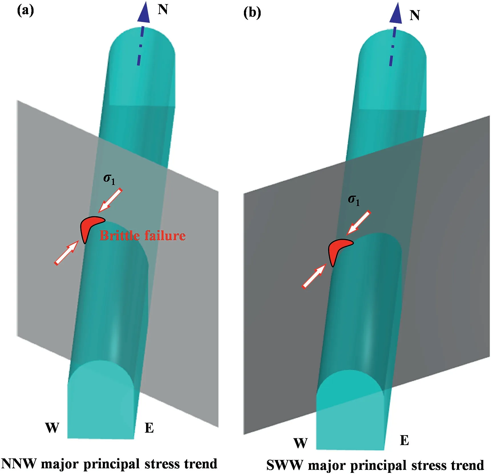
Fig.18.Illustration of the inference of the in situ major principal stress orientation according to the spatial relationship between the locations of stress-induced brittle failures in a tunnel and the tunnel axis:(a)a NNW major principal stress trend,and(b)a SWW major principal stress trend.
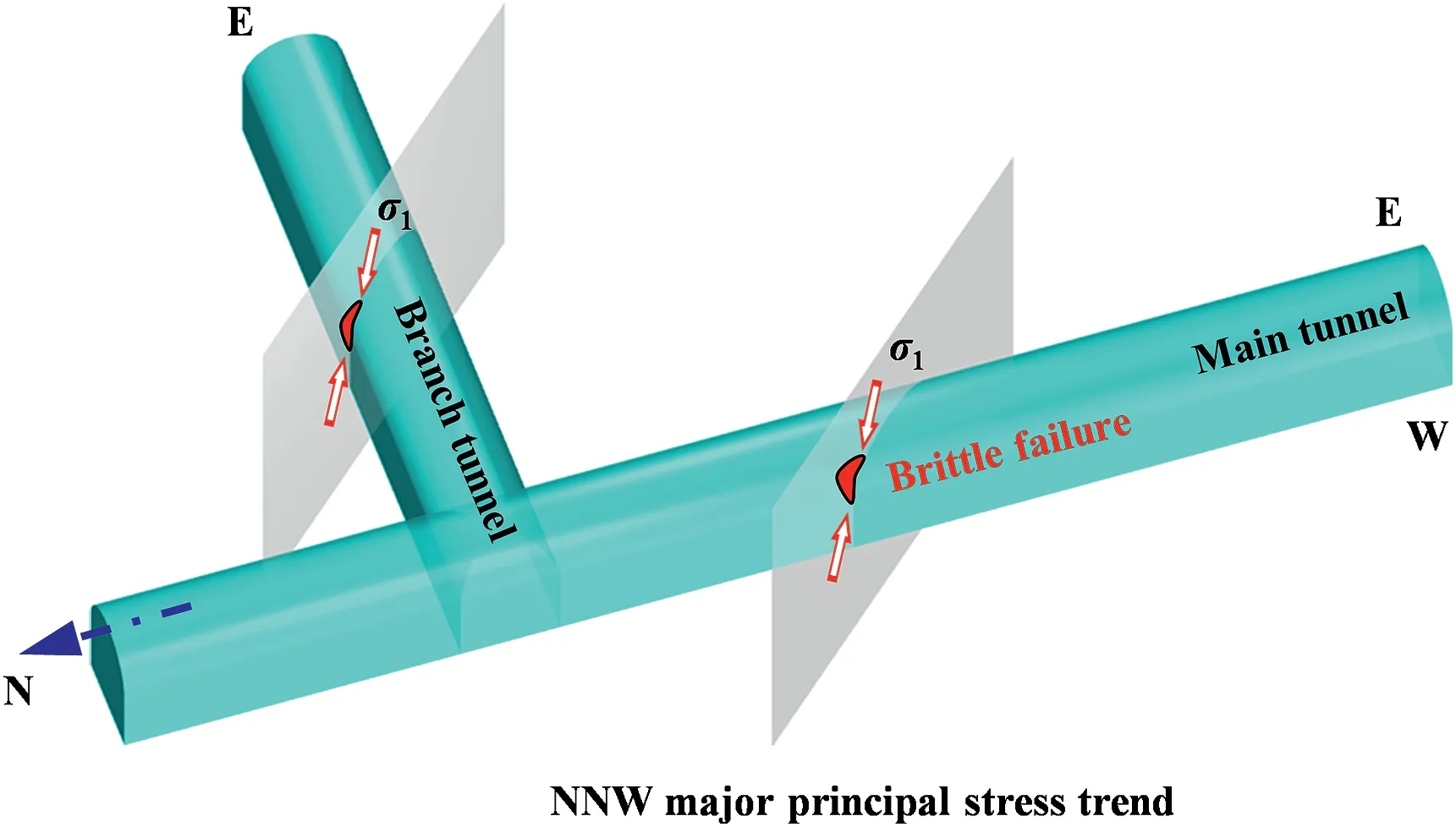
Fig.19.Illustration of the inference of the in situ major principal stress orientation according to the spatial relationship between the locations of stress-induced brittle failures in two intersecting tunnels and the tunnel axes.
6.Conclusions
In this study,an integrated approach for estimating the 3D in situ stress field around a large deep underground cavern group near a valley was developed based on incomplete in situ stress measurements and the stress-induced failure of small tunnels excavated prior to the step excavation of the cavern group.The application of this integrated approach to the case of the Shuangjiangkou underground cavern group demonstrates that the developed approach is reliable for estimating the in situ stress field around a large deep underground cavern group near a valley.The features of the 3D in situ stress field around the cavern group were analyzed and obtained as follows:
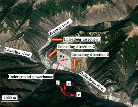
Fig.20.Current topography of the Shuangjiangkou project site.
(1) The cavern group residing in a high-geostress zone is composed of a gravitational stress field and a tectonic stress field.The in situ stress field is significantly affected by overburden unloading induced by fluvial erosion.
(2) The major principal stress trends NNW and exhibits a moderate plunge inclined toward the west sidewall of the main powerhouse cavern,indicating that stress-induced brittle failures may occur at the west arch shoulders and the lower parts of the east sidewalls in the main underground caverns during subsequent excavations.
The present study concentrates on the in situ stress field around the underground cavern groups within deep hard rock masses rather than within deep soft rock mass.Obviously,the methods related to the modification and verification of the in situ stress field around the cavern groups based on the large deformation of soft rock mass need to be further studied.
Declaration of competing interest
The authors declare that they have no known competing financial interests or personal relationships that could have appeared to influence the work reported in this paper.
Acknowledgments
This research was funded by the National Science Foundation of China (Grant Nos.U1765206 and 51979268) and Innovation Research Group Project of Natural Science Foundation of Hubei Province (Grant No.ZRQT2020000114).In particular,the authors also wish to thank Mr.Yuelin Xia and Mr.Di Zhang for their kind help in field investigation.
 Journal of Rock Mechanics and Geotechnical Engineering2021年3期
- Journal of Rock Mechanics and Geotechnical Engineering的其它文章
- Uncertainties of thermal boundaries and soil properties on permafrost table of frozen ground in Qinghai-Tibet Plateau
- Effect of natural and synthetic fibers reinforcement on California bearing ratio and tensile strength of clay
- Engineering and microstructure properties of contaminated marine sediments solidified by high content of incinerated sewage sludge ash
- Effects of oil contamination and bioremediation on geotechnical properties of highly plastic clayey soil
- Modification of nanoparticles for the strength enhancing of cementstabilized dredged sludge
- Rock-like behavior of biocemented sand treated under non-sterile environment and various treatment conditions
