
Analytical solution for upheaval buckling of shallow buried pipelines in inclined cohesionless soil*
2021-05-21 10:50BoHUANGJingwenLIUJiyingFANDaoshengLING
Bo HUANG,Jing-wen LIU,3,Ji-ying FAN†‡,2,Dao-sheng LING
1Institute of Geotechnical Engineering,College of Architectural and Civil Engineering,Zhejiang University,Hangzhou 310058,China
2Geoengineering Centre at Queen’s-RMC,Queen’s University,Kingston,ON,K7L 3N6,Canada
3Bureau of Housing and Urban-Rural Development of Chengdu,Chengdu 610094,China
Abstract:Upheaval buckling of pipelines can occur under thermal expansion and differential ground settlement.Research on this phenomenon has usually assumed the pipes are buried in horizontal ground.For long-distance transmission pipelines across mountainous areas,the ground surface is commonly inclined.Based on the Rankine earth pressure theory and Mohr-Coulomb failure criterion,analytical formulae for calculating the peak uplift resistance and the slip surface angles for a buried pipe in inclined ground are presented in this paper.Analyses indicate that the slip surfaces in inclined ground are asymmetric and rotate towards the downhill side.Under a shallow burial depth,the failure plane angle is highly impacted by the ground inclination.When the embedment ratio (H/D) is more than 4,the influence of the ground slope on the failure plane angle is negligible.The peak uplift resistance reduces in inclined ground,especially when H/D is less than 1.Finally,a simple equation considering the impact of ground inclination is proposed to predict the peak uplift resistance.
Key words:Shallow buried pipe;Upheaval buckling;Inclined ground;Analytical formulation;Soil deformation mechanism
1 Introduction
Long-distance pipelines characterized by large diameter,high pressure,and high transport capacity,are used worldwide as one of the most important and economical ways to transport oil and gas.In China,70% of oil and 99% of natural gas are transported through long-distance pipelines.Since some pipelines have been in service for decades,security issues have been currently receiving increasing attention,especially in mountainous areas with complicated topography (e.g.mountains,hills,and rugged plateaux).
More than 40% of the Chinese mainland area is classified as mountainous-hilly terrain.According to a survey in the 1990s,the probability of failure for a buried pipeline in the southwestern mountainous areas of China is significantly higher than that in the northern and northeastern plain areas.In eastern areas like Zhejiang province,70.4% of the land is covered by mountains/hills higher than 200 m.Some pipelines in that area unavoidably traverse through mountainous regions (e.g.the Hangzhou-Zhoushan gas pipelines).Mountainous-hilly areas are usually topographically complex since the ground inclination can exceed 30°;therefore,pipelines are buried underground for protection.Even so,under conditions of thermal expansion and differential ground settlement,upheaval buckling problem arises when the pipeline is buried in a shallow condition (Hobbs,1984;Maltby and Calladine,1995;Saeedzadeh and Hataf,2011).
The research to date on the upheaval buckling has mostly been focusing on the horizontal ground condition (Bransby et al.,2001;Huang et al.,2014;Chakraborty and Kumar,2016).According to observations in previous tests,the uplift mechanism involves a sliding block bounded between a pair of shear bands orienting at a inclination angle to the vertical (Cheuk et al.,2008;Huang et al.,2015).The uplift resistance offered by soil is highly dependent on the upward displacement,and generally consists of three components:(1) the submerged effective weight of the pipe,(2) the submerged effective weight of soil being lifted,and (3) the shearing resistance of soil in the vertical direction (Wang et al.,2012).Considering that pipe-soil interaction is influenced by many factors,such as the properties of the soil and pipe,burial depth,velocity of soil movement,and boundary conditions,numerical analysis has also been adopted to study the uplift resistance (Roy et al.,2018a,2018b).The prepeak increase and postpeak decrease responses of the load-displacement relationship observed in previous tests can be well explained by the strain-hardening and strain-softening behaviours of sand.
For the inclined ground condition,the slip mode and soil resistance for an uplift pipe might be different from those in horizontal ground,as the major principal stress axes rotate with the change of ground inclination (Terzaghi,1943).The existing design methods for a pipeline based on the horizontal ground assumption may reduce pipeline security and result in failure.
Research on soil-structure interaction in inclined ground began in 1943,when Terzaghi (1943) presented a graphical solution to the lateral earth pressure on a retaining wall for the cohesionless backfill with an inclined ground surface,based on the classical Rankine earth pressure theory.The graphical Mohr circle method has been used by many researchers to solve the soil-structure interaction problems in the horizontal or inclined ground condition (Richards Jr et al.,1990;Mazindrani and Ganjali,1997;Iskander et al.,2013;Nian and Han,2013).The research presented in this paper is a detailed analytical study on the upheaval buckling problem for shallow buried pipelines in the inclined ground condition.According to the Terzaghi graphical solution method,the Rankine earth pressure theory,and the Mohr-Coulomb law,the uplift failure mechanism and the inclination angle of the slip surface are studied in detail.The impact of ground inclination on the peak uplift resistance is discussed.Finally,a simple equation considering the impact of ground inclination is proposed to predict the peak uplift resistance and validated by centrifuge experiments.
2 Stress state at a point in inclined ground
The Rankine earth pressure theory is widely adopted to solve the problem of soil-structure interactions (e.g.earth pressure on a retaining wall).Mazindrani and Ganjali (1997) analytically studied the lateral earth pressure problem with an inclined ground surface according to the Terzaghi graphical solution method and the stress equilibrium of a soil element.In this study,the Rankine earth pressure theory was used to investigate the upheaval buckling problem of a shallow buried pipeline.At any point on the slip surface in the inclined ground,the stress states of a soil element were derived using the Mohr circle graphic method.
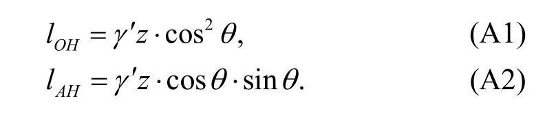
Fig.1a is a schematic of a buried pipeline within a cohesionless soil with ground inclination angleθ,effective unit weightγ′,and soil internal friction angleφ′.θis smaller thanφ′ according to the Mohr-Coulomb law.Soil is assumed to be homogeneous and isotropic.The embedment depthHis the distance between the ground surface and the crown of the pipeline,andDis the diameter of the pipeline.In Fig.1a,abcdis a soil element at depthzon a potential slip surface,and planesabandcdare parallel to the ground surface and the planesadandbcare vertical.The vertical stressσv′ acting on the planeabisγ′z·cosθ(Mazindrani and Ganjali,1997).σh′ is the stress acting on planesadandbc,and is parallel to the ground slope.According to the conjugate stress principle,stress planesabandadare conjugate planes,and the corresponding stressesσv′ andσh′ are termed as conjugate stresses.
In the initial state,the ground is under the at-rest stress condition.Once the pipeline starts to uplift,the stress conditions of the soil around the pipe begin to change (White et al.,2001).Bransby et al.(2001)pointed out that the peak uplift load is mobilized at a very small displacement of about 0.01D.Therefore,the plastic shear strain and the consequent slip surface occur when the uplift displacement of the pipeline is still very small.The whole soil block within the slip surfaces tends to be lifted with the pipeline.As the interaction between the soil on both sides of the potential slip surface reduces,the normal stress on that surface decreases.During pipeline uplifting,σv′ is assumed to be constant whileσh′ gradually decreases until the soil element on the slip surface reaches the active limit equilibrium state,then soil begins to slip.The stress state of a soil element on the slip surface at that critical moment is analyzed based on the Rankine earth pressure theory.
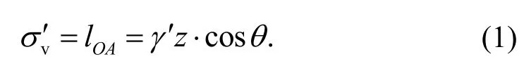
According to the pole point method,the Mohr circle for soil elementabcdis shown in Fig.1b.In the Mohr stress space (σ,τ),σ1′ andσ3′ are the maximum and minimum effective principal stresses for a soil element in the active state at the limit equilibrium,respectively.c′ is the effective soil cohesion.PointAin Fig.1b represents the vertical stressσv′ on the faceab,which equals tolOA,the length ofOA.Thus,
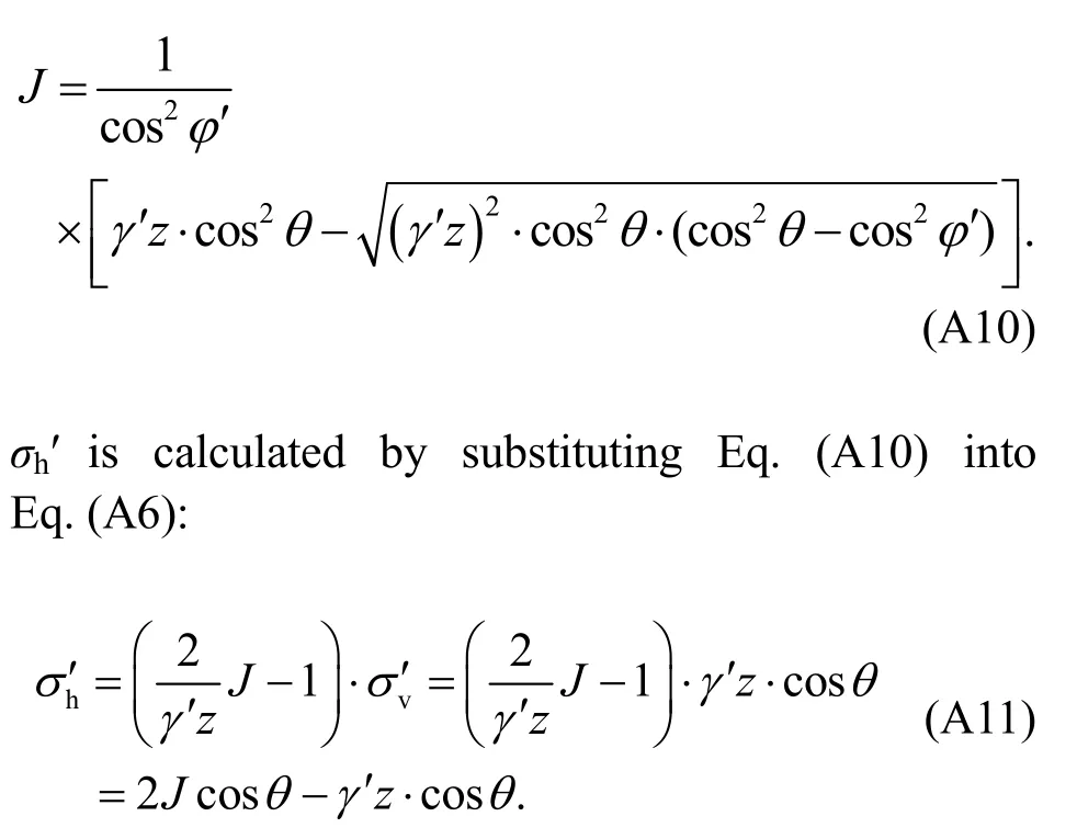
σh′ can be calculated according to the analysis elaborated in Appendix A:
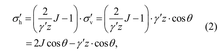
whereJ=
According to Eqs.(1) and (2),σv′ andσh′ can be predicted when the soil element reaches the active limiting equilibrium state.Consequently,the stress state on any planes within the soil element can be derived using the limit equilibrium method (Rao et al.,2016).
3 Derivation
3.1 Uplift mechanisms of a buried pipe for the horizontal ground condition
The sliding block theory,assuming that the soil block above the pipe bounded by a pair of shear bands uplifts as a whole,is widely used to predict the uplift resistance of a buried pipe.The curved slip surface is normally assumed to be plane.The error induced by this simplification is negligible and the calculated results are therefore reasonable (Ghaly et al.,1991).
Trautmann et al.(1985) presented a review of uplift solutions for anchors and pipes.The most widely used mechanism is the vertical slip model.The vertical slip model assumes that failure occurs along a pair of straight slip planes initiating from the pipe waist,and extends to the ground surface (Fig.2).The peak uplift resistance per unit length,Rpeak,is defined as the sum of the weight of the overlying soilWand the friction on the slip surfaces,wherelis the length along the vertical slip surface.The lateral forceσh′acting on the vertical failure plane is calculated by multiplying the vertical stressσv′ by the lateral stress ratioK.This vertical slip model is widely used by engineers because of its simplicity.However,as some scholars have pointed out,there is a contradiction within the model.On the vertical failure plane,σh′ is actually the minimum principal stress,so the shear stress on this plane ought to be zero (Handy,1985).The model also assumes that the lateral earth pressure is in the at-rest condition;however,the stress condition changes during the uplift process (White et al.,2001).
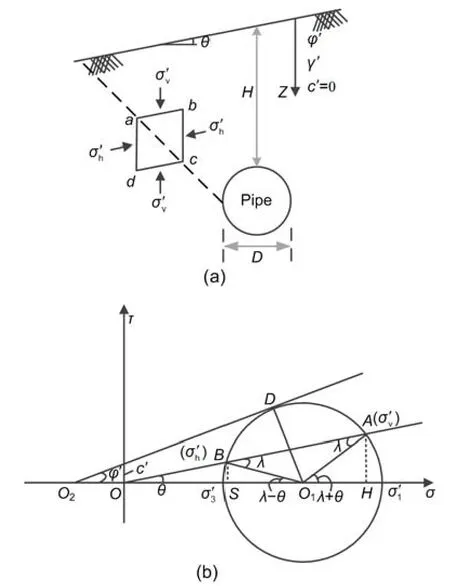
Fig.1 Stress characteristics for soil around a pipeline in inclined ground
Recent experimental evidence revealed that the vertical slip-surface model was only approximate for uplift in loose sand at mediumH/Dratios (Wang et al.,2012).For uplift in medium to dense sands,the failure mechanism is similar to that of the inclined slip surfaces model (Cheuk et al.,2008;Huang et al.,2015).The two symmetrical slip surfaces originate from the pipe waist with an inclination angleβto the vertical.Meyerhof and Adams (1968) stated thatβvaried betweenφ′/4 andφ′/2 for circular footings.Vermeer and Sutjiadi (1985) proposed thatβwas the same as the soil friction angleφ′.Chen et al.(2000) thought the failure angle was consistent with the Mohr-Coulomb failure criterion,and was equal to 45°−φ′/2.White et al.(2001) observed from centrifuge tests thatβwas the dilation angle of sand.
It is clear that there are three problems with the existing methods for estimating the peak uplift resistance:(1) during pipe uplifting,the soil adjacent to the pipe is not in the at-rest condition,therefore,K0,the at-rest soil pressure parameter,is not suitable as the lateral earth pressure ratio;(2) there is paradox in the assumption of vertical slip model;(3) there are different understandings of the inclination angleβfor the inclined slip surfaces model.The most common way of identifyingβin recent research has been to use the particle image velocimetry (PIV) technique (Cheuk et al.,2008;Huang et al.,2015).However,βpredicted by formulas do not match the test results well,and this discrepancy is wider for pipelines buried in the inclined ground.
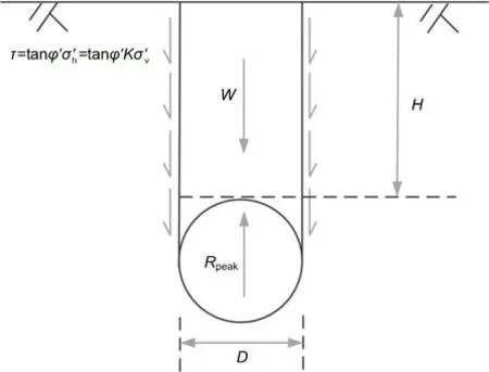
Fig.2 Vertical slip-surface model
3.2 Analysis of the failure angle for a pipe uplifted in inclined ground
To build the numerical model,some assumptions were made:(1) the sliding block bounded by a pair of slip surfaces satisfied the sliding block theory;(2) soil within the slip surfaces transformed from the“at-rest”stress condition to the active limit equilibrium stress condition;(3) the two slip surfaces,originating from the pipe waist,were inclined at angles ofαandβto the verticalon the right and left sides,respectively;(4)the soil satisfied the Rankine earth pressure theory and the Mohr-Coulomb failure criterion;(5) the lateral force on the pipe was not considered;(6) the contact friction between the smooth pipe and surrounding soil was negligible.The uplift resistance consists of the lifted soil wedge and the vertical component of shearing resistance along the two slip planes (Fig.3).
3.2.1 Friction on the slip surfaces
A prism-shaped elementadm(Fig.4) is taken by slicing the soil element in Fig.1 along lineamparallel to the hypothetical failure plane,and along linesadanddc(corresponding to planesadanddmin Fig.4,respectively).The normal stress and shear stress on planeamare denoted asσβ′andτβ′,respectively.lam,ldm,andladare the corresponding side lengths.Therefore,
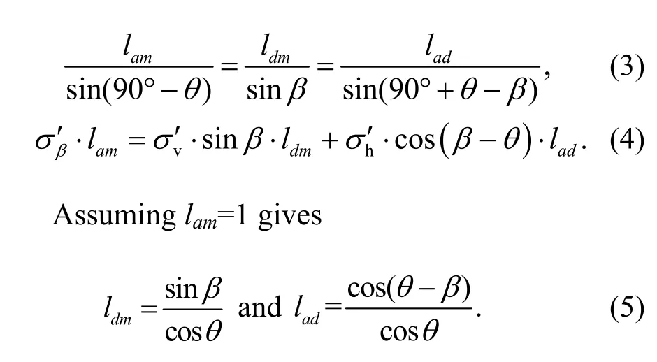
Substituting Eqs.(5),(1),and (2) into Eq.(4)gives
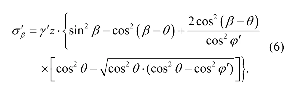
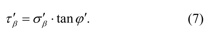
According to the Mohr-Coulomb failure criterion for cohesionless soil,σβ′andτβ′ should satisfy the relationship:
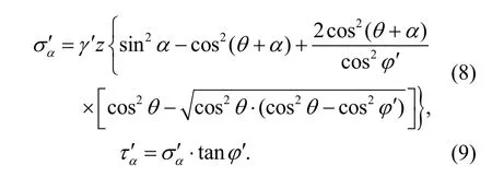
Similarly,the stressesσα′ andτα′ acting on the right failure plane are given as
By integrating the normal stress and the shear stress along both slip planes,the normal force and the shear force can be calculated as
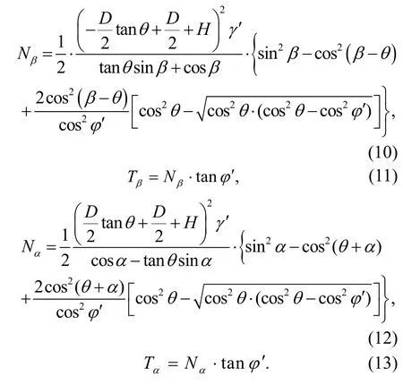
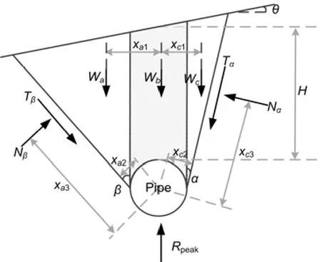
Fig.3 Mechanical condition of a buried pipe for the inclined ground condition
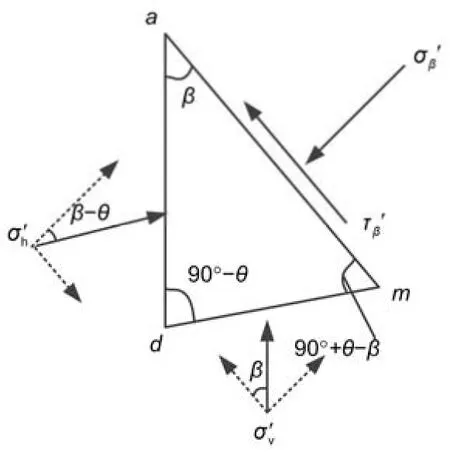
Fig.4 Stress state of the soil element on the left failure plane
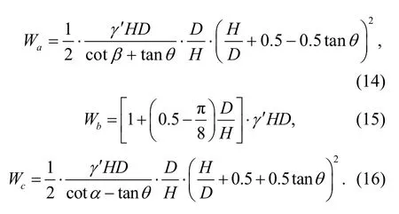
3.2.2 Self-weight of soil between the two slip planes
The uplifted soil block between the two slip planes can be divided into three components with self-weight per unit length ofWa,Wb,andWc,respectively (Fig.3).
3.2.3 Failure plane angles and the peak uplift resistance
The stress condition around the pipeline at the critical state is illustrated in Fig.3.The forces act on the sliding block are the weight of the soil,Wa+Wb+Wc,the normal forces,NβandNα,and the shear forces,TβandTα.All the forces mentioned above should satisfy the balance of force and moment,that is,as
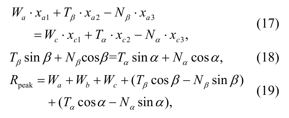
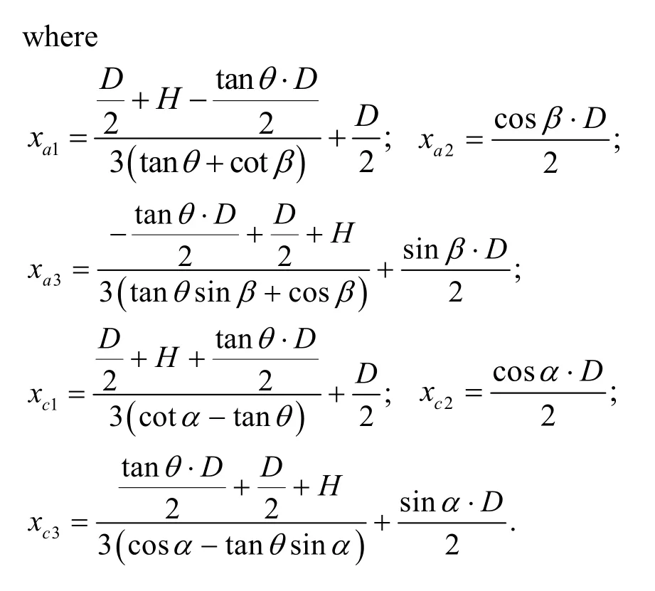
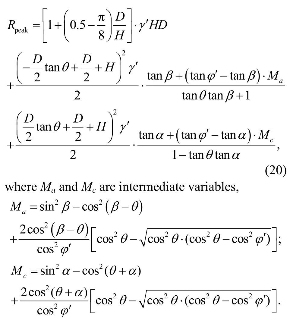
Substituting Eqs.(10)–(16) into Eq.(19),the expression for peak soil resistance is
When the inclination angle of the ground surfaceθis equal to zero,the slip surfaces on the left and right are symmetrical andβ=α.Eq.(19) transfers to:
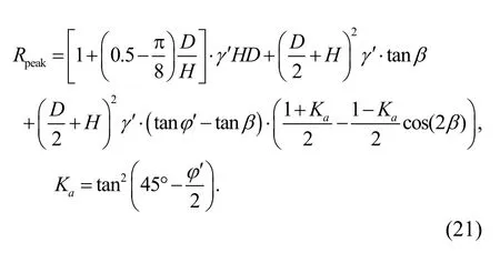
According to Eqs.(20) and (21),the peak uplift resistance is a function of the failure plane anglesαandβ,the ground inclination angleθ,the effective unit weightγ′,the peak internal friction angleφ′,and the embedment ratioH/D.Combining Eq.(17) with Eq.(18) yields Eq.(22),which is given at the end of the page.
In Eq.(22),αandβare the functions of ground inclination angleθ,the peak internal friction angleφ′,and the embedment ratioH/D.Eq.(22) is a transcendental equation,as the analytical solution is difficult to obtain.
4 Slip surface angles
4.1 Inclination angle of the slip surface for the horizontal ground condition
Eq.(22) cannot directly solve the problem of the horizontal ground surface condition whereθ=0° andα=β.To predictαandβin the horizontal ground condition,θis simplified as 0.1°.Fig.5 shows the impact ofφ′ andH/Don the inclination angles of the slip surfaces.AsH/Dincreases from 0.1 to 8,there is a significant increase in the failure angle.This is because the lateral constraint pressure increases with the increasingH/D.Therefore,soil could dilate more easily at a shallower depth,resulting in a steeper slip surface,as observed by Cheuk et al.(2008) and Huang et al.(2015).The failure angle increases asφ′decreases.For a givenφ′,the curves gradually approach the value of 45°−φ′/2 withH/Dfurther increasing from 8 to 80,which confirms the Rankine earth pressure theory and the Mohr-Coulomb failure criterion.
Fig.5 Failure angles of the slip surface versus the embedment ratio H/D for the horizontal ground condition
4.2 Inclination angle of the slip surface for the inclined ground condition
Under the inclined ground condition,Fig.6 shows the impact ofθandH/Don the failure angles with a constant soil internal friction angleφ′ of 35°based on Eq.(22).αon the uphill side is depicted by dashed lines,andβon the downhill side by solid lines.The two slip surfaces are no longer symmetric andαis not equal toβ.αbecomes smaller andβbecomes larger asθincreases.The two slip surfaces rotate towards the downhill direction (Fig.7),and the variation ofβis larger than that ofα.Comparing with the horizontal ground condition,at any specific embedment ratioH/D,the change inαandβincreases asθincreases (Fig.6).WhenH/Dis 0.1,αgradually approaches 0 with the increasingθto the upper bound value of about 23°;for the embedment ratioH/D=2,the upper boundθin Eq.(22) is about 33°.The variation ofαandβwithH/Dis further depicted in Fig.8.Forθ=20°,αandβare significantly impacted by the embedment ratio whenH/D<4;however,H/Dhas a negligible effect onαandβwhenH/Dincreases from 4 to 8,and the curve ofαforθ=20° gradually coincides with that forθ=0.1°.The difference betweenαandβdecreases with the growingH/D.At higher embedment ratios likeH/D=8,the effect of the ground surface inclination is negligible and the two slip planes during pipeline uplifting can be simplified as symmetric.
Due to the existence of initial shear stress,an underground structure buried in inclined ground is subjected to a horizontal force (Zhu and Randolph,2010),especially when the ground inclination is close to the soil friction angleφ′.The failure angles ofβfor the variation ofθwhenH/D=20 are plotted in Fig.9.There is a significant increase in the gradient of the curves whenθis approximately equal toφ′−10°.When the slope angleθapproaches the soil friction angleφ′,the slope is prone to be unstable;therefore,the pipe under the slope is subject to an increasing downslide force.The horizontal force component of the downslide force is no longer negligible,which contradicts the assumption that the horizontal force on the pipe is negligible.Thus,all the analysis above,derived using the proposed analytical formula,is applicable for the condition thatθ<φ′−10°.
Fig.6 Failure angles of the slip surface versus the ground inclination θ (φ′=35°)
Fig.7 Uplift failure mechanism for the inclined ground condition
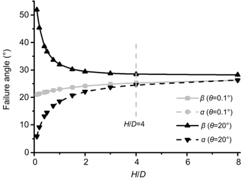
Fig.8 Failure angles of the slip surface versus the embedment ratio H/D for the inclined ground condition
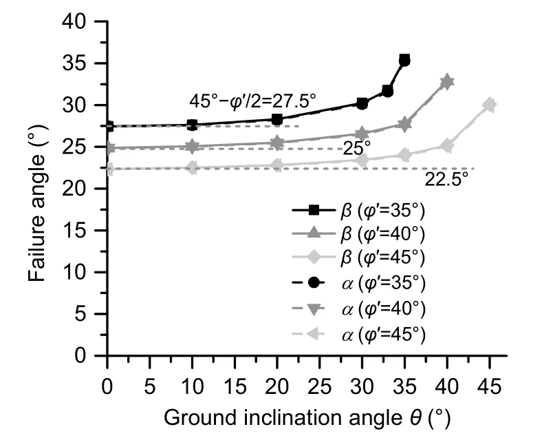
Fig.9 Failure angles of the slip surface at H/D=20 for the inclined ground condition
4.3 Design chart for slip surface angles
Fig.10 reveals the variation of failure angles withH/Dandθunder internal friction anglesφ′of 35°,40°,and 45°,respectively.Based on the analysis,failure angles are influenced byφ′,θ,andH/D,particularly for shallow burial conditions.There is a slight decrease inαandβwith the increasingφ′.Compared with the horizontal ground condition,the impact of ground inclination on failure angles decreases with the increasingH/D.Prediction of peak uplift resistance using Eq.(20) requires knowledge of bothαandβ.Therefore,Fig.10 provides a direct engineering reference for designers.
5 Peak soil resistance
The peak uplift resistance of a buried pipe in horizontal ground has historically been expressed in the normalized form as (DNV,2007)
wherefdis the uplift resistance factor,which depends on soil properties and slip surface modes (vertical and inclined).Proper estimation of the uplift resistance factorfdfor pipeline design is important in preventing the upheaval buckling and reducing the investment.Many aspects regarding this factor have been discussed,including soil classification and soil density(Trautmann et al.,1985;DNV,2007).
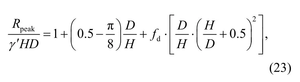
For the inclined ground condition,the peak uplift resistance expressed in Eq.(20) is normalized byγ′HDfrom both sides of the equation.The normalized formRpeak/(γ′HD) can also be expressed by Eq.(23).To distinguish the inclined ground condition from the horizontal ground condition,the dimensionless uplift resistance factorfdis replaced byfd′ as
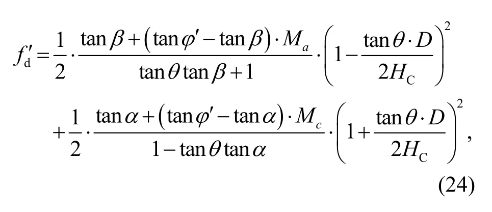
whereHC=H+0.5Dis the buried depth to the centre of the pipe.The factorfd′ is a function ofφ′,H/D,θ,and the failure plane anglesαandβ.
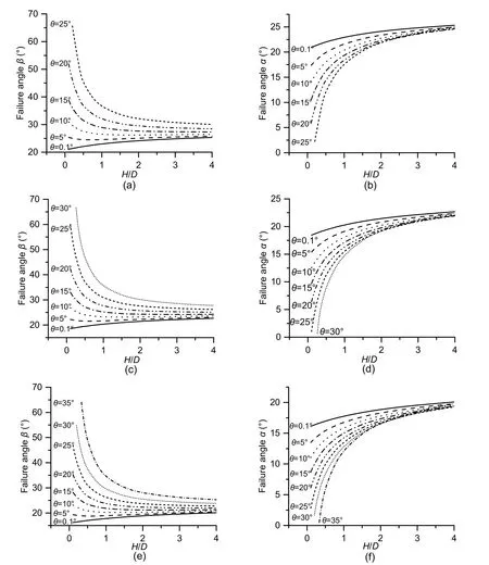
Fig.10 Design chart for the failure angles
Based on the above analysis of the slip surface angles and Eq.(24),the normalized formfd' versusθis plotted in Fig.11 (p.378).ForH/D=1,fd′ is almost constant at 0.53 with the variation ofθfrom 0.1° to 25°,despite the difference of failure angles.However,fd' decreases significantly with the increasingθwhenH/D=0.5,especially whenθis between 15° and 25°.Fig.12 (p.378) shows the relationship betweenfd' (fd)andH/Dunder various ground inclinationsθ.For a specificθ,fd' first increases significantly with the increasingH/DwhenH/Dis less than 1,then gradually reaches a constant value whenH/Dis larger than 4.This is because the impact ofθonαandβis negligible whenH/D≥4 (Fig.8).According to Fig.12,there is no significant difference betweenfd′ andfdwhenH/D≥1.The calculatedfd' in this study is close to the results of Vermeer and Sutjiadi (1985) and between the upper and lower bounds of the DNV method.ForH/D<1,fd′ decreases significantly with the increasingθ.Whenθ≥15°,fd' under shallow burial conditions (e.g.H/D<0.5) is smaller than the lower bound value recommended by DNV (2007),resulting in an inadequate uplift resistance and the potential for upheaval buckling.Therefore,sufficient burial depth is essential during the pipeline installation,especially for the inclined ground condition.However,burial depth is one of the main sources of installation cost and is largely limited by the budget.Inadequate burial depth is one of the reasons why the upheaval buckling phenomenon generally occurs in sloping regions.
The present design codes for petroleum and natural gas pipelines do not consider the influence of ground inclination on peak uplift resistance.For some regulations (e.g.ISO (2017) and DEP 31.40.00.10),the minimum pipeline embedment depth is 0.5 m.Pipelines for oil and gas transportation normally have a diameter of 1–2 m,and the corresponding minimum burial ratioH/Dis less than 0.5.According to Figs.11 and 12,the safety factor decreases due to the ground inclination under this“very shallow”burial condition.To illustrate the impact of ground inclination on peak uplift resistance under the shallow burial condition(H/D<1),a reduction factorkincline=fd′/fdis introduced as
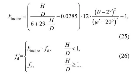
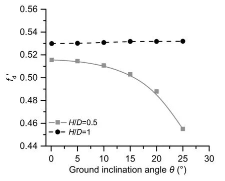
Fig.11 fd' versus θ (φ′=35°)
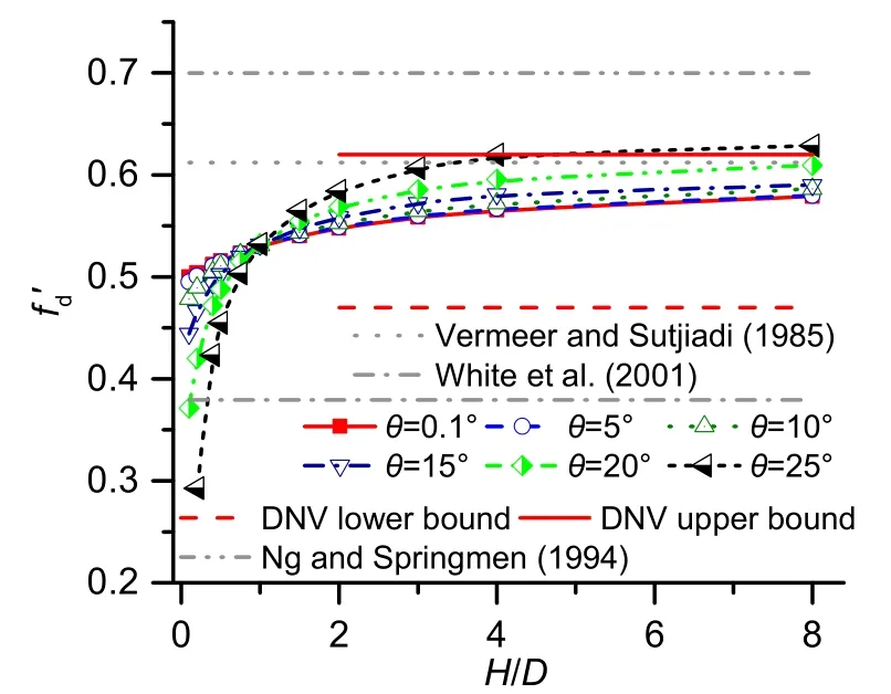
Fig.12 fd' versus H/D (φ′=35°)
Calculating the value offd' by Eqs.(25) and (26),then replacingfdwithfd' in Eq.(23),the peak uplift resistance of a pipe buried in the inclined ground condition can be predicted.
6 Experimental validation
Centrifuge modelling has been widely adopted to study soil-structure interactions due to the high cost and labour associated with full-scale tests.These centrifuge tests use the scaled models and increase the body stresses by centrifugal acceleration.The experiments presented here were carried out at an acceleration level of 30g,wheregis the gravitational acceleration,using the ZJU-400 centrifuge at Zhejiang University,China (Chen et al.,2010).The model pipe was made from a hollow aluminum tube with an external diameter,D,of 40 mm and wall thickness of 2 mm.The material used in the tests was classified as poorly graded sand.The diameters of the sand particles at which 10%,30%,and 60% by mass are finer were 0.11,0.14,and 0.19 mm,respectively.Medium dense samples with the targeted relative density,ID,of 60% were prepared by dry pluviation.Shear tests on eight specimens revealed that the sand had a peak state friction angle of around 42°.The tests were divided into three series with the ground sloping,θ,of 0°,10°,and 20°,respectively.The depth of the pipe crown,H,varied between 0.5Dand 4Dto simulate the shallowly buried pipelines.Digital images were captured and PIV technique was used to track the soil movement.Details of the experiment were described by Liu (2017).
Fig.13 shows the variation of tested failure angles withH/D.With the increasingH/D,βdeclines andαrises,showing the decreasing impact of ground inclination on the rotation of the two failure planes,as depicted in Figs.8 and 10.Under the sameH/D,βincreases andαdecreases with a higherθ.Although the experimentalβis relatively higher andαis smaller than the corresponding analytical prediction,the difference ofRpeak/(γ′HD) between the analytical and experimental results is within 6% (Fig.14).Therefore,the upheaval buckling problem of a shallow buried pipeline in inclined cohesionless soil can be well-predicted according to the proposed analytical method.
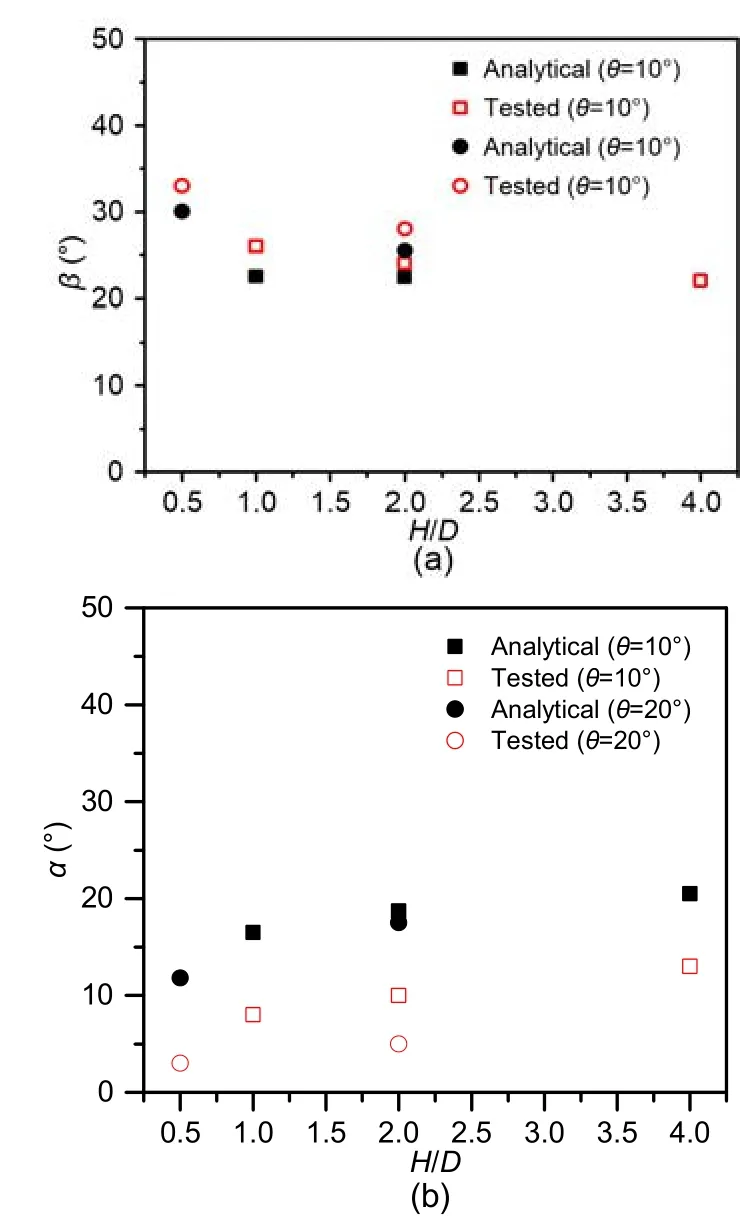
Fig.13 Comparison of failure angles of β (a) and α (b)
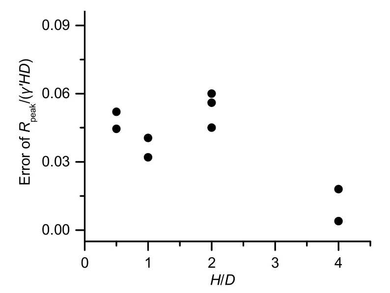
Fig.14 ComparisonofRpeak/(γ′HD)between analytical and experimental results
7 Conclusions
The upheaval buckling problem of shallow buried pipelines in inclined cohesionless soil was studied analytically.According to the Rankine earth pressure theory and Mohr-Coulomb failure criterion,the failure angles for an uplifted pipe were discussed in detail.An equation for predicting the peak uplift resistance of a buried pipe under an inclined ground condition was proposed and its simplified form was presented for the designers.Finally,the analytical method was validated by centrifuge experiments.Based on the analysis,the following conclusions were reached:
The inclinations of failure plane angles are not the same for the inclined ground condition.The two failure planes rotate in the downhill direction.The area of soil bounded by two slip surfaces for inclined ground is larger than that in horizontal ground.The magnitude of rotation increases with the increasing ground inclinationθfor a given embedment ratioH/D,and decreases with the increasingH/Dfor a givenθ.WhenH/Dis larger than 4,the influence of the ground slope is negligible.
The peak uplift resistance reduces in inclined ground,especially whenH/Dis less than 1.The relevant design codes do not consider the impact of ground inclination on the uplift resistance,resulting in a decrease in the safety factor.
Contributors
Bo HUANG and Dao-sheng LING designed the research.Jing-wen LIU and Ji-ying FAN did the theoretical derivation and wrote the first draft of the manuscript.Bo HUANG and Ji-ying FAN helped to organize the manuscript,and revised and edited the final version.
Conflict of interest
Bo HUANG,Jing-wen LIU,Ji-ying FAN,and Dao-sheng LING declare that they have no conflict of interest.
Appendix A:derivation of σh′
The stress acting on planead(σh′) is equal to the length ofOB,that islOB(Fig.1).The coordinates of pointAare
Based on the geometrical relationship in Fig.1b,
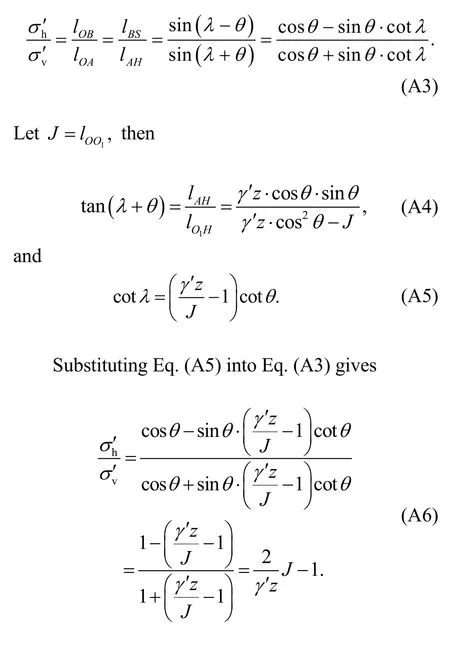
At the limit equilibrium state,the Mohr circle is tangential to the Mohr-Coulomb yield envelopeO2Dat pointDas shown in Fig.1b.Therefore,
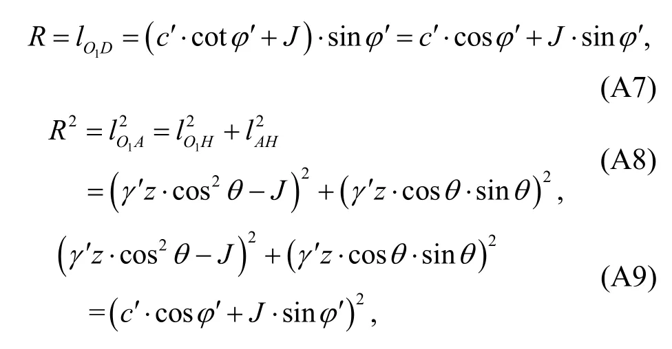
whereRis the radius of the Mohr circle.For the cohesionless soil,c′=0,Jcan be simplified as
Bransby MF,Brunning P,Newson TA,et al.,2001.Numerical and centrifuge modelling of the upheaval resistance of buried pipelines.Proceedings of the 20th International Conference on Offshore Mechanics and Arctic Engineering.
 Journal of Zhejiang University-Science A(Applied Physics & Engineering)2021年5期
- Journal of Zhejiang University-Science A(Applied Physics & Engineering)的其它文章
- Tunable patterning of microscale particles using a surface acoustic wave device with slanted-finger interdigital transducers*
- Influences of fiber length and water film thickness on fresh properties of basalt fiber-reinforced mortar*
- Multi-geomagnetic-component assisted localization algorithm for hypersonic vehicles*
- Framework of automated value stream mapping for lean production under the Industry 4.0 paradigm*
- Optimization of smoke exhaust efficiency under a lateral central exhaust ventilation mode in an extra-wide immersed tunnel*