
Analytical solutions to ground settlement induced by ground loss and construction loadings during curved shield tunneling*
2021-04-15 00:11ShaohuaLIMingjuZHANGPengfeiLI
Shao-hua LI, Ming-ju ZHANG, Peng-fei LI
Analytical solutions to ground settlement induced by ground loss and construction loadings during curved shield tunneling*
Shao-hua LI1,2, Ming-ju ZHANG1, Peng-fei LI†‡1
Key Laboratory of Urban Security and Disaster Engineering of the Ministry of Education, Beijing University of Technology, Beijing 100124, China China Railway 15th Bureau Group Co., Ltd., Shanghai 200070, China †E-mail: lpf@bjut.edu.cn
This paper focuses on the ground settlement induced by the construction of a curved shield tunnel. Ground loss and construction loadings are the two factors causing ground settlement, and two corresponding analytical models were developed. First, the ground settlement due to ground loss was analyzed based on 3D image theory. The “integrative gap at shield tail” (IGST) and overcutting gap of a curved tunnel were considered. Second, the ground settlement due to construction loadings was analyzed by modifying Mindlin’s solutions. The additional thrust, frictional force, and grouting pressure were considered. Subsequently, a case study and a parameter analysis were conducted. Finally, the obtained solutions were compared with a classical analytical solution, numerical simulations, and monitored results. The proposed model could effectively predict the ground settlement induced during curved shield tunneling.
Curved tunnel; Image theory; Mindlin’s solution; Ground loss; Ground settlement
1 Introduction
The design of metro routes should conform to the principles and requirements of metro vehicle running safety, economic benefits of metro operation, project implementation safety, and environmental protection (Li W et al., 2019). Straight tunnels are desirable, but curved tunnels, including some with a small radius, cannot be avoided in metro lines because of restricted site conditions, buildings, and other factors (Zhang et al., 2020). With the widespread application of compound shields in new metro lines, the construction of curved tunnels is increasing. Constructing a curved shield tunnel is unlike constructing a straight tunnel, and its implementation depends mainly on the following technological measures: (a) use of shield hinge equipment; (b) use of a copy cutter (an over cutter); (c) control of hydraulic jacks; (d) use of wedge-shaped segments. In many cases, the above measures may aggravate the disturbance of the strata during shield tunnel construction, which may damage adjacent underground pipelines and buildings (Li SH et al., 2020). Most theoretical studies on the influence of shield excavation on ground settlement have focused on straight tunnels; studies on curved shield tunnels have been limited primarily to numerical simulations and field monitoring (Kasper and Meschke, 2006; Sugimoto et al., 2007; Alsahly et al., 2016; Lu et al., 2018).
Construction loadings and ground loss have been investigated by many researchers as the key factors influencing shield tunneling, causing ground displacement during construction (Wongsaroj et al., 2005; Migliazza et al., 2009; Wei et al., 2012; Li PF et al., 2019a, 2019b, 2020). Ground loss has the most significant impact on ground displacement both in the transverse direction (Peck, 1969; Mair et al., 1993) and in the longitudinal direction (Attewell and Woodman, 1982; Sagaseta, 1987). Engineering practice shows that ground loss will first manifest along the tunnel axis, i.e. in the direction of shield excavation; subsequently, ground loss on both sides of the excavated tunnel and along the tunnel axis overlaps (Attewell et al., 1987). In a conventional 2D context, tunnel transverse theory has been applied; however, this theory cannot solve the problem of ground settlements along the tunnel axis. Along the direction of shield excavation, the location of ground loss during shield tunneling is concentrated mainly at the excavation face and shield tail. The analytical solutions to the longitudinal and transverse ground settlements due to ground loss under plane and 3D conditions have been derived using image theory (Sagaseta, 1987). A gap parameter was defined to give a comprehensive estimate of the ground loss induced by shield tunneling. Its calculation process has been reported in detail (Lo et al., 1984; Ng et al., 1986; Lee et al., 1992), providing guidance for follow-up plane analytic theories (Verruijt and Booker, 1996; Loganathan and Poulos, 1998; Wei et al., 2013; Kong et al., 2019; Lu et al., 2019). However, the plane ground loss proposed in the above theory is based on the assumption that the ground loss is evenly distributed along the axis of a straight-line tunnel. This approach is inapplicable to curved tunnels with an asymmetric distribution of the ground loss along the tunnel axis. Despite recent developments (Wei et al., 2012; Zhang and Huang, 2014), 3D theoretical research has not yet been applied to curved tunneling.
During shield construction, the main loads acting on the soil are the additional thrust and torque on the front of the cutterhead, frictional force between the shield skin and the soil, and additional grouting pressure at the shield tail (Tang et al., 2010; Wei et al., 2012). Many studies (Tang et al., 2010; Zhu et al., 2014; Liang et al., 2015; Jiang et al., 2018; Zhang et al., 2018) on the ground displacement induced by these construction loadings have been conducted using Mindlin’s solutions (Mindlin, 1936). However, most of these studies were on straight-line tunnels. The loading area in the above calculation models is a simple geometric shape, such as a flat surface or a cylinder. The Mindlin formulae can directly be applied to these solutions after coordinate transformation. However, this simple approach is unsuitable when the loading area is a complex spatial surface, as in the model of a curved tunnel.
Thus, in this study, we established theoretical formulae for ground settlements due to ground loss and construction loadings during curved shield tunneling. Based on image theory applied to ground settlements induced by any unit void displacement in a semi-infinite body, the settlements due to ground loss at the shield tail and excavation face were calculated by integrating over the actual 3D spatial region. In terms of construction loadings, Mindlin’s solutions were modified to give universal solutions, which enabled the construction of theoretical formulae for the ground displacement induced by the force acting on the space surface per unit area. Finally, the ground settlements due to assorted loadings during the construction of curved shield tunnels were deduced and calculated.
2 Proposed model
2.1 Problem description
Due to the disturbance of strata during shield tunneling construction, ground settlements are a major concern. Ground settlements can be induced mainly by two factors: ground loss, which is usually the principal reason, and construction loadings, e.g. additional thrust, frictional force, and additional grouting pressure during the excavation of the shield tunnel.
2.1.1 Ground settlement induced by ground loss
To analyze the ground settlement induced by ground loss during shield construction, complex 3D ground loss was generalized to an equivalent ground loss parameterin the plane model (Lee et al., 1992):

wherepis the physical gap at the shield tail when grouting is not considered.pis equal to the gap between the segment and the soil after the segment emerges from the shield tail, i.e.p=2+′, wheredenotes the shield thickness and′ denotes the clearance required for segment erection. When the grouting effect is considered,pshould be appropriately reduced (Chi et al., 2001).3D*is the equivalent 3D elastoplastic displacement at the excavation face, andis the clearance parameter with yawing excavation as the main factor.
Earth pressure balance at the excavation face is assumed during tunneling; in this case,3D*=0. There is no yaw excavation in straight-line shield tunneling (=0) (Fig. 1). The overburden height () is measured from the tunnel axis. The tunnel advances forward along theaxis from the point (−, 0,) to the icon position (0, 0,), whereis the tunneling length. An annular gap (p) is formed after the segments emerge from the shield tail during stepwise excavation. The tail gap can be defined as the volume between two cylinders with the same length (i.e. the tunneling length) and different radii (the outer diameterof the shield tunneling machine and outer diameterof the segmental lining). This gap is the main cause of ground displacement. It can be solved by the integral of the ground displacement (Sagaseta, 1987) generated by a void of unit volume over this spatial volume region (Zhang and Huang, 2014).
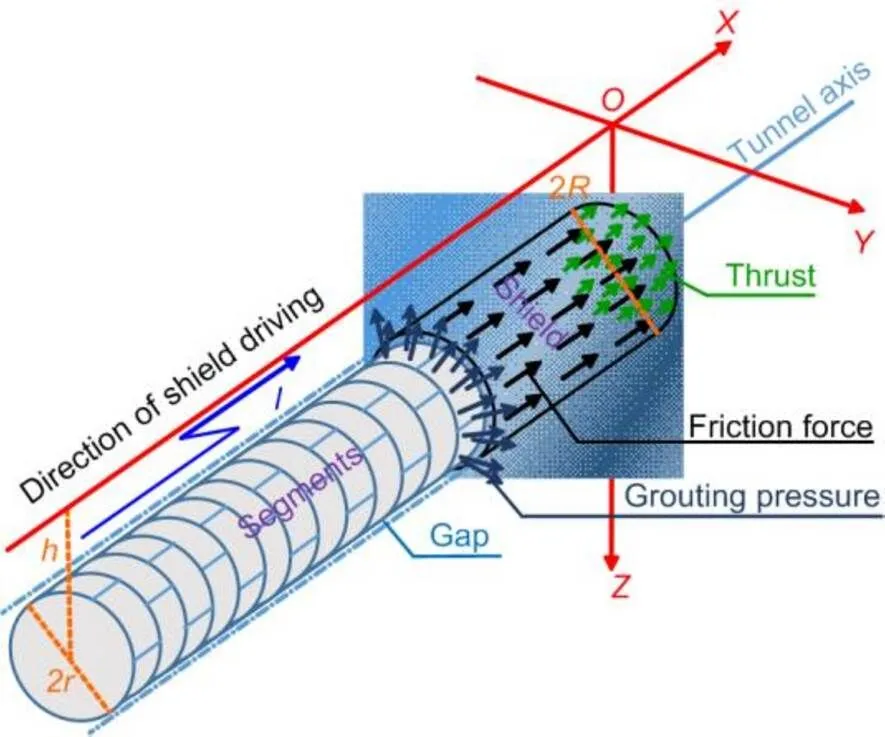
Fig. 1 Straight-line shield tunneling and soil mechanical model
2.1.2 Ground settlement induced by construction loadings
The construction loadings causing ground displacement in shield construction include the additional thrust on the front of the cutterhead, frictional force between the shield skin and the surrounding soil, and grouting pressure at the shield tail (Fig. 1). Here, the torque acting on the front of the cutterhead is neglected because it has little effect (Tang et al., 2010). To analyze the influences of the above factors on ground settlement, two typical steps were used in this study. First, the coordinates of the load point (microelement) in the cylindrical coordinate system are converted to the equivalent coordinates of the Mindlin formulae for substituting in the Cartesian coordinate system. Second, the ground displacement is obtained by integrating the cylindrical coordinate system (Mindlin, 1936; Tang et al., 2010; Zhu et al., 2014). Note that the grouting pressure should be decomposed into horizontal and vertical components parallel to the coordinate axes in advance.
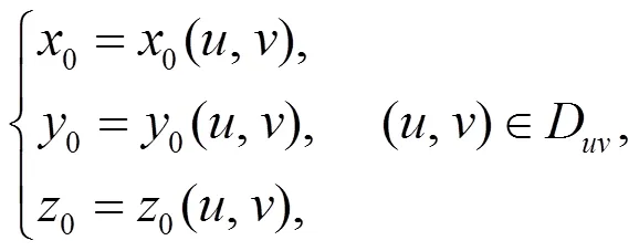
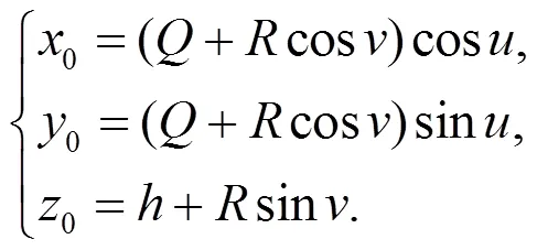
The ground displacement due to straight-line tunnel construction can be analyzed based on a cylindrical model (Fig. 1). In comparison, for a curved tunnel, the axis is composed of a section of broken lines. For the convenience of analysis, the axis is considered a circular arc (with a curvature radius of). The advancing trajectories of the shield machine and the appearance of segmental linings are along the standard spatial torus (Fig. 2). To characterize the nonuniform radial soil movement model adopted in this study (Lee et al., 1992; González and Sagaseta, 2001; Pinto and Whittle, 2014), the displacement parameteruof the vertical movement of the tunnel segments is introduced (u=0 in Fig. 2). Taking (0,0,0) as the coordinates of an arbitrary point at the standard torus, we can write the space equations of the outer surfaces of the shield and segments, respectively, as follows:
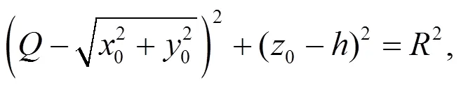
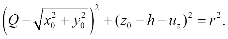
The tunnel advances forward along the tunnel axis from the point (cos,sin,) to the icon position (0,,), and=π/2−/at the starting point in Fig. 2 (the shield tunneling direction is clockwise when viewed from above). The tail gap can be determined as the volume between two tori with the same arc (i.e. tunneling length) and different radii (the outer diameterof the shield tunneling machine and the outer diameterof the segmental lining). The integral of the ground displacement (Sagaseta, 1987) generated by a void of unit volume over this complex spatial volume region is taken to determine the ground displacement due to this part of the ground loss.
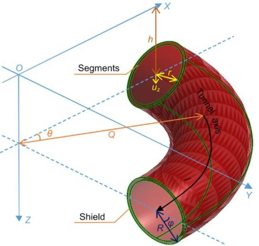
Fig. 2 Curved shield tunneling model
The action mode of the additional thrust on the excavation face is the same as that observed in a straight-line tunnel. Therefore, the influence of additional thrust in the curved tunnel can be solved using the existing method (Mindlin, 1936). Note that the surface on which the frictional force or grouting pressure acts changes from a cylindrical surface in a straight-line tunnel to a spatial torus in a curved tunnel, bringing spatial complexity in the load direction. Therefore, more components need to be derived for a curved tunnel than for a straight-line tunnel when these spatial forces are decomposed along the coordinate axis.
2.2 Analytical solutions to ground settlement induced by ground loss
During the excavation of a curved shield tunnel, there is a nonuniform gap between the outer wall of the segmental lining and the boundary soil layer. The boundary soil converges radially toward the center of the tunnel and comes into close contact with the segment outer wall. The important factor that needs to be addressed here is the surrounding ground displacement induced by the “gap” (ground loss) formed by the shield tunnel excavation.
The gap is assumed to be composed of multiple microgaps. If the ground displacement due to a microgap can be obtained, the above problem can be solved by integrating this value over the gap volume region. Sagaseta (1987) proposed the use of image theory to solve the problems of displacement and stress due to a “point sink” in a linear elastic semi-infinite medium. This study focuses on a solution of the ground settlement, introduced in the following three steps:
1. For a spherical microgap (“point sink”) with a unit radius of 1 at(0,0,0) in a Cartesian coordinate system (Fig. 3), the ground settlement (displacement in the positive direction of theaxis) induced by the sink at an arbitrary point(,,) can be expressed as
2. The ground settlement produced at(,,) due to the volume expansion (negative sink) of the same size at the image position point′(0,0,−0) can be expressed as
where
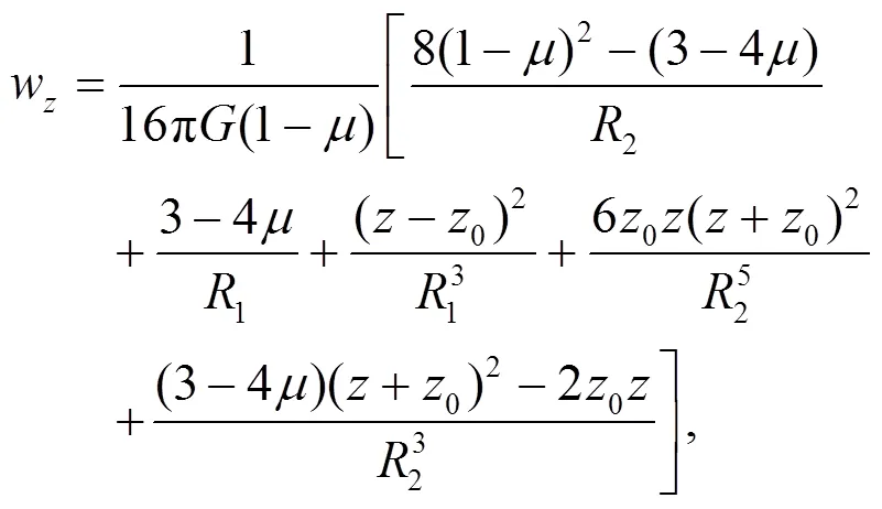
3. Eqs. (4) and (5) are derived under the condition of an infinite medium, which can be used to calculate the ground settlement due to a point sink and negative sink, respectively. To be consistent with the conditions of the actual soil boundary (a semi-infinite medium), the additional shear stress generated in the first two steps at the ground surface ought to be exerted on the same position in the opposite direction, which will lead to ground settlement, i.e. by solving:
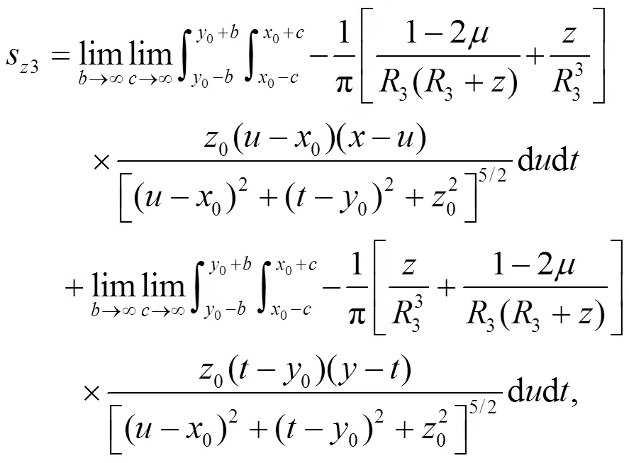
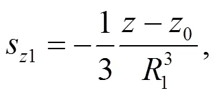
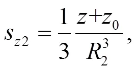
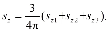
From the above three steps, the ground settlement at an arbitrary point(,,)due to a gap with a unit volume of 1 at(0,0,0) in the realistic condition of a semi-infinite medium can be obtained as
The 3D image theory model is applicable not only to the case of a symmetrical distribution of ground loss around a straight-line tunnel (Zhang and Huang, 2014), but also to cases of an asymmetric distribution of ground loss along a certain curve or within a certain region. A curved tunnel exhibits a unique 3D characteristic during shield tunneling (Fig. 2). The point on the outer wall of the shield machine (or segment) (0,0,0) is (cos,sin,0), whererepresents the variable curvature radius. In the nonuniform radial ground loss mode, the ground settlement induced by the ground loss between the outer wall of the shield machine and the outer wall of the segment can be expressed as
Given synchronous grouting while tunneling, the gappbetween the segment and the soil will be partially filled by a grouting slurry in time, which equivalently gives rise to a “negative” gap at the shield tail. The “integrative gap at shield tail” (IGST) parametertis introduced in this study to reflect the integrative influence of these two parts of the gap (see Fig. 4, andu=t/2 in the model of the nonuniform ground loss). Herein,t=p, whereis a correction coefficient, which can be determined depending on the actual grouting condition or using the method proposed by Chi et al. (2001).
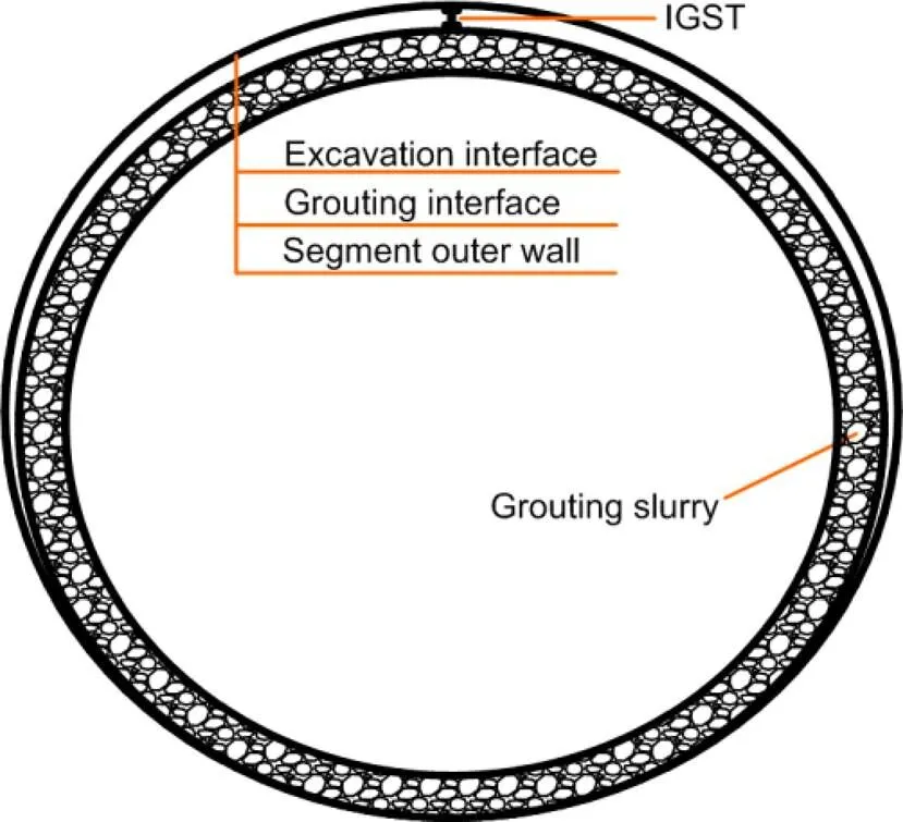
Fig. 4 Integrative gap at shield tail (IGST)
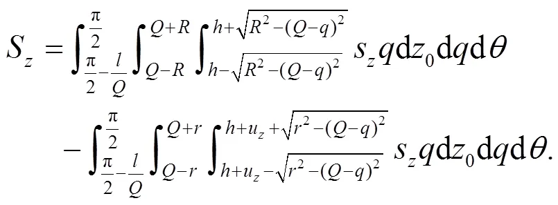
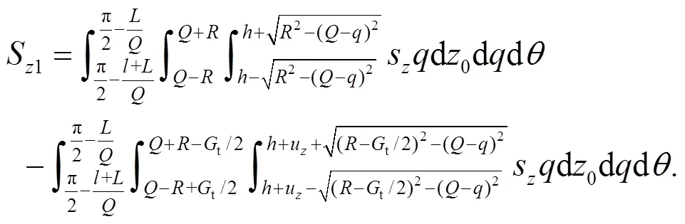
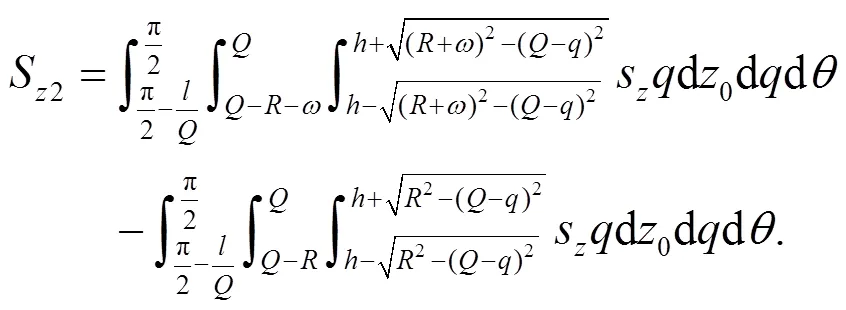
When the center of the excavation face arrives at the point (0,,) (Fig. 2), the range of the tori representing the actual ground loss at the shield tail along the tunnel axis direction is from0=−−to0=−, whereis the length of the shield machine, and0indicates that the point position moves clockwise a distance of arc length |0| from point (0,,) along the tunnel axis. For instance,0=−indicates that the distance from point (0,,) to the point (0=−) behind the excavation face (anticlockwise) is. With Eq. (8), the ground settlement induced by the ground loss (t) at the shield tail of a curved shield tunnel can be expressed as
Note that during yawing excavation of a curved shield tunnel, the soil inner side of the curved tunnel at the excavation face will be over-excavated using a copy cutter. Thus, it is necessary to estimate this uneven ground loss on both sides of the curved tunnel at the excavation face (Lu et al., 2018). As shown in Fig. 5,M1andM2are the lengths of the front and rear shield bodies, respectively (Huynh et al., 2016). Considering the influence of shield hinge equipment, we assumed that the theoretical value of the over-excavationais set such that the two segment rings are in the shield, i.e.M1=M2=2(is the width of the segment ring), andacan be estimated as (Sigl and Atzl, 1999)
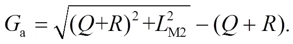
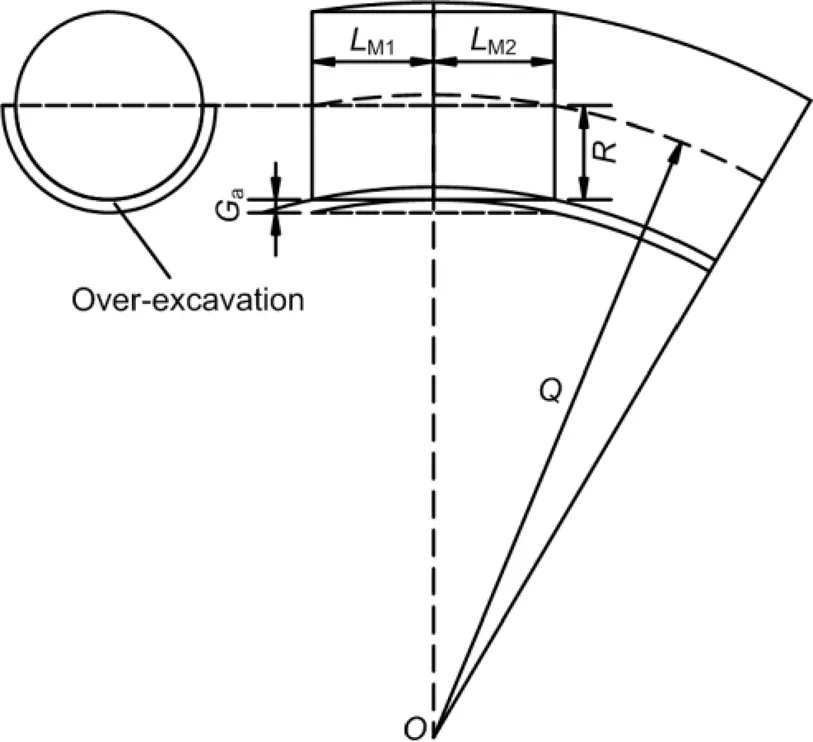
Fig. 5 Over-excavation of a curved tunnel (Festa et al., 2012; Huynh et al., 2016)
At the same time, the soil displacement is constrained in three dimensions because of the prompt support provided by the shield after excavation, andashould be appropriately reduced. The reduction factor is taken as 1/3 (Lo et al., 1984), i.e. the overcutting gap at the excavation facea/3. The ground settlement induced byin the curved tunnel can be expressed as
2.3 Analytical solutions to ground settlement induced by construction loadings
2.3.1 Modification and application of Mindlin’s solutions for a spatial surface
Mindlin (1936) proposed analytical solutions for the displacement at an arbitrary point (,,) when a force(concentrated force) parallel or normal to the boundary is applied at point (0, 0,) in the interior of a semi-infinite elastic solid. In classical models, to estimate the ground displacement induced by construction loadings, the coordinate of the force action is converted to point (0, 0,) in advance for using Mindlin’s solutions. However, this process is cumbersome and error-prone when implemented in the case of the complex spatial position of a force action point. Therefore, a general formula for convenient calculation is proposed in this study by replacing the point (0, 0,) specified in Mindlin’s solutions with an arbitrary point (0,0,0). As a result, for the interior of the semi-infinite elastic solid, we can express the ground settlements due to a unit force acting in the positive directions of the,, andaxes (the coordinate system is the same as those in Figs. 1 and 2) at an arbitrary point (0,0,0) as follows:
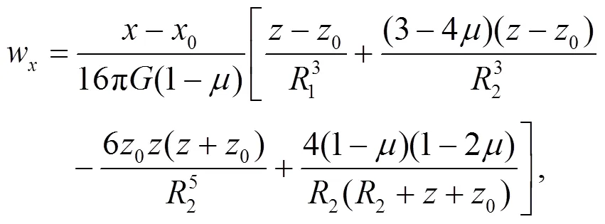
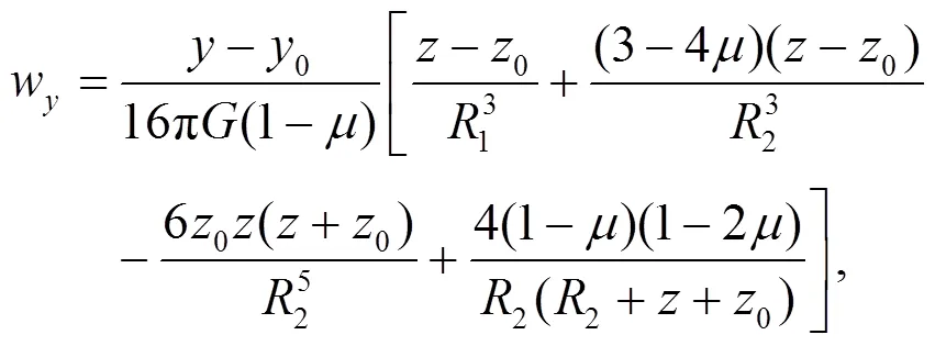
whereis the elastic shear modulus of the soil, and=s(1−20)/(2−2), wheresis the compression modulus of the soil, and0is the static lateral pressure coefficient.
The following statements are based on the rewritten Mindlin’s solutions. Taking the force per unit areafin the positive direction of theaxis as an example, we assume that facts on a spatial surface, which can be expressed by
whereDdenotes the bounded closed region, andis an undetermined function argument.
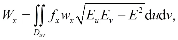
where′0uand′0vdenote the partial derivatives of function0=0(,) with respect toand, respectively, similar to′0u,′0v,′0u, and′0v.
Similarly, the ground settlements due to the forces per unit areafandfacting on a spatial surface in the positive directions of theandaxes are given by
2.3.2 Solutions to ground settlement induced by construction loadings
2.3.2.1 Additional thrust
Note that there should be a negative sign in front of1given that its direction is the negative direction of theaxis in the coordinate system (Fig. 2).
2.3.2.2 Frictional force
The frictional force2is assumed to be distributed nonuniformly along the outer torus of the shield. At the point (,) (Fig. 2)around the shield body,2can be computed using the following expression (Alonso et al., 1984; Liang et al., 2015; Jiang et al., 2018; Zhang et al., 2018):
where
sdenotes the softening coefficient, ranging from 0.83 to 0.97(Zhang et al., 2013),σis the radial normal stress acting on the shield,is the soil unit weight, andis the angle of the skin friction, ranging from 6.5° to 9° (Potyondy, 1961).
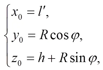
The equation of a spatial torus given by Eq. (2) can also be expressed by the following parametric equation:
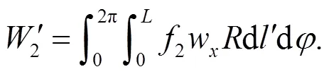
Ultimately,the ground settlement induced by2can be expressed as
2.3.2.3 Grouting pressure


where1is the arc length of the grout, equal toin this study.
Ultimately,the ground settlement induced by3can be expressed as
3 Case study and parameter analysis
As a case study, we selected a shield tunnel with a small curvature radius from a project located between the Wangfuzhuang and Dayangzhuang stations on the Jinan Cityrail transit R1 line (Lu et al., 2018), China. Thick alluvial viscous land layers are widely distributed in this area, and the thickness of quaternary overburden is greater than 50 m. Within the range of 4 m surrounding the tunnel, the soil comprises mainly loess, silty clay, and clay, the cohesiveness and friction angle of which are 40 to 52 kPa, and 20° to 28°, respectively.
The input parameters were set to the following illustrative values:300 m,=21.34 m,=3.34 m,=3.2 m,=1.2 m,=100 m,=8 m,t6 cm,=3.16 mm,1=15 kPa (Tang et al., 2010; Zhu et al., 2014),s=0.88,=7° (Potyondy, 1961),3=0.2 MPa,=0.3, and5.79 MPa.
3.1 Axial ground surface settlement
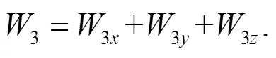
Fig. 6 depicts the ground settlements along the curved tunnel axis when the center of the cutterhead reaches the cross-section0=0 ((0,,) in Fig. 2). In an ideal condition, the ground settlement in the axial direction can also be used to represent the time history curve of the ground surface settlement at section0=0 with the shield advancing.From Fig. 6, the following results can be observed:
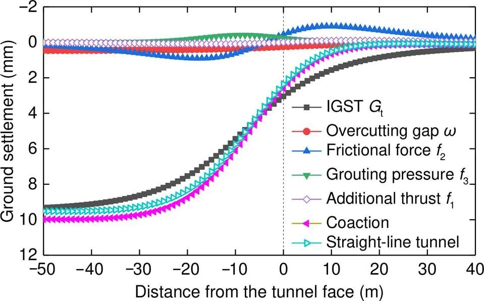
Fig. 6 Ground surface settlements along the tunnel axis under various factors
1. The ground surface settlement induced by IGST accounts for the highest proportion of the total deformation, and the settlement behind the shield tail is large, whereas it decreases gradually in the direction of excavation.
2. The variation in the axial ground settlement induced by the overcutting gap is identical to that induced by the IGST.
3. The additional thrust induces the least ground settlement. Ground uplift appears in front of the excavation face, which is centrosymmetric with the ground settlement behind the excavation face.
4. The ground settlement induced by the frictional force is significant, and its variation along the tunnel axis is very similar to that induced by the additional thrust; the only difference is that the symmetry point changes to the center of the shield. In this case study, the peak ground uplift induced by the frictional force was about 0.9 mm at the section0=10 m.
5. The variation in the axial ground uplift induced bythe grouting pressure is analogous to Gaussian shape. In this case study, the peak ground uplift induced by the grouting pressure was about 0.4 mm at the section0=−8.6 m. Under the coaction of the above five factors, the variation in the axial ground settlement exhibited an “S” shape, and the peak ground settlement was about 9.98 mm at the section0=−46 m.
For acomparative analysis, the ground settlement in the case of a straight-line shield tunnel under the influence of the previous factors (excluding the overcutting gap in the curved tunnel) was determined, and the parameters were set as above. Except for the influence of the overcutting gap, the computational results of the other factors were largely similar to those shown in Fig. 6. This indicates that when shield tunneling in the horizontal plane, the variation in the ground settlement along the tunnel axis induced by construction does not depend on the tunneling route.However, it is bound to put higher requirements on the hinge performance of the shield. To successfully realize a propelling turn in the curved tunnel, the inevitable over-excavation during actual construction will be carried out given the constraint on the shield length, which will result in additional ground settlement. The increment was about 0.5 mm in this case study.
3.2 Transverse ground surface settlement
Fig. 7 shows the transverse settlement profiles at the ground surface induced by the influencing factors as the cutterhead reaches the section0=0, where the negative value of the abscissa indicates the inner area of the curved tunnel. Because additional thrust acts at the excavation face, the ground settlement it induces is equal to zero. The transverse settlements induced by the other factors are no longer strictly symmetrical about the tunnel axis, which is significantly different from that observed in the case of a straight-line tunnel. In particular: (1) The offset distance of the maximum transverse ground settlement induced by the IGST is about 0.7 m toward the inner side of the curved tunnel (detail view in Fig. 7); (2) Under the influence of the overcutting gap,the offset distance toward the inner side of the curved tunnel is about 2.4 m (detail view in Fig. 7); (3) Ground uplifts appear at the location of the excavation face due to the frictional force and grouting pressure, and the offsets are toward the outer and inner sides of the curved tunnel, respectively.
Fig. 7 Transverse ground settlement profiles under various factors (l0=0)
Considering the coaction of the various factors, Fig. 8 presents the total transverse ground settlement troughs at different cross-sections (0=−46 m, −20 m, 0, and 20 m) as the cutterhead reaches the section0= 0. The transverse settlement troughs induced by the various factors at the different cross-sections (not shown, but similar to that shown in Fig. 7) are asymmetrical about the curved tunnel axis, which would imply that the asymmetric load during shield construction tends to cause an asymmetrical ground settlement. For two positions that are equidistant from the curved tunnel axis, the ground settlement on the inner side of the curved tunnel is larger than that on the outer side, as can be seen from the four horizontal reference lines in Fig. 8.
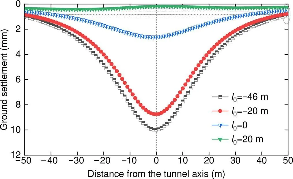
Fig. 8 Transverse ground settlement troughs at different cross-sections
3.3 Subsurface settlement
The subsurface settlement can also be obtained using the proposed model. Fig. 9 shows the variation in ground settlement along the curved tunnel axis at 17 m below the ground surface (i.e. 1 m above the tunnel crown). Compared with the results of the ground settlement (Fig. 6), with increasing depth, the subsurface settlement along the curved tunnel axis induced by the various influencing factors shows little change, whereas the peak displacements increase. Here, the amplification induced by the grouting pressure is the highest, i.e. from 0.4 mm at=0 to 4.3 mm at=17 m, and the total subsurface settlement is about 35.15 mm at the section0=−45 m. Moreover, the transverse settlement troughs (not shown) are asymmetrical about the curved tunnel axis.
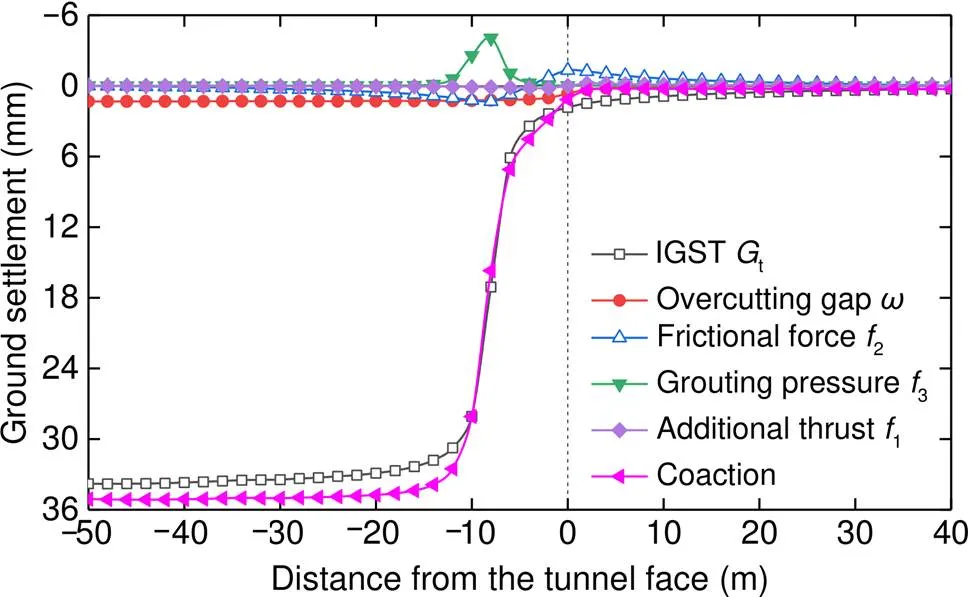
Fig. 9 Subsurface settlements along the curved tunnel axis (z=17 m)
3.4 Parameter analysis of curvature radius
From Eq. (10), the curvature radiusof the curved tunnel affects the overcutting gapat the excavation face during shield tunneling (Table 1). It is necessary to perform a parameter analysis offor the ground settlement under the coaction of the previous factors with the other parameters kept constant.
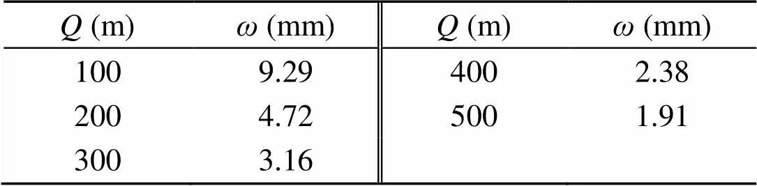
Table 1 Values of ω with different Q
Fig. 10 shows the variation in the total ground settlements along the curved tunnel axis in the cases of five curvature radii (=100 m, 200 m, 300 m, 400 m, and 500 m) as the cutterhead reaches the section0=0. The calculation results of the straight-line tunnel are included for comparison. In particular: (1) During the tunneling of curved tunnels, the total ground settlements above the tunnel axes are larger than that of the straight-line tunnel, mainly because of over-excavation requirements; (2) Asdecreases, the total ground settlement curves move downward. Taking the case of=100 m as an example,we find that the peak ground settlement at the section0=−46 m is about 1.4 mm higher than that of the straight-line tunnel.
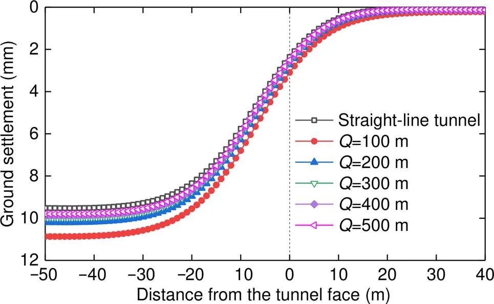
Fig. 10 Ground settlements along the tunnel axis for a straight-line tunnel and five curved tunnels (z=17 m)
With the positions of the curve peaks in Fig. 10 as the cross-sections, Fig. 11 shows the total transverse ground settlement troughs at these cross-sections in the cases of five curvature radii. In particular: (1) During the tunneling of curved tunnels, both the maximum ground settlements and settlement trough widths are greater than those in the straight-line tunnel; (2) The transverse settlement troughs are asymmetrical about the curved tunnel axes, and the offset positions of the maximum settlements are at the inner side of the curved tunnels. For two positions at a distance of 50 m from the curved tunnel (=100 m) axis, the ground settlement at the inner side point is about 0.3 mm greater than that at the outer side point. Fig. 12 illustrates the variation in the maximum ground settlement and offset distance toward the inner side of a curved tunnel witha curvature radius. As shown, these parameters gradually decrease with the increase in, and the change trends are relatively consistent.
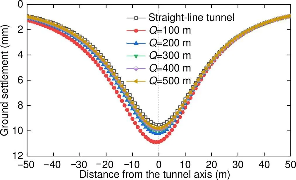
Fig. 11 Transverse ground settlement troughs for a straight-line tunnel and five curved tunnels
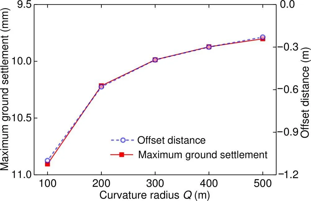
Fig. 12 Variation in the maximum ground settlement and offset distance with Q
According to the calculation, under different conditions of, the variation in the maximum subsurface (=17 m) settlement and its offset distance toward the inner side of the curved tunnel withare similar to those in the case of the ground surface (=0). Unlike the case when=0, the maximum ground settlement (defined as) increases, while its offset distance (defined as) decreases. Taking the case of=100 m as an example, we find that38 mm and=−0.5 m at=17 m, whereas10.9 mm and1.2 m at=0. The relationship between the ratio of the maximum ground settlement to the offset distance (i.e./) andat different depths is plotted in Fig. 13, from which we can clearly confirm the above conclusion:/varies linearly withat different depths, and the curve slope at=17 m is greater than that at=0.
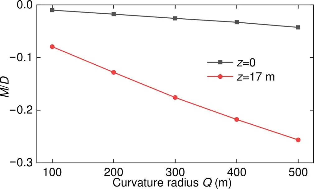
Fig. 13 Relationship curves of M/D and Q
The above parameter analysis of the curvature radius was conducted with the other parameters kept unchanged, such as the shield machine parameters, integrative gap, and construction loadings. To successfully realize the propelling turn of a shield machine of the same type in a curved tunnel, the larger over-excavation is bound to cause more severe nonuniform ground settlement with the decrease in the tunnel curvature radius. Therefore, during the construction of curved tunnels with a small curvature radius, a shield tunneling machine with a good hinge performance is desirable to effectively control the over-excavation and reduce the disturbance of the strata.
4 Comparisons and validation
To prove the reliability of the proposed model, this section presents analytical and numerical comparisons conducted in this study.
4.1 Comparison of ground loss
4.1.1 Comparison of our solution with a classical solution
We could not find a typical analytical solution to the ground settlement induced by ground loss for a curved tunnel. Therefore, we compared our solution with that of a classical solution for a straight-line tunnel. Jiang and Zhao (2005) used 3D image theory to calculate the ground settlement induced by ground loss for a straight-line shield tunnel. Based on the project located between the Xiaobailou and Xiawafang stations on the Tianjin City rail transit line 1, China, the transverse subsurface settlement without considering the grouting effect is illustrated in Fig. 14. Evidently, as long as the curvature radius is sufficiently high, the alignment of the curved tunnel is approximately a straight line.
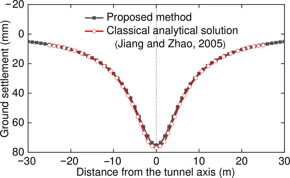
Fig. 14 Transverse subsurface settlements obtained using the proposed method and a classical analytical solution (Jiang and Zhao, 2005)
The result was also obtained, as shown in Fig. 14, by substituting the following parameter values into Eq. (9):=11.85 m,=1000,=3.2 m,=3.1 m,=100 m,=8 m, and=1. As shown, the result obtained using the proposed method was in good agreement with the classical analytical solution.
4.1.2 Comparison of our solution with numerical simulations
As reported by Sagaseta (1988) and Lin et al. (2014), the ground settlement obtained using 3D image theory overestimates the width of the ground settlement trough. Therefore, the analytical solution needs to be modified. We assumed that the ground settlement obtained using the proposed method can be expressed asp(=0). Based on an exponential function (Loganathan and Poulos, 1998), the modified ground settlementmcan be expressed as
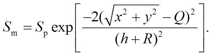
Given that analytical solutions for a curved tunnel have not been reported, we compared our solution with the numerical result. Based on the actual engineering in Zhuhai City, China (Zhang et al., 2020), the excavation of a curved tunnel with a curvature radius of 450 m was simulated through 3D finite element method (FEM) (Fig. 15), with curved model dimensions of 100 m×60 m×120 m. Table 2 summarizes the soil test parameters of the local Zhuhai area. For the purpose of a more straightforward comparison to the analytical solution and an efficient meshing, the input parameters of the soil strata (Table 2) were simplified into one layer in the numerical simulations (Table 3). Specifically, the equivalent Young’s moduluseof the soil layer in Table 3 was obtained via the weighted average of the soil layers in Table 2 (Wang et al., 2018), which can be expressed by
Fig. 15 Finite element model of a curved tunnel (TBM represents the tunnel boring machine)
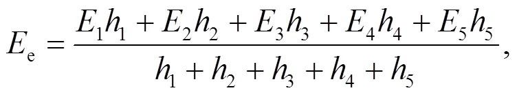
whereEandh(=1, 2, …, 5) are Young’s modulus and thickness of soil layerin Table 2, respectively.
The components in the FEM were simulated using solid elements, the mechanical parameters of which are summarized in Table 3. The soil was assumed to be homogeneous and isotropic with the Mohr-Coulomb yielding criterion. The layer of silty clay accounts for the main proportion of the area surrounding and above the tunnel. The other parameters of the soil layer in Table 3 are in accordance with the values of the layer of silty clay in Table 2. The length of the TBM-shield was 11.2 m, and the shield was assumed to have a cylindrical shape (Lambrughiet al., 2012) with an outside diameter of 8.78 m. Concrete and mortar elements exhibit an elastic behavior. Without considering longitudinal or circumferential joints, the universal segmental linings with an average width of 1.6 m were simulated using continuous elements with a reduced elastic modulus of 25.9 GPa (Zheng et al., 2015). The filling grout between the segmental outer wall and the excavation interface was modeled using annular concrete elements, whereas the overcutting layer with a hemicyclic section (Fig. 5) was on the inner side of the curved tunnel.
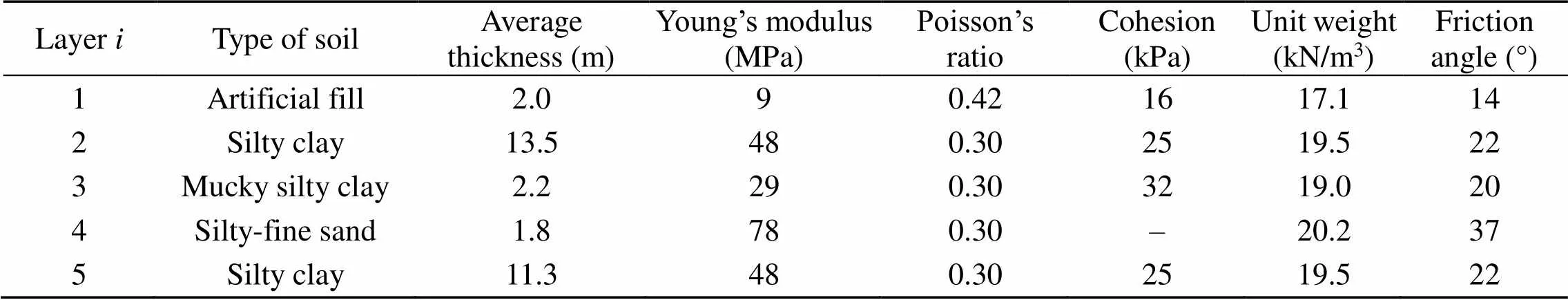
Table 2 Soil test parameters of the local Zhuhai area
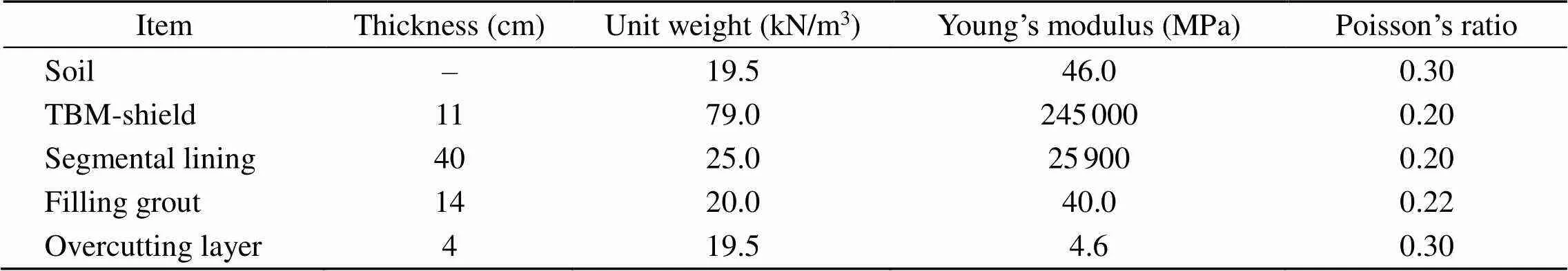
Table 3 Mechanical parameters used in the FEM
A linearly varying pressure induced in the excavation chamber of the TBM-EPB (earth pressure balance) shield was applied to the excavation face. The pressure at the tunnel axis was set to the average value of the horizontal stress at the tunnel crown and stress at the tunnel invert, which was obtained by considering a lateral pressure coefficient,0, equal to 0.4.
A numerical model was established by simulating the excavation of 50 rings (80 m) along the tunnel axis, following a step-by-step technique, as well as by reproducing the tunneling operation and segment installation, based on the scheme introduced by Kavvadaset al. (2017).
Taking the cross-section at the back of the excavation face with a distance of 31 rings (about 50 m) as the steady-state, we obtained the transverse (perpendicular to the tunnel axis) settlement profiles at the ground surface induced by the ground loss via 3D FEM (Fig. 16). The result was also obtained by substituting the following parameter values into Eqs. (9)–(11) and (29):=21.39 m,=450 m,= 4.39 m,=4.25 m,=1.6 m,=100 m,=11.2 m,= 0.52, and=0. As shown in Fig. 16, the peak ground settlement obtained using the modified method in this study was in good agreement with the numerical solution.
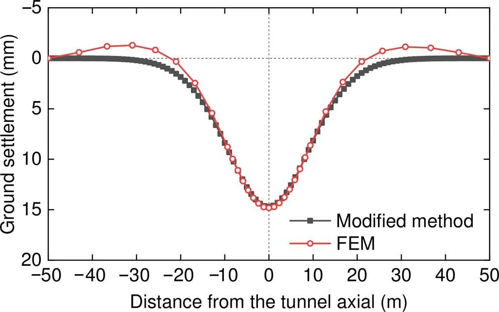
Fig. 16 Transverse ground surface settlements obtained using the modified method and FEM
4.2 Comparison of construction loadings
4.2.1 Degeneration of this study to solutions for a straight-line tunnel
The universal solutions modified from Mindlin’s solutions are beneficial for calculating the ground settlement induced by construction loadings acting on a spatially complicated surface, as long as the spatial parametric equation is given in advance. Taking the classical analytical solutions of a straight-line shield tunnel introduced by Zhu et al. (2014) as an example, we find that the loading area is a circular flat surface with reference to the additional thrust, the solution to which is in accordance with Eq. (19). As for the frictional force (or grouting pressure as shown in Fig. 1), the loading area is a cylindrical surface, which can be expressed by the following parametric equation (=′,=in Eq. (15)):
where′ is a variable representing the length.
By substituting Eq. (31) into Eq. (16), we find that the solution for calculating the ground settlements induced by2is in accordance with that introduced by Zhu et al. (2014), which is expressed as
4.2.2 Numerical comparisons for a curved tunnel
Taking the frictional force, which has a large loading area on the spatial torus, as an example, we simulated the friction-sliding model via a contact pair of the shield skin and excavation interface based on the numerical model presented in Section 4.1.2. In ABAQUS, the Coulomb frictional law was adopted, and the friction coefficient was set to 0.25 (Zheng et al., 2015).
The result was also obtained by substituting the following parameter values into Eqs. (20)–(24):=21.39 m,=450 m,=4.39 m,=11.2 m,=0.3,=17.7 MPa,=19.5 kN/m3,s=0.91, and=8°. As shown in Fig. 17, the ground surface settlement along the tunnel axis obtained using the proposed method in this study was in good agreement with the numerical solution.
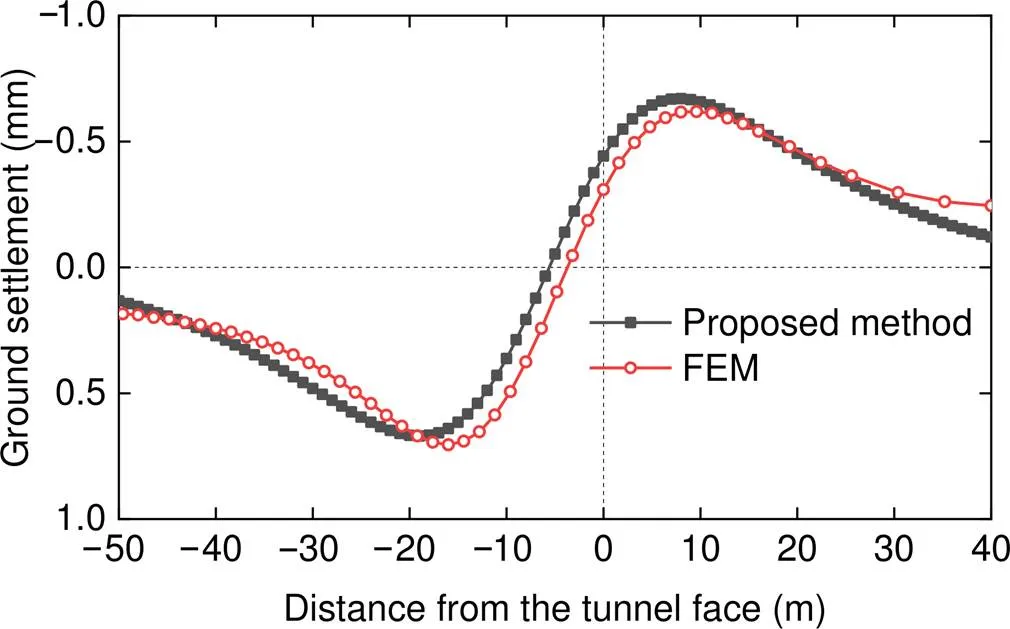
Fig. 17 Axial ground surface settlements obtained using the proposed method and FEM
4.3 Validation
To validate the analytical solution, the result was compared with the monitoring results, numerical results, and Peck formula results obtained by Lu et al. (2018). Based on the project located between the Wangfuzhuang and Dayangzhuang stations on the Tianjin City rail transit R1 line, theoretical analysis was carried out using the corresponding parameters given by Lu et al. (2018). Thick alluvial viscous land layers are widely distributed in this area, and the thickness of quaternary overburden is greater than 50 m. Within the range of 4 m surrounding the tunnel, the soil comprises mainly loess, silty clay, and clay, the cohesiveness and friction angle of which are 40 to 52 kPa, and 20° to 28°, respectively.
By setting equivalent layers with different thicknesses and an uneven hydraulic jack thrust on both the sides of the curved tunnel, we could realize the propelling turn in the numerical calculation model. The same detailed information with respect to the monitoring data and numerical model obtained by Lu et al. (2018) is presented in Section 3. The mechanical parameters of the numerical model are summarized in Table 4.
Under the coaction of the soil loss and construction loadings, the numerical analysis results show that the maximum transverse ground surface settlement appears on the left (inner side) of the curved tunnel, consistent with the analytical results. Considering the monitoring data of the ground settlements at the five stable cross-sections (denoted by DBC7, DBC10, DBC11, DBC12, and DBC14) at the curved tunnel, the ground settlements under the influence of all the factors obtained from our analyticalanalysis were compared with field monitoring data (Fig. 18).
The maximum ground settlements obtained using the numerical simulation and Peck empirical formula were 13 mm and 16 mm, respectively, which significantly exceed the range of the measured results (i.e. 7.8 to 9.2 mm). However, the maximum ground settlement (9.98 mm) deduced by our analytical analysis was close to the monitored results. In addition, the transverse ground settlement trough was in good agreement with the fitting curve of the monitoring data, all of which reflect the asymmetry phenomenon in that the offset position of the maximum settlement was on the inner side of the curved tunnel. Thus, the reliability of our analytical analysis was validated.
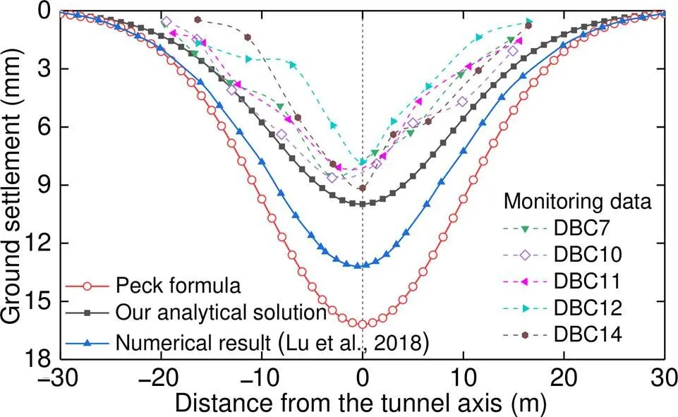
Fig. 18 Validation of our analytical solution
5 Conclusions
In this study, we derived analytical solutions to the ground settlement induced during curved shield tunneling. The following conclusions were drawn from the results:
1. Considering the “integrative gap at shield tail” (IGST) and overcutting gap of a curved tunnel, a calculation model for the ground settlement induced by ground loss was established based on 3D image theory.
2. By modifying Mindlin’s solutions, we derived analytical solutions to the ground settlement due to construction loadings based on the theoretical formula of the ground displacement induced by a unit area of force acting on the spatial surface.
3. The ground settlements along the curved tunnel axis induced by the IGST, frictional force, grouting pressure, and additional thrust were found to be consistent with those in the cases of straight-line tunnels. However, unlike a straight-line tunnel, the transverse ground settlement troughs induced by these factors were nonsymmetric about the tunnel axis due to the geometry characteristics of the curved tunnel. The peak ground settlement due to the IGST, which contributed the most to the total ground settlement, tended to be offset toward the inner side of the curved tunnel. The ground settlement on the inner side was greater than that on the outer side.
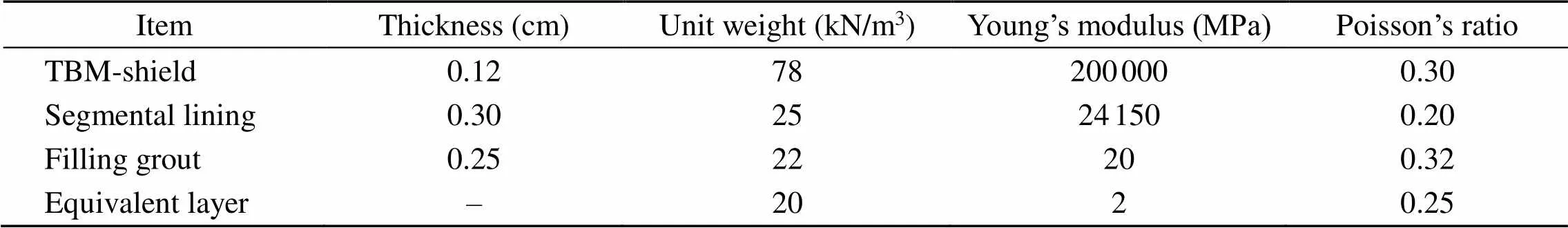
Table 4 Mechanical parameters of the numerical model
4. Given the need for over-excavation during curved tunneling, the maximum ground settlements and settlement trough widths under the coaction of the various factors were greater than those of straight-line tunnels. The maximum ground settlement and offset distance toward the inner side of the curved tunnel gradually reduced to the calculation result of the straight-line tunnel as the curvature radius increased.
5. The variation in the subsurface settlements along the curved tunnel axial induced by various influencing factors was consistent with that at the ground surface, whereas the displacement peaks increased. The variation in the maximum ground settlement and offset distance with the curvature radius exhibited no change at different soil depths (i.e. decreased with the increase in the curvature radius, and the change trends were relatively consistent), except that the maximum settlement was greater and the offset distance was smaller in deeper soils.
The analytical solution is valid for the greenfield condition. If a building exists nearby the tunnel excavation, the equations proposed in this study cannot be used due to the existing building load.
Contributors
Shao-hua LI and Peng-fei LI designed the research. Shao-hua LI performed the computer programs and the numerical simulations. Shao-hua LI wrote the first draft of the manuscript. Ming-ju ZHANG and Peng-fei LI revised and edited the final version.
Conflict of interest
Shao-hua LI, Peng-fei LI, and Ming-ju ZHANG declare that they have no conflict of interest.
Alonso EE, Josa A, Ledesma A, 1984. Negative skin friction on piles: a simplified analysis and prediction procedure., 34(3):341-357. https://doi.org/10.1680/geot.1984.34.3.341
Alsahly A, Stascheit J, Meschke G, 2016. Advanced finite element modeling of excavation and advancement processes in mechanized tunneling., 100:198-214. https://doi.org/10.1016/j.advengsoft.2016.07.011
Attewell PB, Woodman JP, 1982. Predicting the dynamics of ground settlement and its derivatives caused by tunnelling in soil., 15(8):13-22.
Attewell PB, Yeates J, Selby AR, 1987. Soil movements induced by tunnelling and their effects on pipelines and structures: P. B. Attewell, J. Yeates, and A. R. Selby. Blackie & Son Ltd. 1986. 352 pp. £37.00., 2(1):102. https://doi.org/10.1016/0886-7798(87)90195-7
Chi SY, Chern JC, Lin CC, 2001. Optimized back-analysis for tunneling-induced ground movement using equivalent ground loss model., 16(3):159-165. https://doi.org/10.1016/S0886-7798(01)00048-7
Festa D, Broere W, Woude S, et al., 2012. Tunnel-boring process in urban environment: modeling for reliability— a kinematic study.: Viggiani G (Ed.), Geotechnical Aspects of Underground Construction in Soft Ground. CRC Press, London, UK, p.813-818. https://doi.org/10.1201/b12748-109
González C, Sagaseta C, 2001. Patterns of soil deformations around tunnels. Application to the extension of Madrid Metro., 28(6-7):445-468. https://doi.org/10.1016/s0266-352x(01)00007-6
Huynh TN, Chen J, Sugimoto M, 2016. Analysis on shield operational parameters to steer articulated shield., 2(42): 1497-1500. https://doi.org/10.3208/jgssp.ATC6-11
Jiang X, Zhang XH, Chen A, et al., 2018. Ground surface deformation analysis of quasi rectangular EPB shield tunneling. Proceedings of GeoShanghai 2018 International Conference, p.103-111. https://doi.org/10.1007/978-981-13-0017-2_10
Jiang XL, Zhao ZM, 2005. 3-D analytical method used to calculate shield tunneling induced soil displacements., 22(2):1-4 (in Chinese). https://doi.org/10.3969/j.issn.2095-0985.2005.02.001
Kasper T, Meschke G, 2006. On the influence of face pressure, grouting pressure and TBM design in soft ground tunnelling., 21(2):160-171. https://doi.org/10.1016/j.tust.2005.06.006
Kavvadas M, Litsas D, Vazaios I, et al., 2017. Development of a 3D finite element model for shield EPB tunnelling., 65:22- 34. https://doi.org/10.1016/j.tust.2017.02.001
Kong FC, Lu DC, Du XL, et al., 2019. Elastic analytical solution of shallow tunnel owing to twin tunnelling based on a unified displacement function., 68:422-442. https://doi.org/10.1016/j.apm.2018.11.038
Lambrughi A, Rodríguez LM, Castellanza R, 2012. Development and validation of a 3D numerical model for TBM-EPB mechanised excavations., 40:97-113. https://doi.org/10.1016/j.compgeo.2011.10.004
Lee KM, Rowe RK, Lo KY, 1992. Subsidence owing to tunnelling. I. Estimating the gap parameter., 29(6):929-940. https://doi.org/10.1139/t92-104
Li PF, Wang F, Fan LF, et al., 2019a. Analytical scrutiny of loosening pressure on deep twin-tunnels in rock formations., 83:373-380. https://doi.org/10.1016/j.tust.2018.10.007
Li PF, Wang F, Zhang CP, et al., 2019b. Face stability analysis of a shallow tunnel in the saturated and multilayered soils in short-term condition., 107:25-35. https://doi.org/10.1016/j.compgeo.2018.11.011
Li PF, Zou HH, Wang F, et al., 2020. An analytical mechanism of limit support pressure on cutting face for deep tunnels in the sand., 119:103372. https://doi.org/10.1016/j.compgeo.2019.103372
Li SH, Li PF, Zhang MJ, et al., 2020. Influence of approaching excavation on adjacent segments for twin tunnels., 10(1):98. https://doi.org/10.3390/app10010098
Li W, Zhang CP, Zhu WJ, et al., 2019. Upper-bound solutions for the face stability of a non-circular NATM tunnel in clays with a linearly increasing undrained shear strength with depth., 114:103136. https://doi.org/10.1016/j.compgeo.2019.103136
Liang RZ, Xia TD, Lin CG, et al., 2015. Analysis of ground surface displacement and horizontal movement of deep soils induced by shield advancing., 34(3):583-593 (in Chinese). https://doi.org/10.13722/j.cnki.jrme.2015.03.016
Lin CG, Xia TD, Liang RZ, et al., 2014. Estimation of shield tunnelling-induced ground surface settlements by virtual image technique., 36(7):1438-1446 (in Chinese). https://doi.org/10.11779/CJGE201408009
Lo KY, Ng RMC, Rowe RK, 1984. Predicting settlement due to tunnelling in clay. Proceedings of the Tunnelling in Soil and Rock,ASCE Geotech III Conference, p.46-76.
Loganathan N, Poulos HG, 1998. Analytical prediction for tunneling-induced ground movements in clays., 124(9): 846-856. https://doi.org/10.1061/(asce)1090-0241(1998)124:9(846)
Lu DC, Kong FC, Du XL, et al., 2019. A unified displacement function to analytically predict ground deformation of shallow tunnel., 88:129-143. https://doi.org/10.1016/j.tust.2019.03.005
Lu LH, Sun JC, Zhou GF, et al., 2018. Research on the surface deformation prediction for curved shield construction in clay stratum., 35(5):99-105 (in Chinese). https://doi.org/10.3969/j.issn.1006-2106.2018.05.017
Mair RJ, Taylor RN, Bracegirdle A, 1993. Subsurface settlement profiles above tunnels in clays., 43(2):315-320. https://doi.org/10.1680/geot.1993.43.2.315
Migliazza M, Chiorboli M, Giani GP, 2009. Comparison of analytical method, 3D finite element model with experimental subsidence measurements resulting from the extension of the Milan underground., 36(1-2):113-124. https://doi.org/10.1016/j.compgeo.2008.03.005
Mindlin RD, 1936. Force at a point in the interior of a semi-infinite solid., 7(5):195- 201. https://doi.org/10.1063/1.1745385
Ng RMC, Lo KY, Rowe RK, 1986. Analysis of field performance—the Thunder Bay tunnel., 23(1):30-50. https://doi.org/10.1139/t86-005
Peck RB, 1969. Deep excavations and tunneling in soft ground. Proceedings of the 7th International Conference on Soil Mechanics and Foundations, p.225-290.
Pinto F, Whittle AJ, 2014. Ground movements due to shallow tunnels in soft ground. I: analytical solutions., 140(4): 04013040. https://doi.org/10.1061/(ASCE)GT.1943-5606.0000948
Potyondy JG, 1961. Skin friction between various soils and construction materials., 11(4):339-353. https://doi.org/10.1680/geot.1961.11.4.339
Sagaseta C, 1987. Analysis of undraind soil deformation due to ground loss., 37(3):301-320. https://doi.org/10.1680/geot.1987.37.3.301
Sagaseta C, 1988. Discussion: analysis of undrained soil deformation due to ground loss., 38(4):647- 649. https://doi.org/10.1680/geot.1988.38.4.647
Sigl O, Atzl G, 1999. Design of bored tunnel linings for Singapore MRT North East Line C706., 14(4):481-490. https://doi.org/10.1016/S0886-7798(00)00010-9
Sugimoto M, Sramoon A, Konishi S, et al., 2007. Simulation of shield tunneling behavior along a curved alignment in a multilayered ground., 133(6):684-694. https://doi.org/10.1061/(asce)1090-0241(2007)133:6(684)
Tang XW, Zhu J, Liu W, et al., 2010. Research on soil deformation during shield construction process., 29(2):417- 422 (in Chinese).
Verruijt A, Booker JR, 1996. Surface settlements due to deformation of a tunnel in an elastic half plane., 46(4):753-756. https://doi.org/10.1680/geot.1996.46.4.753
Wang HN, Wu L, Jiang MJ, et al., 2018. Analytical stress and displacement due to twin tunneling in an elastic semi-infinite ground subjected to surcharge loads., 42(6):809-828. https://doi.org/10.1002/nag.2764
Wei G, Hong J, Wei XJ, 2012. Research on three-dimensional soil deformation induced by Double-O-Tube shield tunneling., 5(4):4-8.
Wei G, Pang SY, Zhang SM, 2013. Prediction of ground deformation induced by double parallel shield tunneling., 6(13):91-98.
Wongsaroj J, Borghi FX, Soga K, et al., 2005. Effect of TBM driving parameters on ground surface movements on Channel Tunnel Rail Link Contract 220. Proceedings of the 5th International Symposium on Geotechnical Aspects of Underground Construction in Soft Ground, p.335-341.
Zhang MJ, Li SH, Li PF, 2020. Numerical analysis of ground displacement and segmental stress and influence of yaw excavation loadings for a curved shield tunnel., 118:103325.https://doi.org/10.1016/j.compgeo.2019.103325
Zhang QQ, Li SC, Li LP, et al., 2013. Simplified method for settlement prediction of pile groups considering skin friction softing and end resistance hardening., 32(3):615- 624 (in Chinese). https://doi.org/10.3969/j.issn.1000-6915.2013.03.020
Zhang XH, Chen JX, Bai Y, et al., 2018. Ground surface deformation induced by quasi-rectangle EPB shield tunneling., 52(2):317-324 (in Chinese). https://doi.org/10.3785/j.issn.1008-973X.2018.02.014
Zhang ZG, Huang MS, 2014. Geotechnical influence on existing subway tunnels induced by multiline tunneling in Shanghai soft soil., 56:121- 132. https://doi.org/10.1016/j.compgeo.2013.11.008
Zheng G, Lu P, Diao Y, 2015. Advance speed-based parametric study of greenfield deformation induced by EPBM tunneling in soft ground., 65:220-232. https://doi.org/10.1016/j.compgeo.2014.12.013
Zhu JF, Xu RQ, Liu GB, 2014. Analytical prediction for tunnelling-induced ground movements in sands considering disturbance., 41:165-175. https://doi.org/10.1016/j.tust.2013.12.004
https://doi.org/10.1631/jzus.A2000120
TU744; U455.43
*Project supported by the National Natural Science Foundation of China (Nos. 51738010, 51978018, and 51978019)
Apr. 1, 2020;
Aug. 31, 2020;
Mar. 3, 2021
 Journal of Zhejiang University-Science A(Applied Physics & Engineering)2021年4期
- Journal of Zhejiang University-Science A(Applied Physics & Engineering)的其它文章
- Development of electric construction machinery in China: a review of key technologies and future directions*
- Pile foundation of high-speed railway undergoing repeated groundwater reductions*
- Stabilization mechanisms of lifted flames in a supersonic stepped-wall jet combustor*
- A parametric study on unbalanced moment of piston type valve core*