
A parametric study on unbalanced moment of piston type valve core*
2021-04-14 14:06JinyuanQIANJuanMUCongweiHOUZhijiangJIN
Jin-yuan QIAN, Juan MU, Cong-wei HOU, Zhi-jiang JIN†‡
A parametric study on unbalanced moment of piston type valve core*
Jin-yuan QIAN1,2, Juan MU1, Cong-wei HOU1, Zhi-jiang JIN†‡1
Institute of Process Equipment, College of Energy Engineering, Zhejiang University, Hangzhou 310027, China State Key Laboratory of Fluid Power and Mechatronic Systems, Zhejiang University, Hangzhou 310027, China †E-mail: jzj@zju.edu.cn
In this paper, the piston type valve core and the unbalanced moment on its bottom are studied. To decrease the influence of non-common geometrical factors, a simplified model of the piston type globe valve is proposed in this study. Based on the computational fluid dynamics (CFD) method, the effects of different geometrical parameters on the unbalanced moment existing on the bottom of the valve core, which include the bending radius of the inlet flow channel, the diameter of the special-shaped pipe, and the height of the valve core, are studied. Finally, the effects of geometrical parameters on the unbalanced moment on the bottom of the valve core are clarified by correction and variation classification and provide a basis for further optimizing the structure of the piston type valve. The results show that the unbalanced moment decreases with the increase of the bending radius of the inlet flow channel, but increases with the increase of the diameter of the special-shaped pipe and the height of the valve core. Moreover, the relation between the unbalanced moment and flow rate is proposed.
Piston type valve core; Unbalanced moment; Geometrical parameters; Computational fluid dynamics (CFD)
1 Introduction
The piston type valve core is one of the most important elements in the valve, and depends on the pressure difference of the valve core and the spring force to open and close. It is commonly used in globe valves, check valves, pressure reducing valves, and so forth. Owing to the irregular shape of the inlet flow channel, there is an unbalanced moment acting on the bottom of the valve core. The existence of this unbalanced moment leads the valve core to have a tendency to overturn, and even causes deformation of the valve stem and valve core, which affects the sealing between the valve core and the valve seat and causes internal leakage of the valve. Therefore, it is important to explore the cause of the unbalanced moment on the bottom of the piston type valve core.
The geometries of the valve body and the valve internal parts have a great influence on the flow in the valve. Therefore, some scholars have performed experimental analysis and numerical simulation to analyze the influence of valve geometries on the valve characteristics and have proposed geometrical optimization to improve them. The minimization of the flow force was studied which opposes valve opening by considering design parameters related to the spool geometry of the proportional directional control valve (Amirante et al., 2014). The optimal spool geometry and maximal reduction of the axial flow forces were proposed by considering a combination of all geometry parameters and thus improved the overall performance of the hydraulic on/off seat valve (Simic and Herakovic, 2015). The effect on its design and usage of the valve plug cone angle of the global control valve was studied by simulation and experiment methods (Lin et al., 2015). The problem of clamping stagnation caused by warpage-deformation and fit clearance reduction of the valve core and valve sleeve of a double flapper-nozzle servo valve was studied, by the method of heat-fluid-solid coupling analysis and experiment (Zhao et al., 2015). A numerical investigation on the flow force and cavitation characteristics inside water hydraulic poppet valves was presented and the effects of geometric parameters were analyzed; otherwise, an optimization of the poppet geometry was proposed (Han et al., 2017, 2018). A geometry optimization of the spool in a single-stage rotary servo valve was presented to re-duce the steady flow moments. Similarly, this paper will conduct parametric research on the unbalanced moment of the piston type valve core and explore the effects of the valve characteristic geometrical parameters on that moment (Wang H. et al., 2019). To reduce the particle erosion resistance and improve the service life of the valve core, a novel valve core structure for a water hydraulic valve was designed, which was inspired by the convex domes of a conch shell and the fractal structure of Romanesco broccoli. The numerical and experimental results showed that the bionic structure could effectively improve the anti-erosion property of the valve core and protect the sealing face on the valve core from wear (Wang HH. et al., 2019). Researchers also focused on the cavitation in the sleeve-regulating valve and investigated the effects of different valve core shapes, including flat bottom, ellipsoid, circular truncated cone, and cylinder, on cavitation by using a cavitation model. The results showed that the cavitation strengths of the ellipsoidal valve core and the cylindrical valve core are greater than that of the other two valve cores (Jin et al., 2020). The effect of the guiding plate on flow characteristics in a ball valve was studied. The results showed that setting guiding plates in the ball valve behind the valve core effectively reduced the adverse effect of high-speed jet flows caused by the small degree of opening, thereby reducing the internal erosion, increasing the stability of valve downstream flow efficiently, and improving the valve performance finally (Wang et al., 2020).
In addition to the geometries of the valve, the opening or closing torque of the valve and the internal flow force of the valve have a great impact on its performance. Therefore, many researchers have studied the flow force or torque inside the valve. For the flow force acting on the spool, the valve-opening characteristics and the determination of flow force applied on the valve disk in a safety relief valve was studied (Kourakos et al., 2013). The flow forces acting on the spool of a proportional-control valve in the initial phase of the spool gap opening were studied (Lisowski et al., 2018). The flow forces acting on the spool were reduced and the actuation forces were decreased by proposing a new methodology for the design of the spool surfaces of four-way three- position directly operated proportional directional valves based on experimental validation (Amirante et al., 2016). A seat valve using a damping sleeve with orifices to minimize the axial flow forces on the spool was proposed, and the simulation results fitted the experimental results well (Zhang et al., 2018). The pressure transient flow force acting on hydraulic spool valves was studied experimentally and the result showed that the flow forces due to pressure transient effects could be comparable in magnitude to the steady flow forces acting on the valve (Manring and Zhang, 2012). A 3D computational fluid dynamics (CFD) model was presented to study the torque and the fluid-dynamic force acting on the spool of a hydraulic valve and a flow-control valve, respectively. The fluid force in a valve is a form of flow characteristics. The analysis of fluid force in a valve can provide a basis for improving its performance and solving existing problems in it (Frosina et al., 2016, 2017).
In general, there has been much significant research on valve flow characteristics, opening and closing characteristics, and valve fluid force. However, due to the complexity of the flow inside the valve, it is a great challenge to study the theoretical analysis and formation mechanism of that flow. Current research ignores the mechanism of the complex flow inside the valve, and pays little attention to the unbalanced force at the bottom of the valve core.
Therefore, in this paper, a simplified model of the piston type globe valve is proposed to investigate the characteristics of the unbalanced moment. Based on the steady-flow field model of the simplified model, the flow characteristics and the moment characteristics are investigated. The effects of the geometrical parameters, including the bending radius of the inlet flow channelf, the diameter of the special-shaped pipe, and the height of the valve core, on the unbalanced moment of the bottom of the valve core are studied. In the end, the relationship between the unbalanced moment and the flow rate is obtained. This work is helpful for guiding further geometrical optimization for reducing unbalanced moments in piston type valve cores.
2 Numerical model
2.1 Simplified model
Fig. 1a shows a geometrical model of the globe valve with a piston type valve core. The globe valve is one of the cut-off valves, which can realize the transportation, cut-off, and regulation of a medium. It applies pressure to the valve core in the axial direction through the valve stem to make the sealing surfaces of the valve core and valve seat fit closely, so as to prevent the medium from leaking along the gap between the sealing surfaces. In order to reduce the number of elements in the numerical model and reduce the calculation cost, the piston globe valve is simplified as displayed in Fig. 1b. The simplified model extracts the common features of the structure of piston type valves, which makes the results also applicable to other types of piston valves.
According to previous research, the unbalanced moment on the bottom of the piston type valve core is mainly caused by the flow channel of the horizontal valve body, and the flow rate of the valve is the main factor affecting the unbalanced moment (Hou et al., 2019). In view of the above factors, three characteristic structural parameters are selected in this study: the bending radius of the inlet flow channelf, the diameter of the special-shaped pipe, and the height of the valve core.
In addition to the above three characteristic parameters, the other parameters are fixed. The diameters of the inlet and the outlet are both 100 mm, the diameter of the valve core is 80 mm, and the thickness of the valve core is 5 mm. With the changes off,, and, there are 13 models in this simulation. The precise parameters of each model are presented in Table 1.
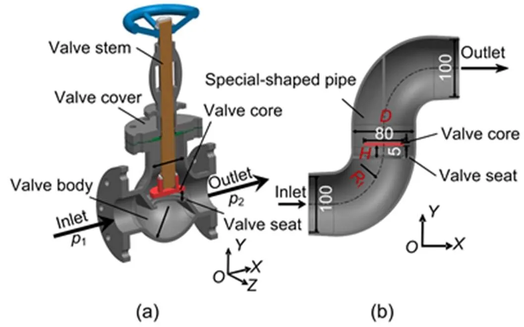
Fig. 1 Structures of the piston type globe valve (a) and the simplified model (b) (unit: mm)
1is the inlet pressure;2is the outlet pressure
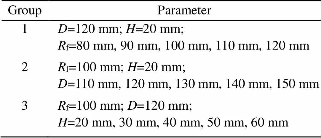
Table 1 Parameters of each model
2.2 Mathematical model
The medium in the valve is water, which is assumed as an incompressible fluid. Since temperature is not involved in this simulation, an energy equation is not needed. The standard continuity and momentum equations are solved first.
Continuity equation:
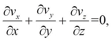
wherev, v, and vare the velocity components of the fluid element in the,, anddirections, respectively.
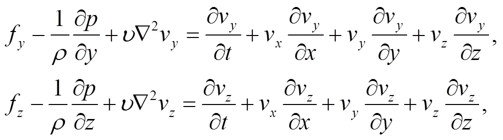
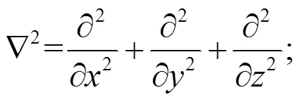
Momentum equation:
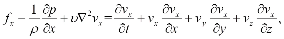
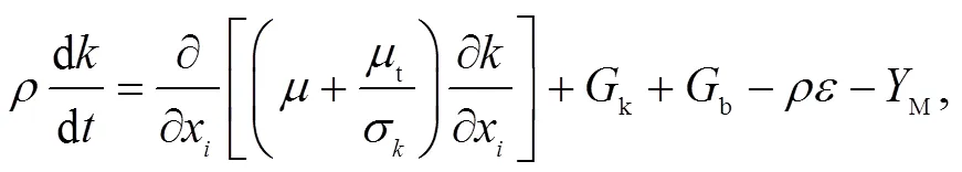
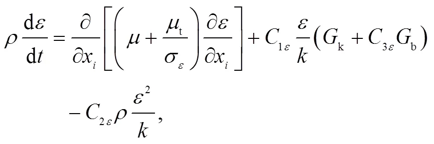
The standardturbulence model needs to solve the equation of the turbulent kinetic energyand the dissipation rate. The equation for the turbulent kinetic energy is derived by a precise equation, but the equation of the dissipation rate is obtained by physical reasoning and mathematical simulation of similar primitive equations. The equations of the turbulent kinetic energyand the dissipation ratein the standardturbulence model are as follows:

2.3 Mesh and solution setting
Fig. 2 shows the simplified flow field model of the piston type valve and the grid generation of the simplified model whosef=100 mm,=120 mm, and=20 mm. ANSYS ICEM is used to generate the mesh. Owing to the complex structure, the model uses an unstructured tetrahedral grid. In addition, a three-layer boundary layer grid is set on the wall surface to improve the accuracy of calculation. To obtain the data of the flow rate in all directions near the bottom of the valve core, a torus is made between the valve core and the separator. It is split into 20 parts. The boundary conditions of all 20 parts are set as the interior. Accordingly, the bottom surface of the valve core is also divided into 20 parts.
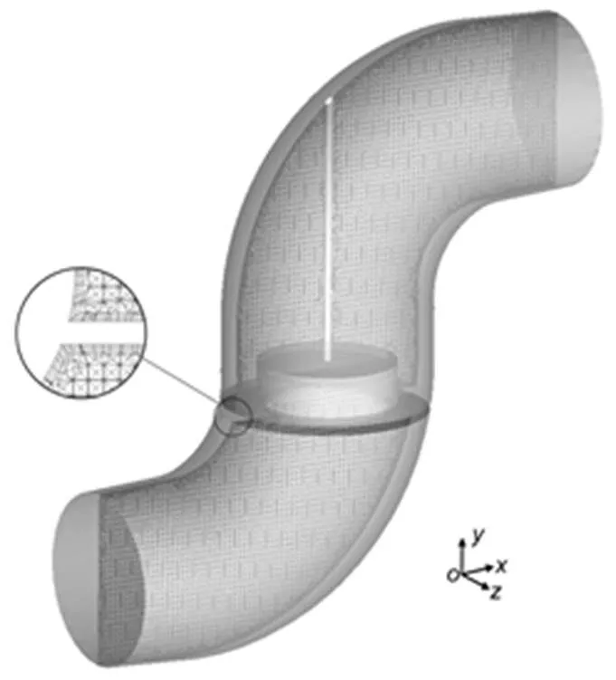
Fig. 2 Grid of the flow channel model
To ensure the accuracy and improve the efficiency of calculation, a grid independence check should first be completed. The maximum grid size is finally determined by adjusting the maximum grid size to change the grid number and taking the outlet flow rate as a reference. Fig. 3 shows the results of outlet flow rate with different maximum grid sizes. When the maximum grid size is lower than 3.6 mm, the value of outlet flow rate does not change, and it can be considered that the grid number no longer affects the calculation results. Therefore, 3.6 mm is selected as the maximum grid size, and that is used in the remaining models with different geometrical parameters.
The simulation is carried out via FLUENT. The coupling method of pressure and velocity uses the semi-implicit method for pressure linked equation (SIMPLE) algorithm, and all the discrete format uses the second-order upwind format. Although the flow velocity is not the same in all sections, the velocity of all sections does not change with time. The velocity only changes with spatial position and is independent of time. A steady calculation model is chosen in this simulation. The Reynolds number is between 8.00×10⁴and 1.60×10⁶. The flow is completely turbulent and its vorticity is small, so the standardturbulence model is chosen. The boundary condition is set as pressure-inlet and pressure-outlet, and the rest of the surfaces are non-slip surfaces. This study focuses on the globe valve under low pressure conditions, and the inlet pressure is set to 0.25 MPa while the outlet pressure is set to atmospheric pressure, namely 0.1 MPa. The medium is water at normal temperature. Its density is 998.2 kg/m3, and its viscosity is 1.001 kg/(m·s).
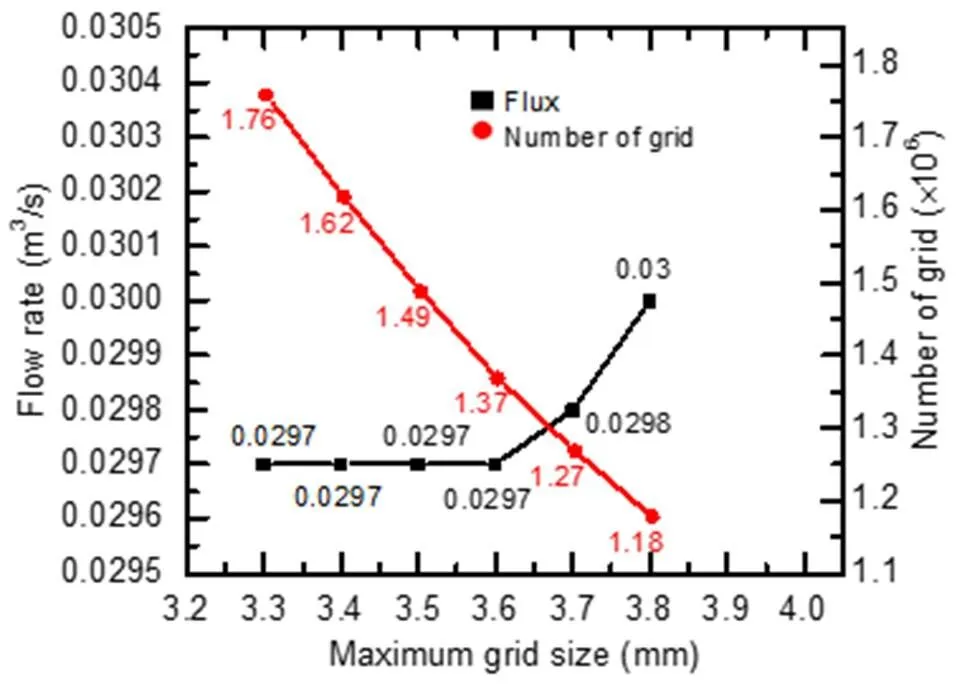
Fig. 3 Grid independence check
3 Results and discussion
3.1 Comparison with similar simulations
To verify the accuracy of the simulation, this paper studies the pressure characteristics of the valve core and the flow characteristics under different heights of the valve core whenf=100 mm and=120 mm. The variation characteristics of the pressure difference between the upper and lower surfaces of the valve core and the flow rate at the valve outlet, with the height of the valve core are analyzed, and the pressure distribution on the bottom of the valve core is analyzed when the height of the valve core is 20 mm.
Table 2 shows the pressure difference under heights of the valve core of 15 to 65 mm. It can be seen that when the height of the valve core is 15 mm, the pressure difference is the largest, at 0.2698 MPa. With the increase of the height of the valve core, the pressure difference decreases gradually, and the variation range decreases from 0.0043 to 0.0001 MPa. Fig. 4 shows the fluid force and the pressure difference under different heights of the valve core. It is obvious that the change of the fluid force is consistent with the change of pressure difference. The simulation results in this study are compared with those of the pilot control globe valve (PCGV) with a similar structure. The flow and cavitation characteristics of PCGV under different spool displacements were studied (Qian et al., 2016a). The pressure difference between the upper and lower surfaces of the valve core was obtained when the inlet velocity was 3 m/s and the displacement of the valve core was 5–25 mm. The pressure difference range was 0.0183–0.1634 MPa, which is the same order of magnitude as the pressure difference simulated in this paper.
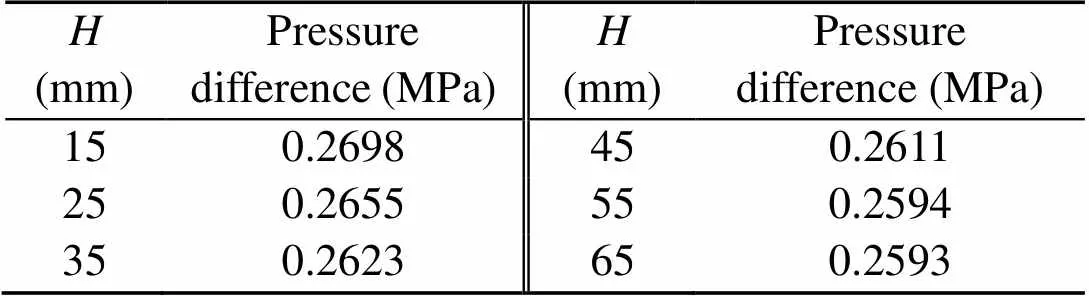
Table 2 Pressure differences under different heights of the valve core
Fig. 5 shows the pressure distribution at the bottom of the valve core when the height of the valve core is 20 mm. As shown in Fig. 5, the pressure distribution is asymmetric. The pressure at the bottom of the valve core near the outlet side is greater than that near the inlet side. The pressure distribution at the bottom of the valve core is compared with that of PCGV studied by Qian et al. (2016b). In the two simulation results, the pressures of the bottom of the valve core present the same unbalanced phenomenon, and the right side pressures are both greater than the left side pressures. The above results again show the reasonableness of the simplified model.
It can be seen from Fig. 6a that the piston type globe valve has fast opening flow characteristics. That is to say, there is a large flow rate change when the opening is small. With the increase of the opening, the flow rate change is very small. The simulation results are compared with the flow characteristics under different pressure differences (D) obtained by Nguyen et al. (2020), as shown in Fig. 6b. The pressure distribution and flow coefficient of a globe valve were investigated with a series of experiments conducted in a flow test loop (Nguyen et al., 2020). Comparing Figs. 6a and 6b, it can be found that the globe valve in the literature (Nguyen et al., 2020) and the piston globe valve in this paper have the same flow characteristics.
By comparing the simulation results of this study with the above research (Nguyen et al., 2020), the reliability and accuracy of the simulation in this study are confirmed.
3.2 Effects of the bending radius of the inlet flow channel
The unbalanced moment on the bottom of the valve core is mainly caused by the irregular shape of the inlet flow channel.fis the dominant parameter of the inlet flow channel, and obviously affects the flow pattern, vorticity, and turbulence level of the fluid near the bottom of the valve core. Fig. 7 presents the velocity and streamline distributions on the symmetrical surface of the models with differentf. As shown in Fig. 7, the flow velocity near the bottom of the valve core is the smallest at the center of the bottom of the valve core. The flow velocity increases gradually along the radial direction and reaches a maximum at the outermost part of the valve core. The fluid velocity near the bottom center of the valve core is minimal and within 4 m/s. This area is called the “low-speed zone.” It can be seen from Fig. 7 that the angle between the streamlines and the bottom of the valve core is larger in the “low-speed zone” than that in other areas, which means that the “low-speed zone” is the area that is directly impacted by the fluid. The momentum of fluid in this area decreases greatly, i.e. the bottom of the valve core in this area is subjected to a larger fluid force and the pressure on the bottom of the valve core in this area is greater. The “low-speed zone” can also be regarded as the boundary region of flow direction. The fluid on the left side of the “low-speed zone” flows out from the side near the inlet, while the fluid on the right side flows out from the side near the outlet.
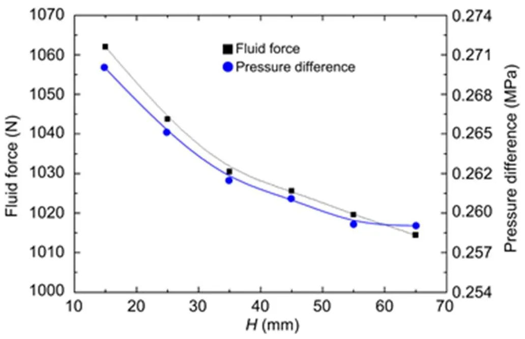
Fig. 4 Fluid force and pressure difference under different heights of the valve core
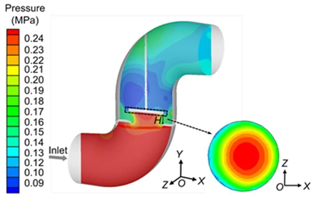
Fig. 5 Pressure contour on the bottom of the valve core under H=20 mm
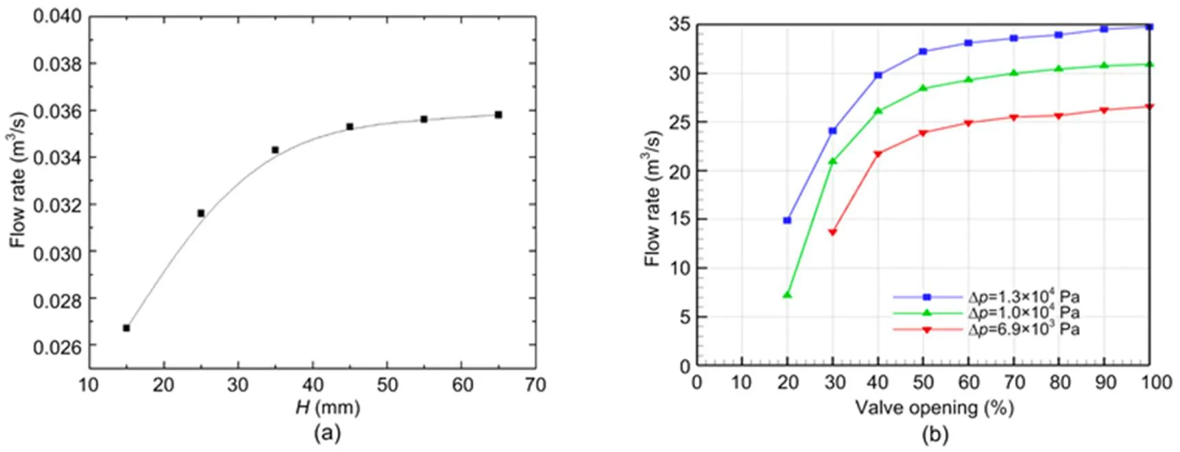
Fig. 6 Flow characteristic curves of the globe valve
(a) Piston globe valve; (b) Globe valve in the literature (Nguyen et al., 2020)
It can be seen from Fig. 7a that there is an obvious difference between the inlet and outlet velocities. For incompressible fluid, the reason is that the velocity of the fluid after flowing through the valve increases due to the pressure difference between inlet and outlet. However, due to the law of mass conservation, the fluid does not fully fill the outlet flow channel. In other words, the effective flow area of the outlet is less than the cross-sectional area of the outlet flow channel.
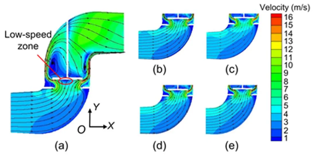
Fig. 7 Velocity profiles and streamlines on the symmetry plane
(a)f=80 mm; (b)f=90 mm; (c)f=100 mm; (d)f=110 mm; (e)f=120 mm
Obviously, theflow rate at the outlet side is larger than that at the inlet side, as shown in Fig. 8. The orthogonal coordinate system in Fig. 8 is defined as follows: the center of the bottom of the valve core as the origin, the side of the outlet as the-axis positive direction, the line perpendicular to the bottom of the valve core as the-axis direction and above it is positive, the outward vertical to the symmetrical surface as the-axis positive direction. Moreover, the average velocity at the outlet side is larger than that at the inlet side, that is to say that the dynamic pressure at the outlet side is higher. The larger flow rate and the higher dynamic pressure make the pressure on the bottom of the valve core at the outlet side larger. With the increase off, the fluid distribution near the bottom of the valve core becomes more uniform, and the “low-speed zone” moves towards the center of the bottom of the valve core. Therefore, the unbalanced pressure on the bottom of the valve core is reduced.
Under the influence of an irregular inlet flow channel, the fluid flows more through the valve core from the side near the outlet after impacting the bottom of the valve core. Where the flow rate is larger, the bottom of the valve core is naturally subjected to greater impact. From Fig. 8, in the positive direction of the-axis, the flow rate in all directions is maintained in the range of 0.0016–0.0018 m3/s, while in the negative direction of the-axis, the flow rate is not more than 0.0015 m3/s. That is to say, the unbalanced flow rate distribution is mainly manifested along the-axis while along the-axis the flow distribution is more balanced. Whenf= 80 mm, most of the flow rate values in the positive direction of the-axis are between 0.0016 and 0.0018 m3/s, while the flow rate in the negative direction of the-axis is within 0.0014 m3/s. Whenf=120 mm, the flow rate distribution in the positive direction of the-axis is basically the same as whenf=80 mm, while the flow rate in the negative direction of the-axis increases significantly, ranging from 0.0013 to 0.0015 m3/s. With the increase off, the unbalanced degree of flow rate distribution decreases slightly. The flow rate distribution curve shows a trend of moving towards the inlet as a whole.
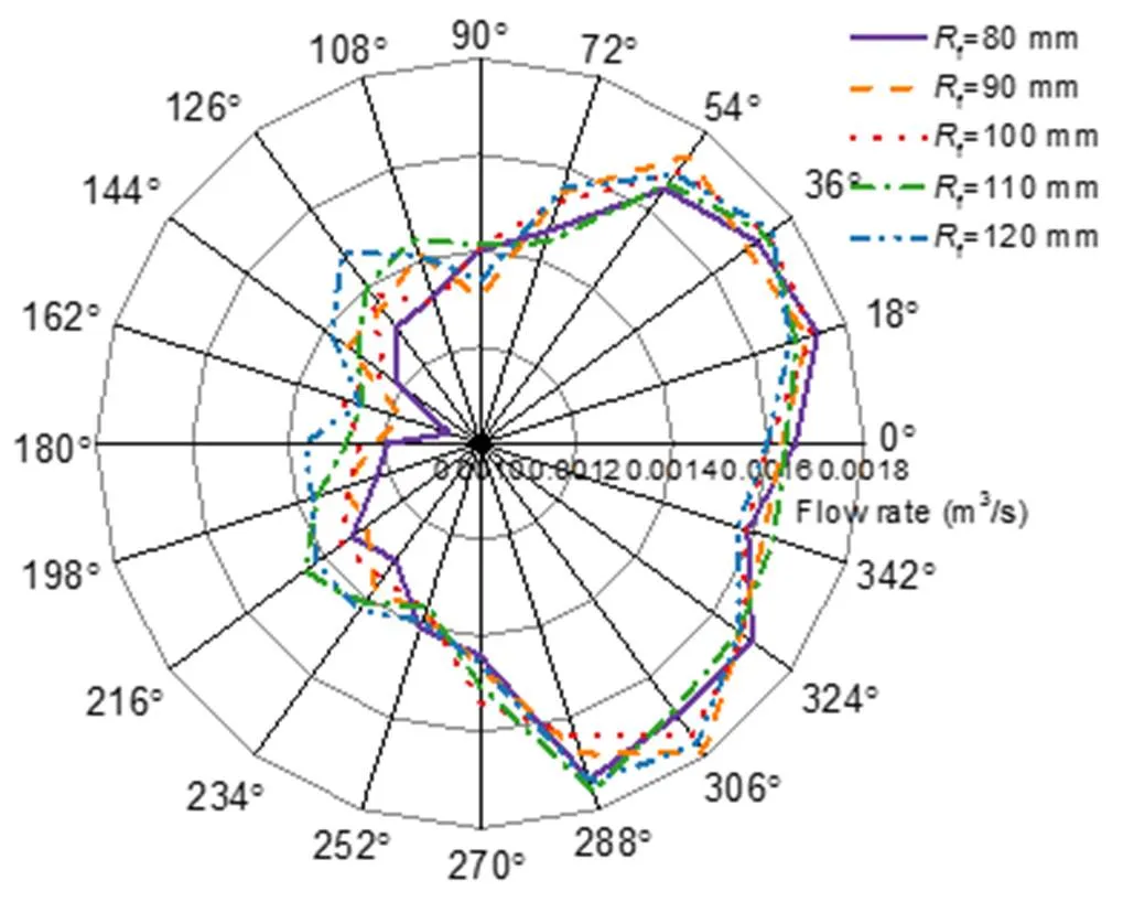
Fig. 8 Flow rate distribution in all directions near the bottom of the valve core
Table 3 shows the maximum pressure on the bottom of the valve core and its position corresponding to different values off, which reflects the offset degree of pressure distribution on the bottom of the valve core to a certain extent. The position of the maximum pressure is far from the center, indicating that the offset degree of the bottom of the valve core is greater and the unbalance moment of the valve core is greater. With the increase off, the maximum pressures vary over a very small range, and are all slightly less than 0.25 MPa. However, the position where the maximum pressure occurs gradually approaches the bottom center of the valve core along the-axis. Asfincreases from 80 to 120 mm, the distance between the position of the maximum pressure and the center point also decreases from 5.88 to 3.60 mm. In other words, the offset degree of pressure distribution on the bottom of the valve core becomes smaller, and the unbalanced moment of the valve core is gradually reduced. This is essentially consistent with the changes in the above-mentioned flow rate distribution.
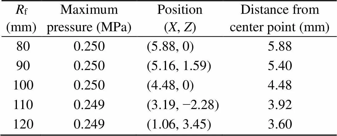
Table 3 Positions of maximum pressure under different Rf
In summary, with the increase off, the “low-speed zone” near the bottom of the valve core gradually approaches the center, the non-uniformity of flow rate distribution in all directions decreases, and the position where the maximum pressure appears gradually approaches the center. So the unbalanced moment on the bottom of the valve core decreases with the increase off, as shown in Fig. 9. Within the range off=80–120 mm, there is an obvious linear relationship between the magnitude of the unbalanced momentandf. The relationship between the unbalanced momentandfis presented as
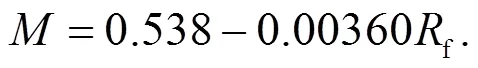
Moreover, all the data points are distributed within ±3% of the intercept.
In conclusion, the larger thefvalue is, the more symmetrical the fluid distribution is on the bottom of the valve core. Meanwhile, for a globe valve horizontally arranged, the valve volume increases with the increase off. Therefore, in the case meeting the requirements of the installation volume,fshould be selected as far as possible so as to reduce the unbalanced moment on the bottom of the valve core.
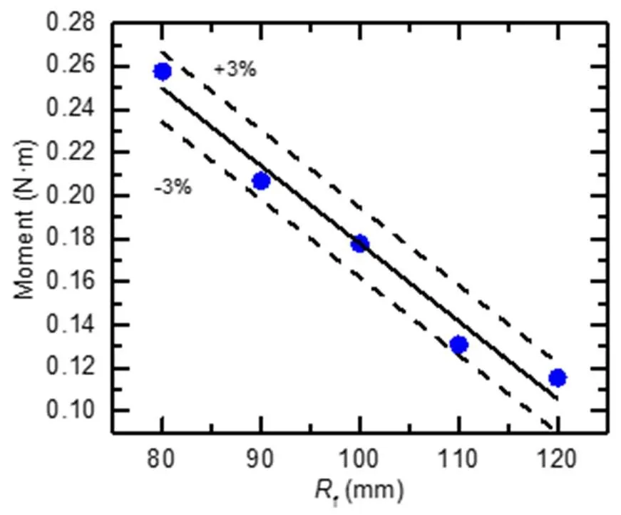
Fig. 9 Characteristic relationship between moment and Rf
3.3 Effects of the special-shaped pipe diameter
Fig. 10 displays the distributions of velocity and streamlines on the bottom of the valve core. The position of the “low-speed zone” on the bottom of the valve core can be viewed intuitively from Fig. 10. After the fluid impacts the valve core in the area with velocity less than 1 m/s, it flows out from all directions, and the flow velocity increases continuously. It can be seen that under the influence of the irregular inlet flow channel, the position of the fluid impacting the valve core can be offset, which makes the flow rate distribution in all directions unbalanced, and eventually leads to the phenomenon of unbalanced pressure on the bottom of the valve core. The greater the flow rate, the greater the moment on the bottom center of the valve core, as shown in Fig. 11. Similarly, to the flow rate distribution, the imbalance of the moment distribution is mainly manifested along the-axis. In the positive direction of the-axis, that is, on the side near the outlet direction, the moment is obviously larger than that on the other side. In the-axis direction, the flow rate and the moment are symmetrically distributed.
The outlet flow rate, the pressure difference, and the moment to the-axis and the-axis on the bottom of the valve core under differentare shown in Table 4. Compared with the moment about the-axis, the moment about the-axis is smaller. Moreover, the change rate of the-axis moment is small, and there is no definite change rule.mainly affects the outlet flow rate. With the increase of, the radial flow area between the valve core and the valve body increases. The flow resistance of the valve is reduced accordingly, which leads to a decrease in the pressure drop and an increase in the flow rate. Therefore, the resultant moment on the bottom of the valve core to the-axis increases accordingly. Whenchanges from 110 to 150 mm, the change rate of flow rate is 12.6%, and the moment about the-axis increases from 0.124 to 0.253 N·m.
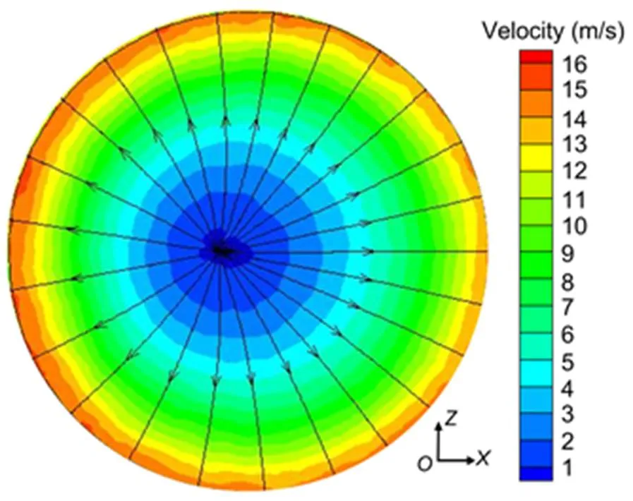
Fig. 10 Velocity and streamline distributions on the bottom of the valve core
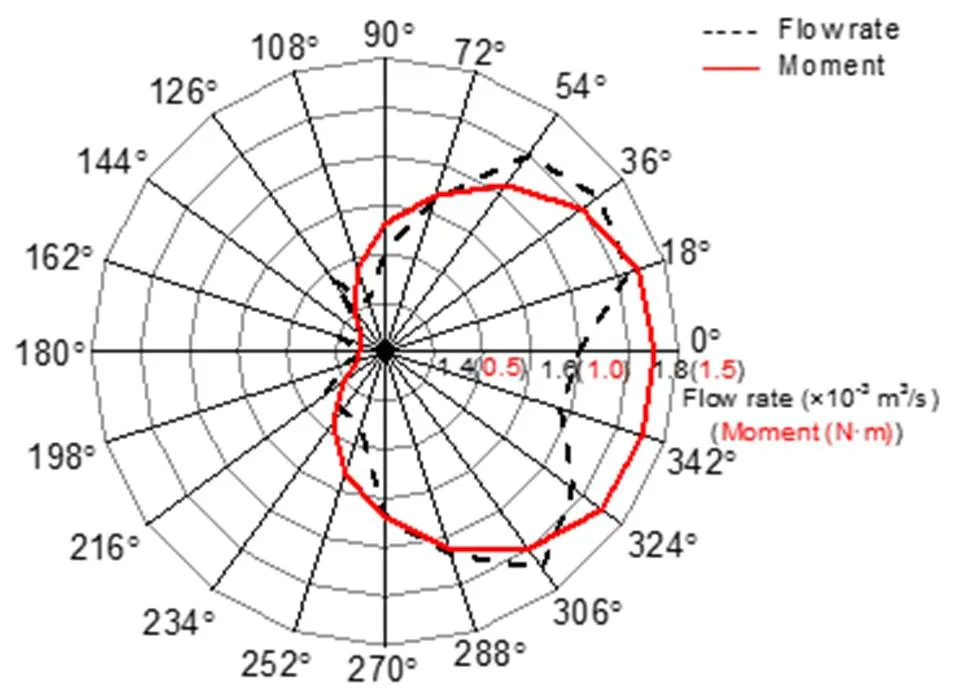
Fig. 11 Flow rate and moment distributions in all directions
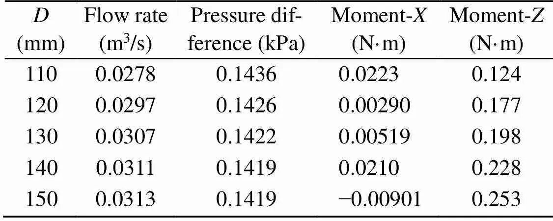
Table 4 Outlet flow rate, pressure difference, and moment on the bottom of the valve core under different D
Fig. 12 presents the pressure distribution on the symmetrical surface of the models with different. As shown in Fig. 12, when the fluid flows through the gap between the valve core and the valve seat, there is a very obvious pressure drop. The pressure on the lower surface of the bottom of the valve core decreases along the radial direction, while the pressure on the upper surface of the bottom of the valve core is well-distributed and the pressure is low. That is also the reason that the pressure on the upper surface of the bottom of the valve core is ignored in this study. With the increase of, the pressure between the valve core and the valve body gradually decreases, as shown in the rectangular box in Fig. 12. This is due to the increase of the radial flow area. After the fluid flows through the gap between the valve core and the valve seat, the flow in the radial direction is stronger. However,has little influence on the pressure distribution on the lower surface of the bottom of the valve core.
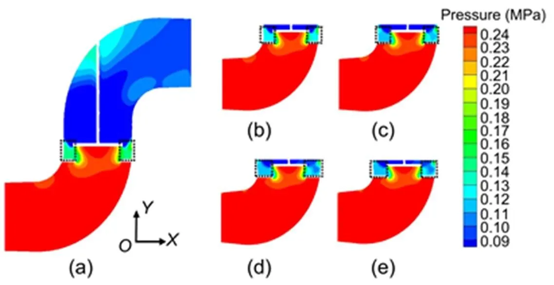
Fig. 12 Pressure profiles on the symmetry plane
(a)=110 mm; (b)=120 mm; (c)=130 mm; (d)=140 mm; (e)=150 mm
3.4 Effects of the valve core height
Different values ofrepresent different valve openings, and the valve opening determines the flow rate by changing the flow area in a circumferential direction. With the increase in, the flow rate and the pressure distribution on the bottom of the valve core both change. Assuming the area of each node is 1×10⁻⁶m2, the moment of each node about the bottom center of the valve core can be obtained according to the pressure and position information about the node. Fig. 13 shows the moment distribution on the bottom of the valve core. The forces acting on the points near the center of the valve core bottom have a short moment arm, and thus the moment within a radius of 10 mm is relatively small. The maximum moment is obtained between the radii of 20 and 30 mm. Compared with Figs. 13a–13c, with the increase of, the unbalance phenomenon becomes more obvious. As shown in Fig. 13, the moments in the sector areas formed by virtual coils are all less than 6.40×10⁻³N·m. When=20 mm, the angle of the sector area is about 40°. When=40 mm, the angle of the sector area increases to about 175° and when=60 mm, the angle of the sector area reaches 195°. Moreover, the sector areas are always located on the negative-axis, which means the moment of the positive-axis is obviously greater than that of the negative-axis. This makes the valve core trend to turn around the-axis. In the actual valve structure that trend will cause the valve core to squeeze the surrounding sealing elements and thereby affect the sealing performance of the valve.
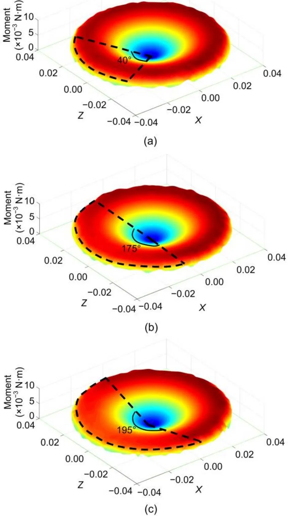
Fig. 13 Moment distribution at the bottom of the valve core: (a) H=20 mm; (b) H=40 mm; (c) H=60 mm
The flow rate and the moment on the bottom of the valve core under different values ofare shown in Table 5. With the increase of, the opening of the valve and the outlet flow rate both increase, which results in the increase of the unbalanced moment on the bottom of the valve core.is the decisive factor of the outlet flow rate, so with the increase offrom 15 to 70 mm, the change of outlet flow rate is more significant, increasing by 34.5%. The resultant moment of the bottom of the valve core is also changed greatly from 0.0551 to 1.220 N·m.
It can be seen from Table 5 that there is a certain non-linear relationship between the moment and the flow rate. It is assumed that the flow rate is an independent variableand the moment is a dependent variable. The relationship betweenandis assumed as follows:
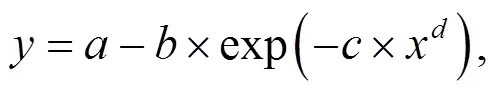
where,,, andare the coefficients to be solved in the assumed relation.
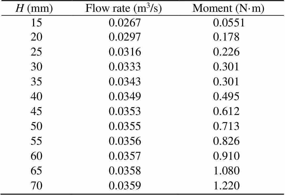
Table 5 Outlet flow rate and total moment on the bottom of the valve core under different H
The existing data are utilized to fit the non-linear formula based on different optimization algorithms. The fitting results are presented in Table 6. The formula obtained by the universal global optimization (UGO) algorithm has the smallest root mean square error (RMSE), the smallest sum of squares of residuals (SSE), and the largest correlation coefficient (), compared with the Quasi-Newton (BFGS) algorithm and the simplex method (SM) algorithm. Combining the above three factors, the formula obtained by the UGO algorithm is chosen as the optimal solution. Therefore, the moment and the flow rate are related by
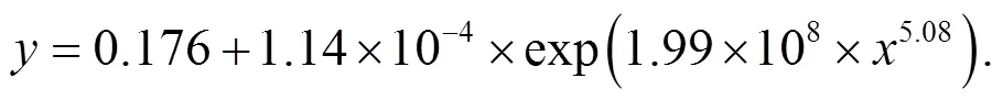
Fig. 14 shows the variation classification of the moment when the flow rate changes from 0 to 0.040 m3/s according to Eq. (7). According to Fig. 14, the variation classification of moment with the flow rate can be roughly divided into three stages. The first stage is basically unchanged and the flow rate range is 0–0.030 m3/s. In this stage, because the coefficient c before the xd term is small, the influence of x on y is small. The constant term in the functional relationship plays a leading role, so that the change of y is not obvious. The second stage is a stable growth stage, and the flow rate range is 0.030–0.035 m3/s. At this stage, xd reaches a large enough value, and the exponential term begins to have a visible effect on y. The third stage is the exponential growth stage, and the flow rate is more than 0.035 m3/s. When x reaches a large enough value, the exponential term plays a dominant role in the functional relationship between x and y, and y increases exponentially with the change in x. Therefore, in practical applications, the flow rate should be kept within the range of 0–0.030 m3/s as far as possible, and the flow rate should always be lower than 0.035 m3/s.
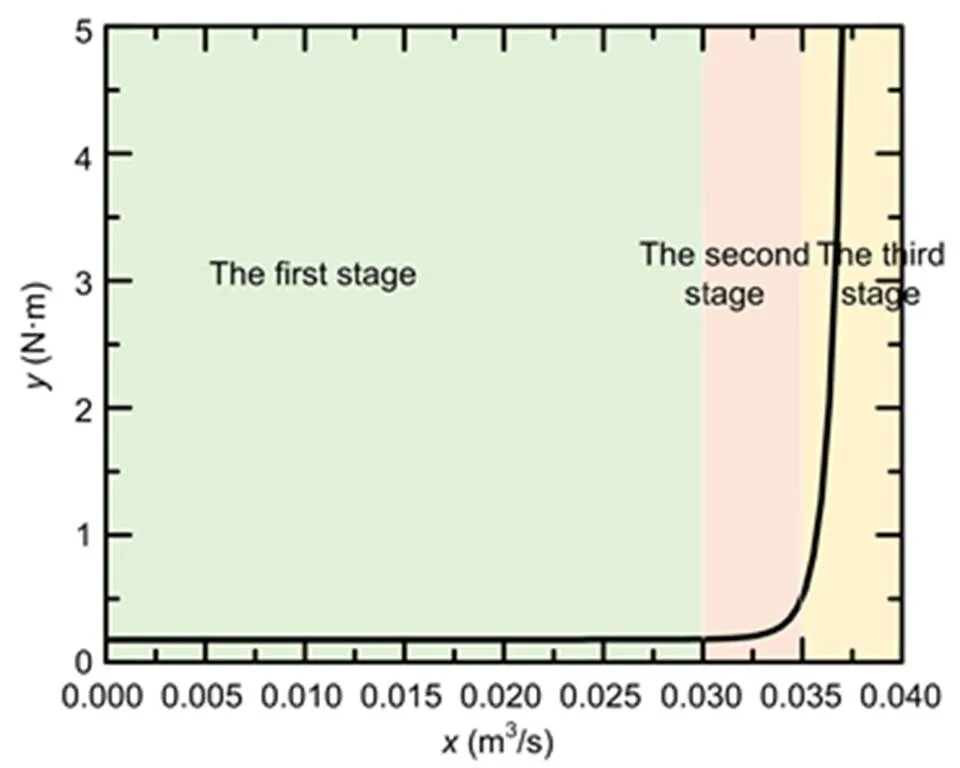
Fig. 14 Variation classification of moment with a flow rate based on Eq. (7)
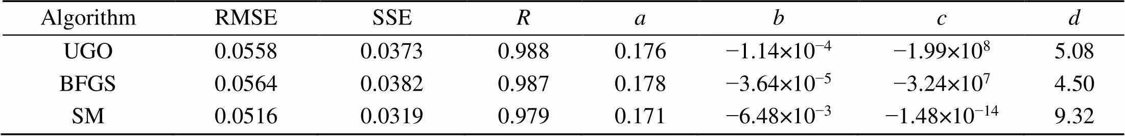
Table 6 Main parameters information on Eq. (6) under different optimization algorithms
4 Conclusions
To explore the effects of characteristic geometrical parameters on the unbalanced moment of a piston type valve core, a simplified model of a piston type globe valve is established. The numerical simulation results of the simplified model are verified by comparing their results with those reported in the literature. The flow characteristics and moment characteristics of the simplified model are analyzed under different inlet channel bending radii, different diameters of special-shaped pipe, and different valve core heights. The effects of the three characteristic parameters on the unbalanced moment of the piston type valve core are obtained.
With the increase of the bending radius of the inlet flow channel, the unbalanced moment on the bottom of the valve core decreases gradually. In practical applications, the unbalance moment can be reduced by appropriately increasing the bending radius of the valve inlet channel. In addition, the correlation between the unbalanced moment and the bending radius of the inlet flow channel is obtained in the range of 80–120 mm for the bending radius of the inlet flow channel. With the increase of the diameter of the specially-shaped pipe, the unbalanced moment on the bottom of the valve core increases slightly. In the design of the valve, the impact of the diameter of the specially-shaped pipe on the unbalanced moment can be ignored, and according to the working condition the appropriate diameter can be selected. The height of the valve core represents the opening of the valve and is the main influencing factor of the outlet flow rate. The larger the height of the valve core, the greater the outlet flow rate, which aggravates the unbalance of the moment distribution on the bottom of the valve core. The functional relationship between the unbalanced moment and the flow rate is obtained, and when the flow rate is larger than 0.035 m3/s, the change of the unbalanced moment becomes more intense and enters an exponential growth stage.
Contributors
Jin-yuan QIAN designed the research. Jin-yuan QIAN and Cong-wei HOU processed the corresponding data. Jin-yuan QIAN and Juan MU wrote the first draft of the manuscript. Zhi-jiang JIN helped to organize the manuscript. Juan MU revised and edited the final version.
Conflict of interest
Jin-yuan QIAN, Juan MU, Cong-wei HOU, and Zhi-jiang JIN declare that they have no conflict of interest.
Amirante R, Catalano LA, Poloni C, et al., 2014. Fluid-dynamic design optimization of hydraulic proportional directional valves., 46(10): 1295-1314. https://doi.org/10.1080/0305215X.2013.836638
Amirante R, Distaso E, Tamburrano P, 2016. Sliding spool design for reducing the actuation forces in direct operated proportional directional valves: experimental validation., 119:399-410. https://doi.org/10.1016/j.enconman.2016.04.068
Frosina E, Senatore A, Buono D, et al., 2016. A mathematical model to analyze the torque caused by fluid–solid interaction on a hydraulic valve., 138(6):061103. https://doi.org/10.1115/1.4032295
Frosina E, Senatore A, Buono D, et al., 2017. A modeling approach to study the fluid-dynamic forces acting on the spool of a flow control valve., 139(1):011103. https://doi.org/10.1115/1.4034418
Han MX, Liu YS, Wu DF, et al., 2017. A numerical investigation in characteristics of flow force under cavitation state inside the water hydraulic poppet valves., 111:1-16. https://doi.org/10.1016/j.ijheatmasstransfer.2017.03.100
Han MX, Liu YS, Wu DF, et al., 2018. Numerical analysis and optimisation of the flow forces in a water hydraulic proportional cartridge valve for injection system., 6:10392-10401. https://doi.org/10.1109/ACCESS.2018.2805684
Hou CW, Mu J, Li WQ, et al., 2019. Transient simulation on unbalanced torque of piston type valve cores during dynamic motion. Proceedings of the ASME-JSME-KSME 8th Joint Fluids Engineering Conference, No. V03AT03A018. https://doi.org/10.1115/AJKFluids2019-4733
Jin ZJ, Qiu C, Jiang CH, et al., 2020. Effect of valve core shapes on cavitation flow through a sleeve regulating valve., 21(1):1-14. https://doi.org/10.1631/jzus.A1900528
Kourakos V, Rambaud P, Buchlin JM, et al., 2013. Flowforce in a safety relief valve under incompressible, compressible, and two-phase flow conditions (PVP-2011-57896)., 135(1):011305. https://doi.org/10.1115/1.4006904
Lin Z, Wang HJ, Shang ZH, et al., 2015. Effect of cone angle on the hydraulic characteristics of globe control valve., 28(3):641- 648. https://doi.org/10.3901/CJME.2015.0313.030
Lisowski E, Filo G, Rajda J, 2018. Analysis of flow forces in the initial phase of throttle gap opening in a proportional control valve., 59:157-167. https://doi.org/10.1016/j.flowmeasinst.2017.12.011
Manring ND, Zhang SS, 2012. Pressure transient flow forces for hydraulic spool valves., 134(3):034501. https://doi.org/10.1115/1.4005506
Nguyen QK, Jung KH, Lee GN, et al., 2020. Experimental study on pressure distribution and flow coefficient of globe valve., 8(7):875. https://doi.org/10.3390/pr8070875
Qian JY, Liu BZ, Lei LN, et al., 2016a. Effects of orifice on pressure difference in pilot-control globe valve by experimental and numerical methods., 41(41):18562-18570. https://doi.org/10.1016/j.ijhydene.2016.08.070
Qian JY, Liu BZ, Jin ZJ, et al., 2016b. Numerical analysis of flow and cavitation characteristics in a pilot-control globe valve with different valve core displacements., 17(1):54-64. https://doi.org/10.1631/jzus.A1500228
Simic M, Herakovic N, 2015. Reduction of the flow forces in a small hydraulic seat valve as alternative approach to improve the valve characteristics., 89:708-718. https://doi.org/10.1016/j.enconman.2014.10.037
Wang H, Quan L, Huang JH, et al., 2019. Reduction of steady flow torques in a single-stage rotary servo valve., 233(4): 718-727. https://doi.org/10.1177/0954408918793402
Wang HH, Xu H, Zhang YH, et al., 2019. Design of a bio-inspired anti-erosion structure for a water hydraulic valve core: an experimental study., 4(3):63. https://doi.org/10.3390/biomimetics4030063
Wang YP, Zhu CN, Zhang G, et al., 2020. Numerical analysis to the effect of guiding plate on flow characteristics in a ball valve., 8(1):69.https://doi.org/10.3390/pr8010069
Zhang JH, Wang D, Xu B, et al., 2018. Experimental and numerical investigation of flow forces in a seat valve using a damping sleeve with orifices., 19(6):417-430. https://doi.org/10.1631/jzus.A1700164
Zhao JH, Zhou SL, Lu XH, et al., 2015. Numerical simulation and experimental study of heat-fluid-solid coupling of double flapper-nozzle servo valve., 28(5):1030-1038. https://doi.org/10.3901/CJME.2015.0417.045
https://doi.org/10.1631/jzus.A2000582
TH136
*Project supported by the National Natural Science Foundation of China (No. 51805470), the Zhejiang Provincial Key Research & Development Project (No. 2019C01025), and the Youth Funds of the State Key Laboratory of Fluid Power and Mechatronic Systems (Zhejiang University) (No. SKLoFP-QN-1801), China
Dec. 6, 2020;
Jan. 27, 2021;
Mar. 18, 2021