Consensus of multi-vehicle cooperative attack with stochastic multi-hop time-varying delay and actuator fault
CAI Guangbin, ZHAO Yushan, ZHAO Yang, and HU Changhua
1. College of Missile Engineering, Rocket Force University of Engineering, Xi’an 710025, China;2. School of Astronautics, Northwestern Polytechnical University, Xi’an 710072, China
Abstract: A consensus-distributed fault-tolerant (CDFT) control law is proposed for a class of leader-following multi-vehicle cooperative attack (MVCA) systems in this paper. In particular, the switching communication topologies, stochastic multi-hop timevarying delays, and actuator faults are considered, which may lead to system performance degradation or on certain occasions even cause system instability. Firstly, the estimator of actuator faults for the following vehicle is designed to identify the actuator faults under a fixed topology. Then the CDFT control protocol and trajectory following error are derived by the relevant content of Lyapunov stability theory, the graph theory, and the matrix theory. The CDFT control protocol is proposed in the same manner, where a more realistic scenario is considered, in which the maximum trajectory following error and information on the switching topologies during the cooperative attack are available. Finally, numerical simulation are carried out to indicate that the proposed distributed fault-tolerant (DFT) control law is effective.
Keywords: leader-following multi-vehicle cooperative attack(MVCA), switching topology, fault-tolerant control, stochastic multi-hop time-varying delay, stochastic actuator fault.
1. Introduction
At present, countries with considerable military might be attempting to enhance the capability of air defense systems further, thereby significantly increasing the possibility of intercepting a single vehicle and preventing the vehicle from achieving attack tasks. The concept of multivehicle cooperative attack (MVCA) has been proposed herein to complete the attack tasks more effectively.Clearly, the MVCA system will undergo further developments because of the various tactical formations, lower flight cost, and increased vehicles’ number [1-8].
In fact, vehicles can be treated as multi-agent (MA)nodes, because the relative distance among vehicles during a cooperative attack is large. Therefore, the consensus theory for multi-agents can be used in such systems[6-8]. Different types of time delays and actuator faults during cooperative attacks have been investigated. For example, Li et al. [9] studied a distributed optimization problem associated with a time-varying MA network considering the network delay, in which each agent has an influence on its convex objective function (COF), and the sum of the COF can be minimized cooperatively. On the basis of the mirror descent method, a distributed method was developed by exploring the delayed information of gradient. Moreover, an influence of the delayed gradient on the algorithm convergence was analyzed, and according to the network size, topology and delay parameter, an exact bound on the convergence rate was provided. Wang et al. [10] firstly converted the asymptotic consensus problem of the multi-missile cooperative guidance time into the asymptotic stability problem of different systems based on the graph theory. Thereafter,the asymptotic stability problem of different systems with a communication delay and topological uncertainty was analyzed based on the Lyapunov theorem. Furthermore,the above method was expanded to the situation under a switching topology for analyzing the guidance time consensus, and relatively sufficient conditions were obtained.Li et al. [11] studied the output consensus problem of linear discrete-time multi-agent systems (LDTMASs) considering heterogeneous dynamics as well as a communication delay (CD), and the networked predictive control scheme was introduced to make up for the network delay,for the sake of eliminating the worse influence of the CD.Moreover, a novel distributed protocol was given with the estimation of the agent outputs, and sufficient conditions of the output consensus were obtained for the LDTMAS with heterogeneous agents and a constant CD. The consensus of MA systems with constant communication time delays was investigated in [12-15]. Aimed at the consensus for the LDTMAS with CDs under directed topologies, Liu et al. [12] assumed that the CDs were constant but unknown, and based on the networked predictive control scheme, a consensus protocol to compensate for unknown delays was proposed. Wang et al. [13] studied the consensus among identical agents that were extremely coupled and easily divergent, through networks with a uniform constant CD, obtaining the delay tolerance’s upper bound, which explicitly relied on the network topology as well as agent dynamics in the case of directed networks. A method of controller design was proposed even when the network topology is not exactly known, resulting in achieving the MA consensus in a series of unknown networks for any delay satisfying the above bound for delay tolerance. It is clear that a higher delay tolerance is possible if the network topology can be known.Considering linear time-delay MA systems with a cooperative connected switching network, Lu et al. [14] studied the cooperative output regulation problem, and two lemmas were first established to provide the basis for solvingthe problem, following which, by means of the dynamic state as well as the dynamic measurement output feedback control protocol, the solution to the problem was presented. Based on the fact that the dynamic agent is easily divergent and the diagraph is not directed, Wang et al. [15] considered a consensus design problem for continuous-time first-order MA systems with a uniformly constant CD. The novel technique was that the historical input information was adopted in the protocol. In addition, the consensus of MA systems with time-varying CD has been studied in detail [16-19]. In directed networks,Xi et al. [16] studied the consensus problem considering arbitrary finite time-varying CD, under the fixed as well as switching topologies. Based on the feedback linearization and graph theory, the linear guidance law for each missile was obtained, and the consensus problem was successfully converted into the problem of judging the corresponding error system. Xia et al. [17] considered group consensus problems of continuous-time MA systems with time delays, in which the agent states were influenced by the information obtained from their neighbors at certain discrete instants. The case with a fixed topology and time-invariant delays, and the general case with switching topologies and time-varying delays, were respectively taken into account by using the graph theory and the nonnegative matrix theory, and several group consensus solutions were got in the cases, indicating that the agents in the non-zero in-degree groups (IDG) can be converged to the convex hull in the zero IDG. Aimed at the attitude dynamic tracking control for spacecraft formation considering non-measurable velocity, time-varying delays and switching topology, by a designed extended state observer, Yang et al. [18] developed a nonlinear attitude tracking control method for a spacecraft attitude model which was formulated by Euler-Lagrangian equations.
Qiao et al. [19] considered the delay-dependent coupling studied linear time-invariant MA consensus system,in which the homogeneous delays have effects on communication among agents. The coupling among the agents was designed as an explicit delay parameter, allowing for the couplings to adapt autonomously based on the delay values. The above works focused on single-hop time delays, while Ji et al. [20] investigated consensus problems of first-order MA systems with multiple time delays,which included three cases: discrete, continuous and a continuous system with a proportional derivative controller. In each case, the system contained communication and input time delays simultaneously. Moreover, it was concluded that the system convergence condition depends mainly on the input time delay of each agent and the adjacent weights, but has nothing to do with the communication delays among agents, regardless of whether the system is discrete or continuous.
MA systems with actuator faults have gained attention intensively. In [21], the current research progress in the fault-tolerant control problems and fault parameter identification problems of multi-agent systems was summarized in detail, and several future research directions in related fields were clearly stated. By constructing a highgain observer protocol and a cooperative fault-tolerant controller, an adaptive fault-tolerant control method is proposed for heterogeneous high-order cooperative MA systems, which can solve the problem of actuator faults and network disconnections [22]. Wang et. al. [23] investigated leader-following cooperative control with actuator faults for a multi-agent system with unknown nonlinearity. To detect actuator faults, a fault estimator was designed firstly. Secondly, a distributed fuzzy fault-tolerant control consensus algorithm was proposed, achieving effective tracking of the leader agents by the following agents. For a pure-feedback nonlinear MA system, the output-tracking consensus was well considered in [24],even though it had actuator faults. The consensus tracking of specific objects, for example, a power generation network, was solved based on distributed fault detection and fault-tolerant control. Experiment on the real power generation network verified the accuracy of the method[25].
Chen et. al. [26] investigated the fault-tolerant consensus in an MA system by a distributed adaptive protocol (DAP). They first proposed distributed adaptive online updating strategies for certain parameters by the partial information of the structure of network, and then, for the leaderless MA system, using parameters updated online, the DAP was improved to eliminate the fault and uncertainty effects. Meanwhile, the DAP gain was proposed, which resulted in a fully distributed continuous adaptive fault-tolerant consensus protocol design based on the local state information of neighboring agents. Similarly, a DFT leader-follower consensus protocol for the MA system was then presented.
According to the above mentioned research considering MA systems with time delays and actuator faults, it can be concluded that the consensus problem of MA systems with time delays and actuator faults simultaneously has not been considered deeply, that is, few works exist regarding the above interests. However, considering the problem whereby actuator faults and time delays in the leader-following MVCA system may lead to poorer performance of the consensus and the cooperative attack failure, it is significant to design a consensus algorithm that can eliminate the influence of time delays and actuator faults. Owing to the fact that the signal transmission power of vehicles in a multi-hop communication topology can be reduced, and the electromagnetic interference can be restrained effectively, the communication topology in this case is a multi-hop, as opposed to a singlehop, communication topology, which is of great practical significance for the valuable space and limited power capabilities of the vehicles.
Based on the above analysis, we make several efforts regarding the above problem. (i) For a fixed topology, we first design a fault estimator to detect the actuator faults,following which the consensus-distributed fault-tolerant(CDFT) control law is obtained after solving the Riccati equation and a linear matrix inequality (LMI) in the example that the communication topology of the following vehicles is already known, and the tracking error’s upper bound is obtained. On the basis of the Lyapunov stability theory, it proves that, when actuator faults cannot work properly, the following vehicles can maintain consensus with the leader vehicle effectively, and the tracking error’s upper bound is ultimately obtained. (ii) For switching topologies, we similarly design a fault estimator, and the CDFT control protocol and upper bound of the error during the cooperative attack are also obtained. (iii) Finally,the numerical simulation is conducted to verify the effectiveness of the CDFT control law proposed in this paper.
2. Preliminaries
A following vehicle with actuator faults can be modeled in the following:

where xixis the state of the following vehicle i in the direction of the x-axis belonging to the multi-vehicle common reference coordinate system (MVCRCS), uiis the control input actuating the following vehicle to track the state of the leader vehicle, and ωi(t)=[ωi,1(t),ωi,2(t),···,ωi,q(t)]∈Rqis the signal of the actuator fault.The state differential equation along the z-axis and y-axis for the following of the MVCRCS has a similar form of(1), and the states of these following vehicles can be influenced by their neighbor states as well as the leader through the interactive communication among these vehicles.
The leader vehicle can be modeled as

where x0xis the state of the leader vehicle with the number marked 0 in the direction of x-axis of the MVCRCS.It should be pointed out that the leader state will not be influenced by the following ones, and its velocity is a constant value. Furthermore, the state differential equation along the z-axis and y-axis for the leader vehicle of the MVCRCS has the same form of (2).
3. DFT control of MVCA system
3.1 Fault-tolerant cooperative control with multi-hop time delay under fixed topology
As we all know, the communication topologies between multiple vehicles are always fixed at any moment or in a very small period of time. Therefore, we first study the consensus fault-tolerant control of cooperative attack systems under the fixed topology. In this section, certain fundamental knowledge regarding the graph theory under a fixed communication topology is firstly provided.
The directed graph G={v,ε,Λ} describes the communication situations among the following vehicles. Here,v={n1,n2,···,nN}is the set of all following vehicles, where nirepresents the i th following vehicle;ε={(ni,nj)∈v×v}is the set of all edges, and (ni,nj)∈ε means that theith following vehicle can get the information from thejth following vehicle. Defining the adjacency set of nias Ni={j|(ni,nj)∈ε}, and Λ=[aij]∈RN×Nas the adjacency matrix, if (ni,nj)∈ε , aij=1; otherwise, aij=0. Assume that the vehicle is not connected to itself, that is, aii=0.Define the Laplacian matrix of the directed graph G as L=[lij]∈RN×N, and lij=−aijwhile i ≠j ; otherwise,lij=di, whereThus, L= D−Λ. The adjacency matrix of the leader vehicle is Λ0=diag(ai0), and if nihas the information transfer channel with the leader 0,ai0=1; otherwise, ai0=0.
For further analysis, the following assumptions and lemmas are required.
Assumption 1The communication topology among the following vehicles is a directed graph with a spanning tree, and the following vehicle with root node status can obtain the leader vehicle information. Thus, all of the following vehicles can obtain the information of the following vehicle with root node status.
Assumption 2In the communication topology, the pattern of the CD among adjacent vehicles is the same,while the CD among non-adjacent but reachable vehicles is the sum of the CDs on the path.
Lemma 1If there exists a spanning tree in the directed graph G, i.e., the following vehicle with root node status can obtain the leader vehicle information, let the symbol L be the Laplacian matrix of the graph G, Λ0be the adjacent matrix of the leader vehicle, andΛ=[aij]∈RN×Nbe the adjacent matrix of the following vehicles. Then, define
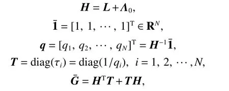
where H and T are both positive definite matrices.
Assumption 3The actuator fault satisfiesand i =1, 2, ···, N , k=1, 2, ···, q,ωi1M>0, ωi2M>0, and ‖·‖ denotes the 2-norm of a certain matrix.
Assumption 4(A,B) is controllable, i.e.,rank(B)=rank(B,E), then it can be found that there exists a matrix B∗∈Rm×nwhich satisfies (BB∗−In)E=0. 0 is an appropriate dimension matrix.
Lemma 2If P, Q, and R are all known matrices, then

is equivalent to

According to Assumption 1, the state error and adjacent cooperative error with a time delay are defined respectively as follows:
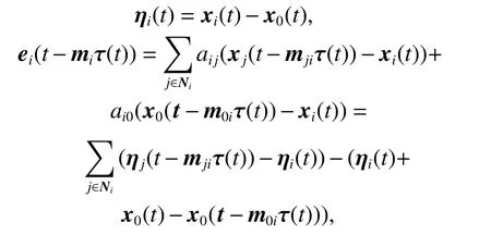
where j=1,2,···,N(j ≠i) is the notation of the following vehicles, m0iis the number of hops on the path from the leader to the ith following vehicle, mjiis the number of hops on the path from the jth following vehicle to the ith foll owing vehicle, τ(t) is the time-delay. mihas relevance with m0iand mji, i =1,2,···N , j=1,2,···,N, j ≠i .
The fault-tolerant controller of niis designed as follows:


where K ∈Rm×nis the gain matrix and c is the coupling parameter.
Select K=BTP , and P is a positive definite symmetric matrix which satisfies the Riccati equation:

where Q is a positive definite symmetric matrix as well.
Then, the dynamic equation about ηiwithout a time delay is
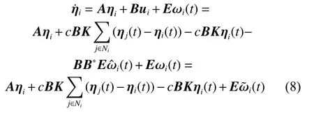
where i =1,2,···,N.
By means of the introduction ofand the Laplacian matrix L of graph G, we can obtain
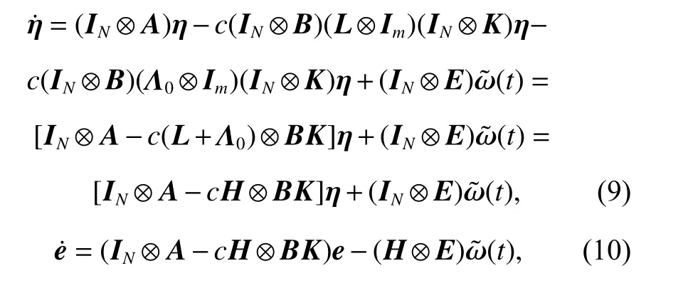
where ⊗ means the kronecker product, and INdenotes the N-dimensional unit matrix.
Thus, the state error dynamic equation and adjacent cooperative error dynamic equation of the error system with a time delay are

where

In the following theorem, we use the Lyapunov stability theory to conduct the stability analysis of the system.
Theorem 1Consider a leader-following MVCA system that is networked, if systems (1) and (2) satisfy Assumptions 1-4, and control law (5) is chosen. Then, all signals in the MVCA system with a stochastic single-hop time-varying delay τ(t) satisfyingj=0,1,2,···,N , i=1,2,···,N are ultimately uniformly bounded for a fixed topology G with a nonnegative weight, and the tracking error is limited as

Considering that there exists matrices Q, C and a parameter c which satisfies
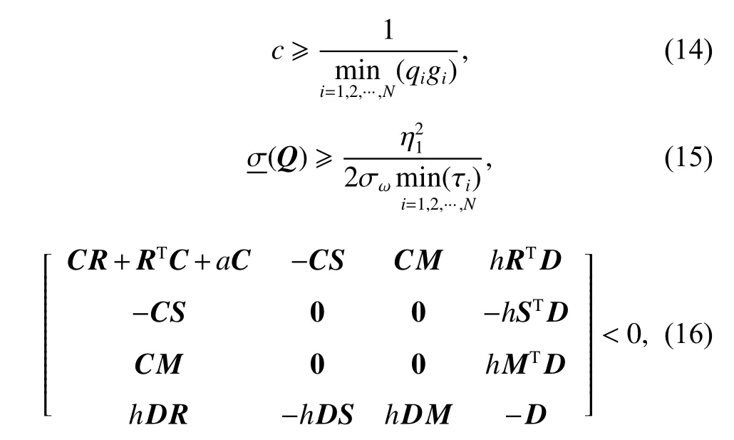

giis the ith eigenvalue ofγ >0, and qi,τihave been defined in Lemma 1,σω>0,means the maximum singular value of the matrix,and the adaptive rate ofis

where Γωi>0.
ProofLet n(t)=η(t −mτ(t)), ε =[ηTeT]T, then,

Let R=IN⊗A, S=cH ⊗BK , M=IN⊗E , then=Rη(t)−Sn(t)+
Consider the following Lyapunov-Krosovskii function:

where

Then, the derivation of this function along the direction of the error system is
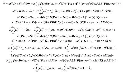
where

Then,

where
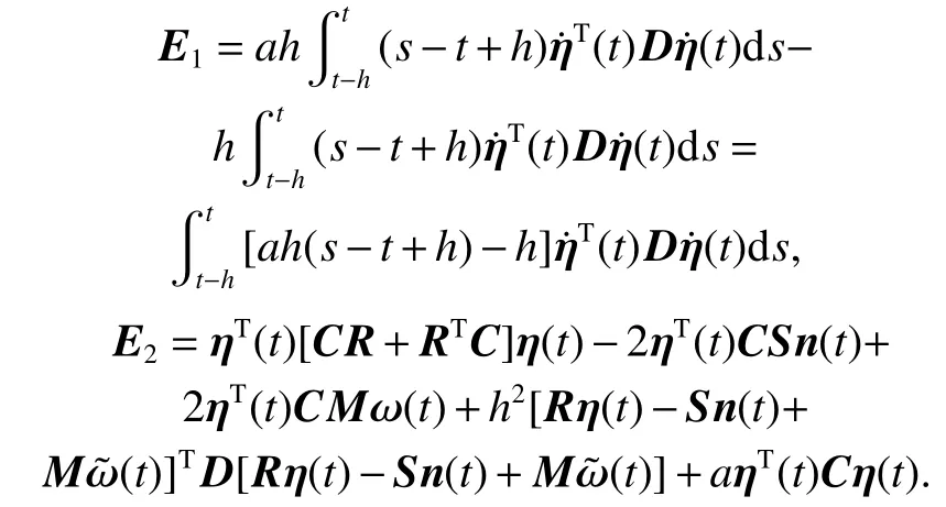
Rewrite E2as follows:
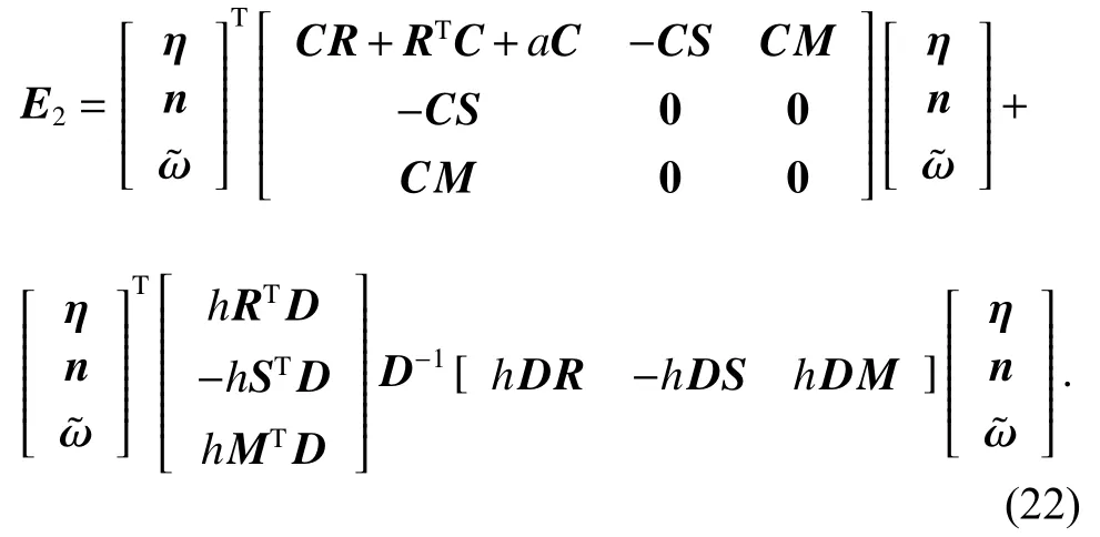
Define
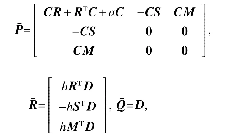
and if the positive definite symmetric matrix C satisfying:
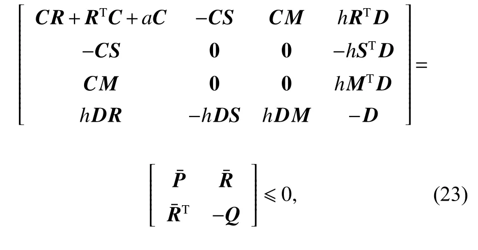
according to Lemma 2, (23) can be further converted to
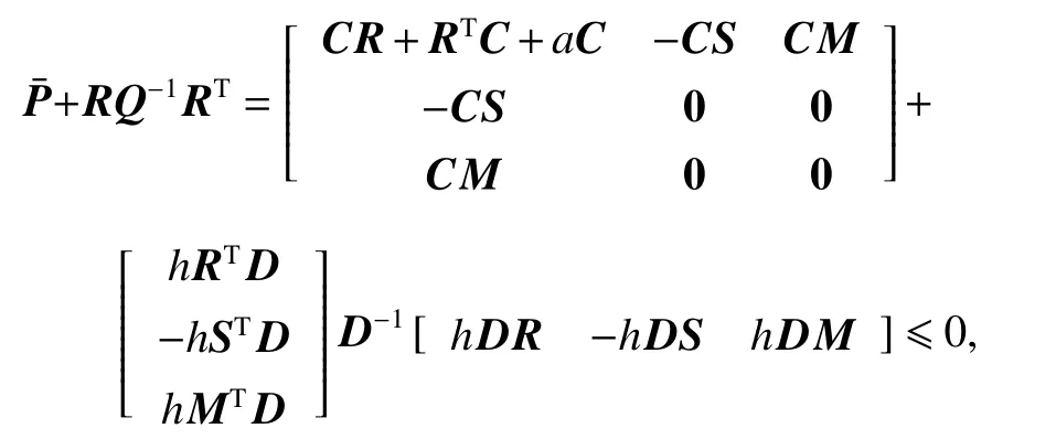
and obviously, E2≤0.
Because E1≤0 and

Because the second item of (24) is non-positive, one has

From (25), it is concluded that V1(t) exponentially converges to zero.

Derived from Lemma 1, the matrixcan be found to be a positive definite symmetric matrix, so we know that there must be a unit orthogonal matrix J satisfying that=diag(gi), where gi>0 and denotes the ith eigenvalue ofLetit has
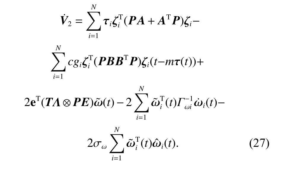
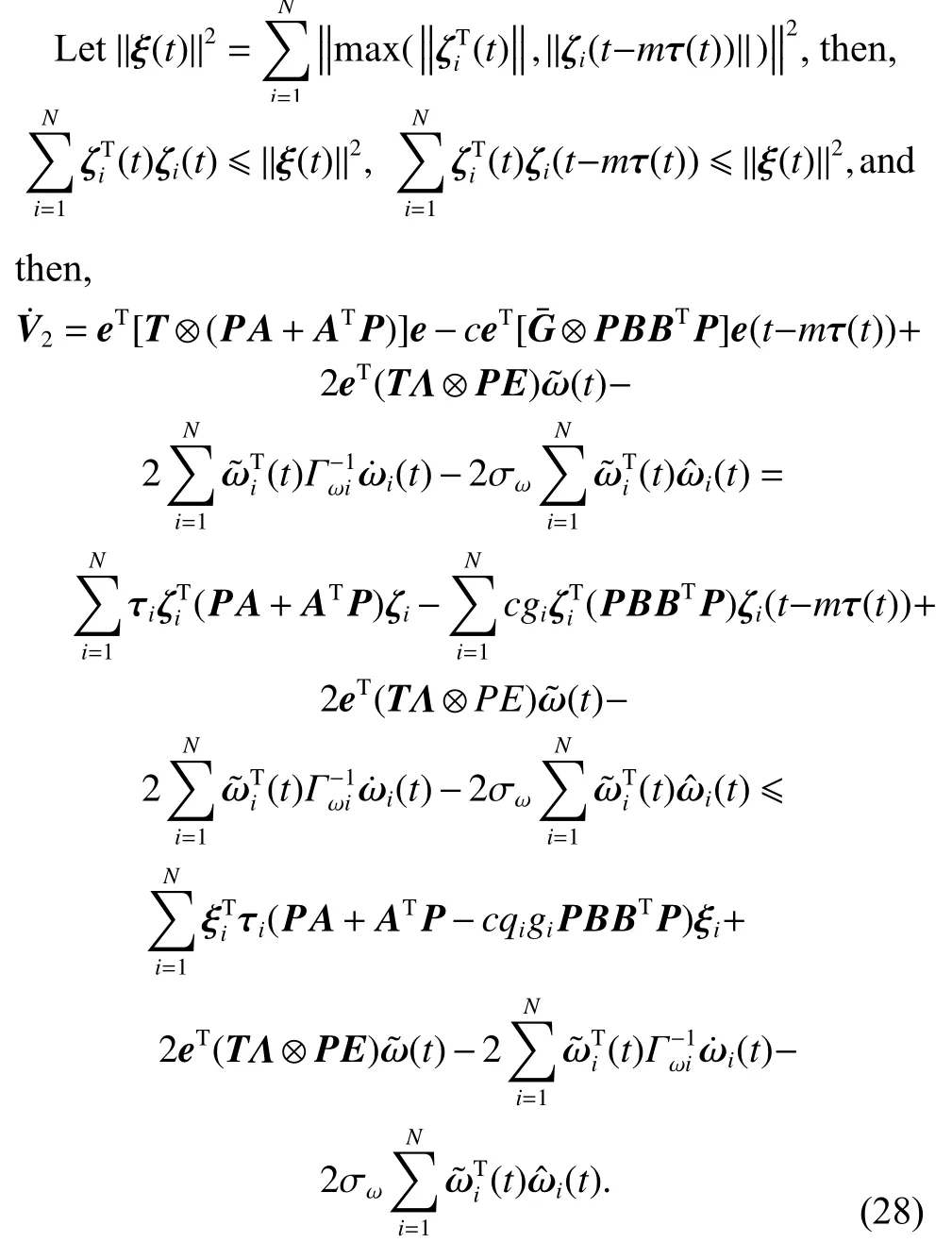
According to Assumption 3, we can obtain‖ω(t)‖≥
Substituting (7) and (14) into (28) yields
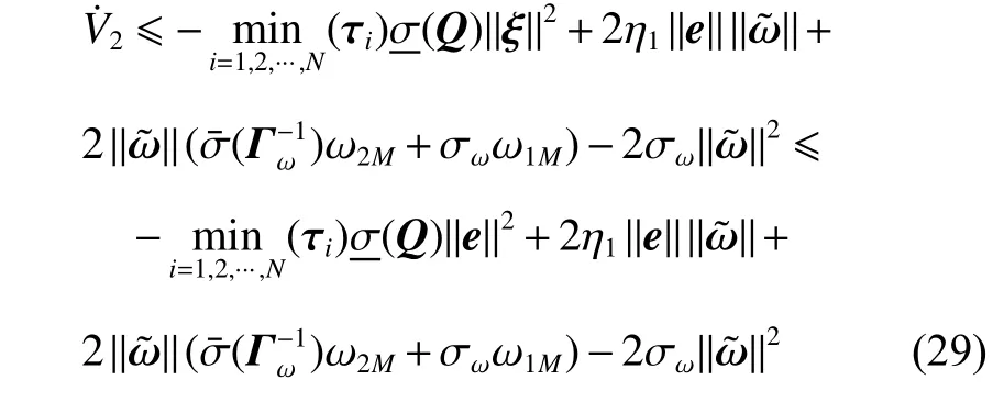
where Γω=diag(Γωi).
Let

where W is a symmetric matrix and W >0 derived from(15), and

Define

and the following formula can be derived from (21) and(30),

The following inequality can be derived from (31),


the upper bound of the following error can be obtained:

Synthesizing the results ofyields

and then,

Thus, all signals of the closed-loop system are ultimately uniformly bounded [27], and the state error meets the following limitation:

Remark 1Because the matrix E is unknown, the matrixin the proof may not be a square matrix. If it is not a square matrix, the appropriate dimension matrix 0 can be added to matricesand R, such thatis a square matrix.
3.2 Fault-tolerant cooperative control with multi-hop time delay under switching topology
During the combat process of the MVCA system, due to various factors, the communication topologies between the vehicles will change to some extent. It has been established that the interaction topology among the nodes of the multi-vehicle system is dynamic, i.e., a time-varying topology that is due to the impacts of some flight application scenario factors of MVCA systems; thus, the DFT control with switching interaction topologies grows in importance, and it is very significant to conduct the research on the leader-following MVCA system.
Next, we will provide some definitions and knowledge about the switching interaction topology based on the graph theory.
Definition 1Let κ(t):[0,∞)→h={1, 2, ···, N} be a switching signal, where N denotes the total number of topologies that possibly appear. The interaction topology remains unchanged among two adjacent switching moments. Let the interaction topology with a subscript k as the directed graph Gk={v,εk,Λk}. The interaction topology of the vehicle switches a limited number of moments during the full flight process of the MVCA system.
Assuming that the vehicles stay unchanged for existing switching topologies, and the symbol v in switching topologies has the same meaning in a fixed topology. Here,the ith following vehicle is denoted as ni,k, and εk={(ni,k,nj,k)∈v×v}is the graph edge in the interaction topology at moment k , and (ni,k,nj,k)∈ε shows the fact that ni,kcan get the information of nj,k.
Let the adjacent set of ni,kbe Ni,k={j|(ni,k,nj,k)∈ε},Λk=[aij,k]∈RN×Nis set to be the adjacent matrix. Set aii,k=0, and if (ni,k,nj,k)∈ε , aij,k=1; otherwise, aij,k=0.Let Lk=[lij,k]∈RN×Ndenotes the Laplacian matrix and define in-degree matrix as Dk=diag(di,k)N×Nof graph Gk.If i= j, lij,k=di,k; otherwise,Thus, Lk= Dk−Λk. The adjacent matrix of the leader at moment k is Λ0k=diag(ai0,k) , and if ni,kcan receive the leader information, then ai0,k=1; otherwise, ai0,k=0.
The assumptions and lemmas below are necessary for further analysis.
Assumption 5The differential equation of state for the leader with switching topologies has the same form when it is under a fixed topology.
Assumption 6All the interaction topologies existing among the following vehicles are directed graphs, and each of them has a spanning tree, moreover, a following vehicle with root node status can receive the leader vehicle state information. Thus, all of the following vehicles can get the information of the following vehicle with root node status.
Lemma 3If the directed graph Gkhas a spanning tree, and the symbol Lkdenotes the Laplacian matrix of Gk, the following vehicle with root node status can obtain the leader vehicle information, Λ0kmeans the adjacent matrix of the leader vehicle, and Λk=[aij,k]∈RN×Nrepresents the adjacent matrix of the following vehicles.Then, define
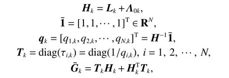
where Tk>0 and Hk>0, i.e., both of the two matrices are positive definite.
Assumption 7The actuator fault satisfies the inequalitywherei=1, 2, ···,N, r=1, 2, ···, q, ωi1M>0, ωi2M>0.
Now, we analyze the differential equations of state for the systems below:

where ωi,k(t)=[ωi1,k(t),ωi2,k(t),···,ωiq,k(t)]∈Rqis the actuator fault signal.
According to Assumption 1 and Assumption 5, the adjacent cooperative error with a time delay is defined as
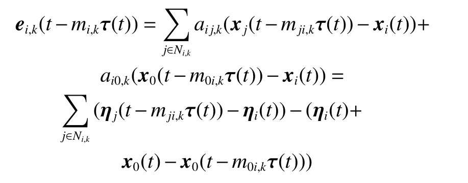
where j=1,2,···,N( j ≠i) is the notation of the following vehicles, m0i,kis the number of hops on the path from the leader to the ith following vehicle, mji,kis the number of hops on the path from the jth following vehicle to the ith following vehicle, and τ(t) is the time delay. Moreover,mi,kexhibits the relevance to m0i,kand mji,k, i=1,2,···N,and j=1,2,···,N, j ≠i.
The fault-tolerant controller of niis designed as


whereckis the coupling parameter, and Kk∈Rm×nis the gain matrix.
LetKk=BTPk, where Pkand Qkare both positive definite symmetric matrices which satisfy the Riccati equation as follows:

Then,the dynamic equation aboutwithout a time delay is
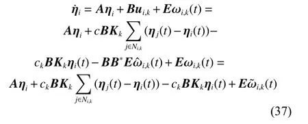
where i =1,2,···,N.
By means of the introduction ofand the Laplacian matrix Lkof graph Gk, we can obtain
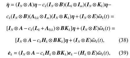
where Hk=Lk+Λ0,k.
Thus, the state error dynamic equation and adjacent cooperative error dynamic equation of the error system with a time delay are obtained respectively as follows:

where

Next, the following theorem is presented to analyze the system stability on the basis of the Lyapunov stability theory.
Theorem 2Consider a leader-following MVCA system that is networked with the control law (31), and multi-vehicle systems (2) and (30) satisfy Assumption 2 and Assumptions 4-7; then, all signals in the MVCA system with a stochastic single-hop time-varying delay τ(t) satisfyingj=0,1,2,···,N and i=1,2,···,N are ultimately uniformly bounded for switching topologies Gkwith a nonnegative weight, and the tracking error satisfies

If there exists a coupling parameter ck, a matrix Qksatisfying
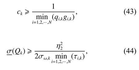
and a matrix Ck>0, such that
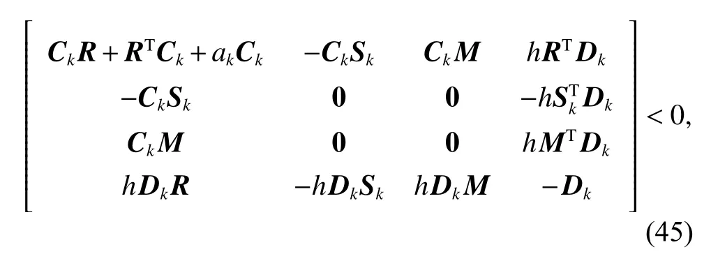
where symmetric matrix Dk>0 , R =IN⊗A, Sk=Hk⊗BKk,M=IN⊗E, akis a real number satisfying

gi,kis the ith eigenvalue of, γ >0, these symbolsqi,k,, τi,khave been defined in Lemma 3,η2=(PkE), σω,k>0 , and the adaptive rate ofis

where Γωi,k>0.
ProofLet nk(t)=η(t −mkτ(t)),then,

Let R =IN⊗A, Sk=ckHk⊗BKk, and M =IN⊗E, then
Consider the following Lyapunov-Krosovskii function:

where

Following the proof of the DFT design for the MVCA under a fixed topology, the following formulas can be obtained:
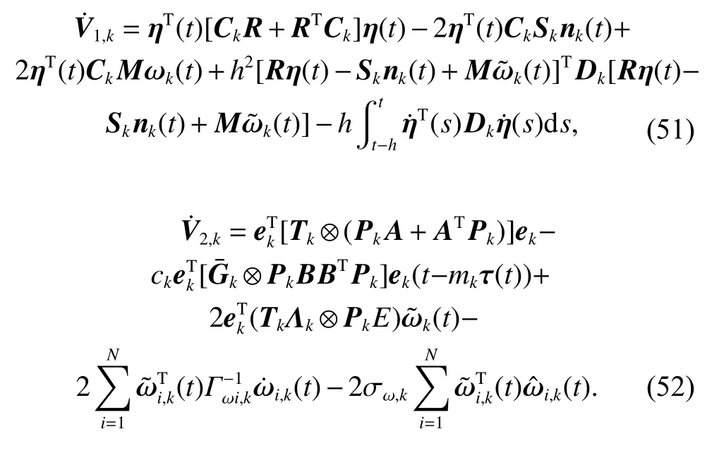
Similar to the process of the above proof under a fixed topology, synthesizing the results ofyields

thus,

Therefore, all signals of the closed-loop system are ultimately uniformly bounded [27] and the state error is obtained by

Thus, it can be obtained that the tracking error’s upper bound iswith switching topologies.
4. Numerical example
Consider an MVCA system with four second-order integrators, and the system contains a leader vehicle as well as three following vehicles [28,29]. The system matrices in(1), (2), and (33) are selected as follows:
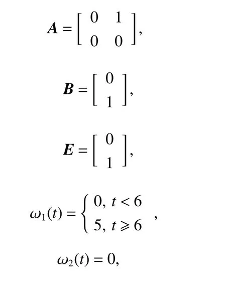

Fig. 1 shows interaction topologies between the leader vehicle and the following vehicles.

Fig. 1 Switching topologies
The stochastic single-hop time-varying delay is assumed to vary, as shown in Fig. 2.
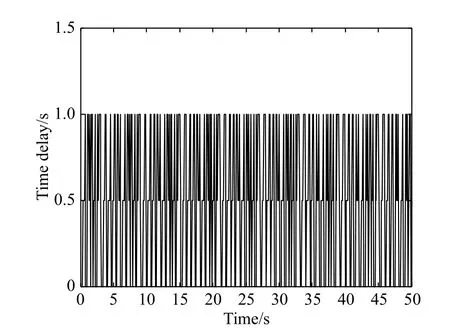
Fig. 2 Stochastic single-hop time-varying delay
The interaction topology is chosen to switch from topology 1 to topology 2 at the moment t=10 s, then switch from topology 2 to topology 3 at t =30 s.
The initial states of position and velocity for vehicles on each coordinate axis are respectively presented in Table 1.
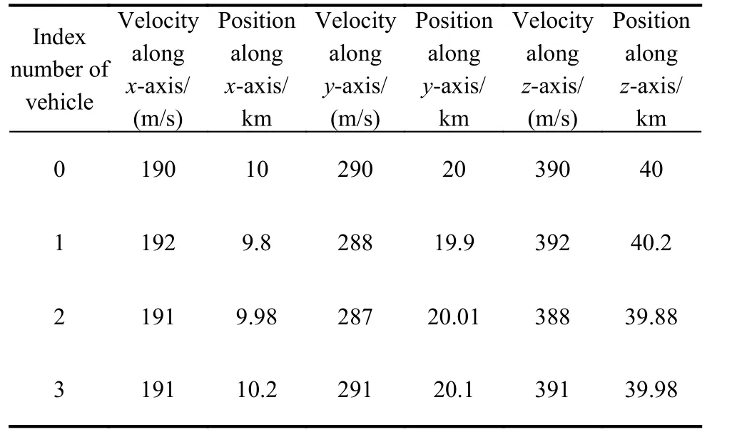
Table 1 Initial state of each vehicle
By solving (7) and (36), it can be obtained that
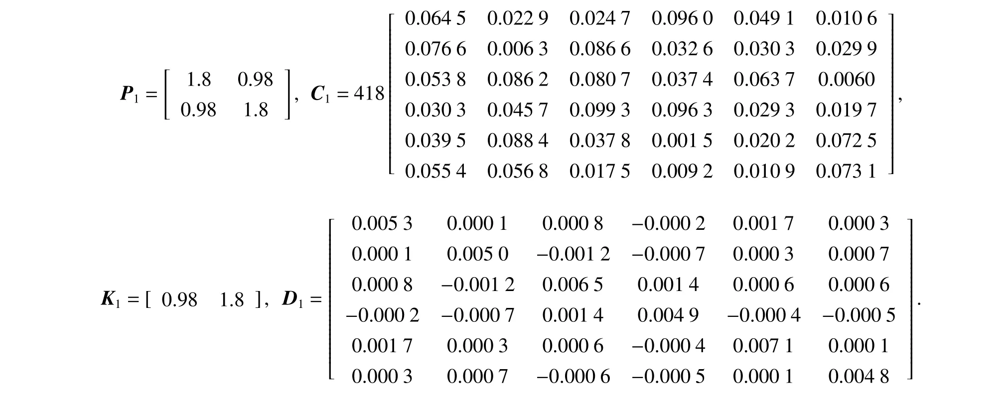
Using the same method, the other matrices can be obtained as follows:
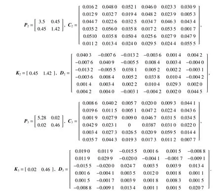
The main parameters are selected as follows: c1=2.7,c2=1.2, c3=1.3, a1=0.01, a2=0.1, a3=0.2, σω,1=1.927, σω,2=1.35, σω,3=2.58, Γω1,1=Γω1,2=Γω1,3=85,Γω2,1=Γω2,2=Γω2,3=81.025, Γω3,1=Γω3,2=Γω3,3=84.59,and h =3.5.
The results of simulation are presented in Figs. 3-14.
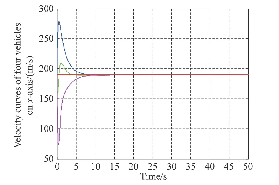
Fig. 3 Velocity states on x-axis
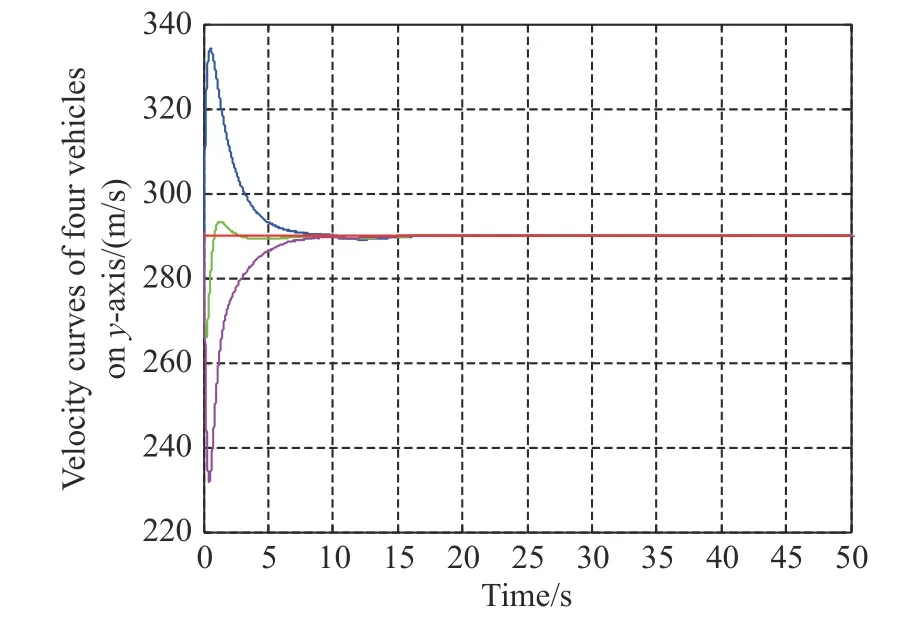
Fig. 4 Velocity states on y-axis
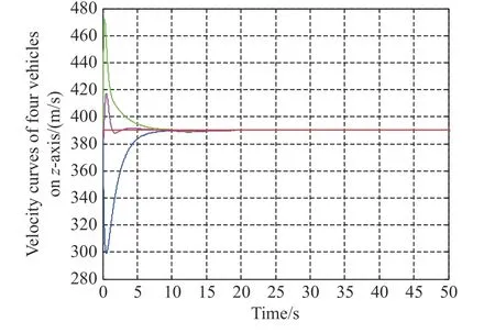
Fig. 5 Velocity states on z-axis
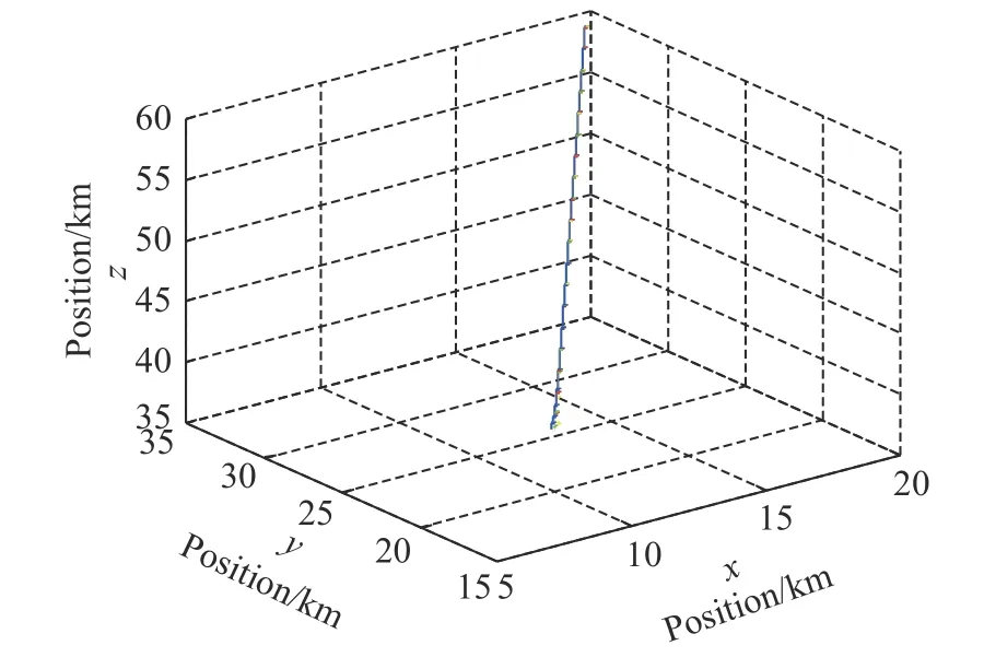
Fig. 6 Trajectories of four vehicles in 3-D space
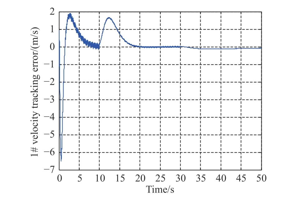
Fig. 7 Velocity tracking error between vehicle 1 and vehicle 0
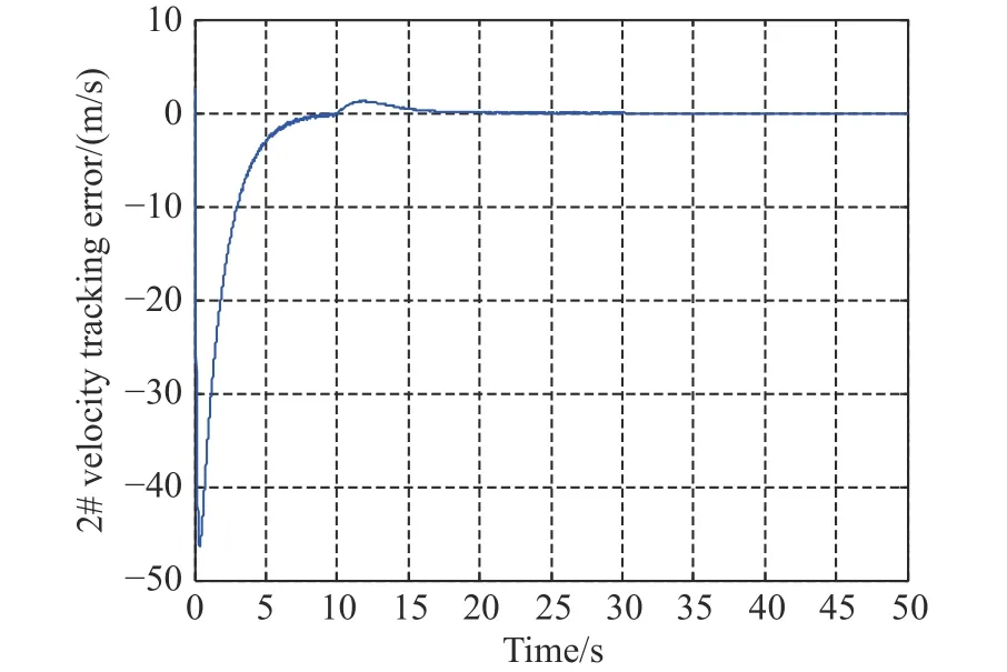
Fig. 8 Velocity tracking error between vehicle 2 and vehicle 0
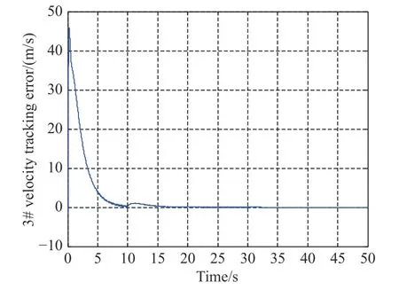
Fig. 9 Velocity tracking error between vehicle 3 and vehicle 0
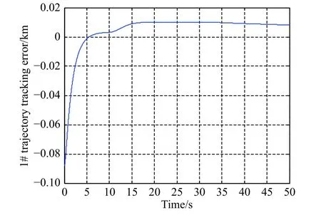
Fig. 10 Trajectory tracking error between vehicle 1 and vehicle 0
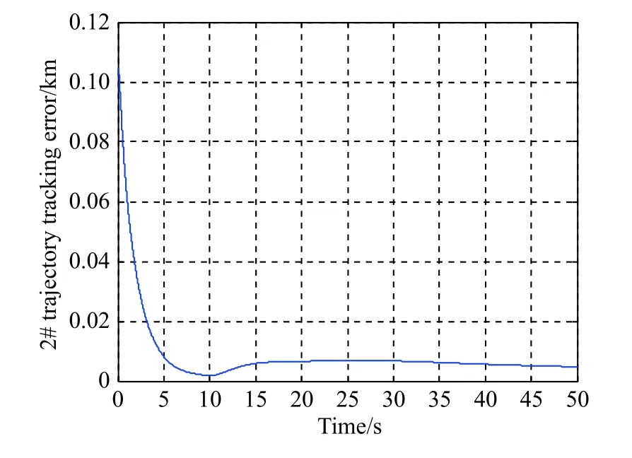
Fig. 11 Trajectory tracking error between vehicle 2 and vehicle 0
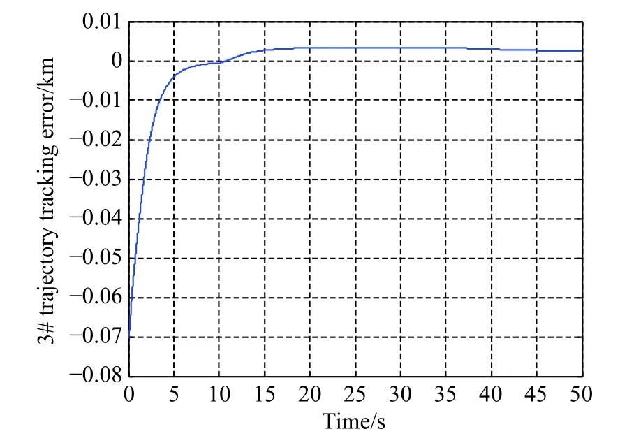
Fig. 12 Trajectory tracking error between vehicle 3 and vehicle 0
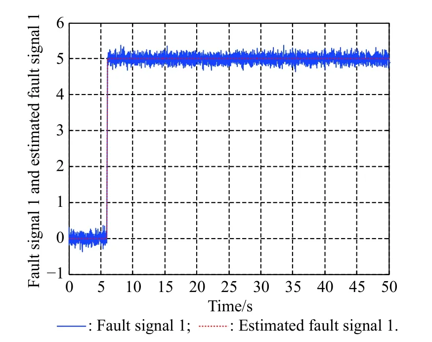
Fig. 13 Fault signal 1 and estimated fault signal 1
Figs. 3-5 show the velocity curves of the leader-following multi-vehicles along the x-axis, y-axis, and z-axis,respectively. In Figs. 3-5, the red line depicts the velocity of the leader along the x-axis of the MVCRCS, while the blue, green, and yellow lines represent the velocities of following vehicles 1, 2 and 3, respectively, along the xaxis of the MVCRCS. As can be seen from the three figures, despite the combined influence of the switched interaction topology twice, i.e., at the moment t=10 s and t=30 s , respectively, the actuator fault at t=6 s for vehicle 2 and at t=31 s for vehicle 3, and the stochastic multi-hop time-varying delays exist in the communication topologies, and the velocities of the three vehicles finally tend towards the velocity of the leader. In the beginning, the velocities of the following vehicles undergo significant changes, and following vehicle 1 reaches its maximum velocity along the x-axis at t =0.56 s, while following vehicle 2 and vehicle 3 reach their minimum velocities at t=0.19 s and t=0.46 s, respectively. It indicates that all of the following vehicles still fly along their own guidance laws at the beginning, while their flying parameters quickly tend towards the flying parameters of the leader vehicles once the cooperative guidance control law is added to the following vehicles. Finally, the cooperative attack system achieves the consensus of the velocity.
Fig. 6 depicts the trajectories of the leader and following ones, and it is obvious that the trajectories of the following ones finally track the trajectory of the leader. In Fig. 6, one can also see that the trajectories of the leader and following ones are ultimately parallel.
Figs. 7-9 are the speed tracking error curves between the following ones 1, 2, 3 and the leader vehicle 0. It can be seen from Figs. 7-9 that the speed tracking errors between the three following ones and the leader all eventually reach zero, which shows that all speeds of the following vehicles eventually approach the speed of the leader vehicle. In Figs. 7-9, the switching topology at 10 s has a significant impact on the tracking errors of the three following vehicles, especially for the following vehicle 1,but the three following vehicles are not affected by the above switching topologies and tend to be consistent. The effects of the actuator faults of the following vehicle 1 and vehicle 3, and the stochastic multi-hop time-varying delays existing in the communication topologies have almost disappeared, which highlights the effectiveness of the designed control law.
Figs. 10-12 are the tracking error curves of the trajectory distances of the three following vehicles and the leader vehicle, respectively. One can see from Figs. 10-12 that although affected by the switching topologies, stochastic multi-hop time-varying delays, and some actuator faults of the following vehicles, the trajectory distances between all the following vehicles and the leader vehicle gradually decrease to a reasonable range. The trajectory tracking errors in Figs. 10-12 do not finally converge to an absolute zero value, which also reflects the existence of the maximum tracking error in the above Theorem 2.
The results of the fault estimators are shown in Fig. 13 and Fig. 14, from which it can be seen that the designed fault estimator presented in this paper can effectively identify the system fault. These also explain the phenomenon that the effect of actuator failures in the speed curves, speed tracking error curves, and trajectory tracking error curves is almost zero, which highlights the effectiveness of the designed fault estimator.
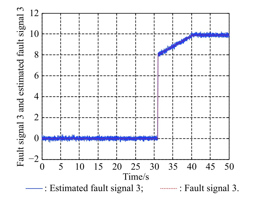
Fig. 14 Fault signal 3 and estimated fault signal 3
5. Conclusions
For tackling the problem that the switching communication topologies and stochastic multi-hop time-varying delays in the leader-following MVCA system, as well as stochastic actuator faults of the following ones, have a negative effect on the consensus performance or even destabilize the cooperative attack system, firstly an estimator for the following vehicle actuator fault is designed to identify actuator faults under a fixed topology. Secondly, the CDFT control law and tracking error are derived by the matrix theory, the graph theory and the Lyapunov stability theory, based on the fact that stochastic multihop time-varying delays in the cooperative attack system and actuator faults exist simultaneously under the fixed topology. By considering a practical application scenario under switching topologies, the CDFT control law is also derived by using a similar method in the same context under the fixed topology, and the maximum tracking error during the cooperative attack is provided and proven. The numerical simulation verifies that the CDFT control law is effective, and the related results in this paper provide a design method of the DFT control law on the basis of the simultaneous existence of stochastic multi-hop time-varying delays in the cooperative attack system and actuator faults.
 Journal of Systems Engineering and Electronics2021年1期
- Journal of Systems Engineering and Electronics的其它文章
- Unsplit-field higher-order nearly PML for arbitrary media in EM simulation
- A deep learning-based binocular perception system
- STAP method based on atomic norm minimization with array amplitude-phase error calibration
- Higher order implicit CNDG-PML algorithm for left-handed materials
- Fast and accurate covariance matrix reconstruction for adaptive beamforming using Gauss-Legendre quadrature
- Multiple interferences suppression with space-polarization null-decoupling for polarimetric array
