Multiple interferences suppression with space-polarization null-decoupling for polarimetric array
LU Yawei, MA Jiazhi, SHI Longfei, and QUAN Yuan
State Key Laboratory of Complex Electromagnetic Environmental Effects on Electronics and Information System,College of Electronic Science, National University of Defense Technology, Changsha 410073, China
Abstract: The adaptive digital beamforming technique in the space-polarization domain suppresses the interference with forming the coupling nulls of space and polarization domain.When there is the interference in mainlobe, it will cause serious mainlobe distortion, that the target detection suffers from. To overcome this problem and make radar cope with the complex multiple interferences scenarios, we propose a multiple mainlobe and/or sidelobe interferences suppression method for dual polarization array radar. Specifically, the proposed method consists of a signal preprocessing based on the proposed angle estimation with degree of polarization (DoP), and a filtering criterion based on the proposed linear constraint. The signal preprocessing provides the accurate estimated parameters of the interference, which contributes to the criterion for null-decoupling in the space-polarization domain of mainlobe. The proposed method can reduce the mainlobe distortion in the space-polarization domain while suppressing the multiple mainlobe and/or sidelobe interferences. The effectiveness of the proposed method is verified by simulations.
Keywords: multiple interferences suppression, dual polarization array radar, null-decoupling.
1. Introduction
In practical application scenarios, the mainlobe and sidelobe of radar are likely to be interfered by the barrage interferences at the same time. The multiple interferences are difficult to suppress especially when they are in the mainlobe. Because the target signal may be continuously covered in both time and frequency domains by barrage interferences. Radar needs to cope with multiple interferences suppression and maintain the ability of target detection. For the array radar, the methods of the interference suppression are very concerned by researchers.
In the space domain, mainlobe interferences suppression in adaptive digital beamforming (ADBF) will bring distortion in the mainlobe [1] and reduce the reception gain in the target direction [2,3]. Methods based on the block matrix and eigen-subspace preprocessing [4-8] are proposed to solve the problem of mainlobe distortion. However,when the target signal is closed to the mainlobe interference in the space domain, these methods will suppress both the mainlobe interference and the target signal. ADBF based on the covariance matrix reconstruction [9-11]and steering vector estimation [12,13] is proposed to suppress the multiple interferences. These methods get more accurate nulling position of interferences, but they are still unable to solve the problem of serious target energy loss under the multiple mainlobe interferences. In addition, these methods combined with subarray [14-16] can reduce the calculation amount of ADBF in practical application, but they still cannot solve the problems above.For the methods based on the blind source separation[17-20], the problem of amplitude and phase distortion of the target signal is inevitable, which leads to errors of the target angle measurement. Moreover, the separation effect will get worse when there are more than one Gaussian interference.
In the polarization domain, the development of polarization filtering contributes to the interference suppression[21-23]. The interference suppression polarization filter(ISPF) is based on the orthogonal projection [24-26].When the polarization of the target signal is orthogonal to that of the interference, these methods can achieve an effective impact on the interference suppression. An oblique projection polarization filter (OPPF) constructed from the signal ’s polarization subspaces was proposed in [27], which was still available without prior information of the interference. However, these methods are difficult to apply when there is more than one interference in the mainlobe.
In the multi-domain, we can get more characteristic difference between targets and the interference than that in each individual domain [28,29]. Thus, the effect of the interference suppression can be significantly improved. In[30], the method was based on the polarization array and generated adaptive nulls in the space-polarization domain to suppress the interference. A space-polarization-frequency domain collaborative filter based on the oblique projection was provided to recover the original target and suppressed the interference in [31]. However, the interference nulls in the space-polarization domain are generated with each other at the same time. Though the coupled nulls can make interference nulls deeper and suppress the interference more effectively, they can also aggravate the mainlobe distortion and lead to more target energy loss.
Since the performance of multiple interferences suppression in the multi-domain suffers from the coupled nulls in the mainlobe and insufficient information in a single domain, a multiple mainlobe and/or sidelobe interferences suppression method based on null-decoupling is proposed for dual polarization array radar in this paper.
The signal processing system is summarized in Fig. 1.In the signal preprocessing, we propose a searching algorithm based on degree of polarization (DoP) and a mainlobe interference cancellation method. Thus, the parameters of multiple mainlobe barrage interferences with unequal power in the space-polarization domain could be estimated accurately. After the signal preprocessing, a criterion based on the linear constraint is devised to decouple the null in the space-polarization domain of the mainlobe. In the proposed method, the null within 3 dB beamwidth is generated in the polarization domain only, and other nulls outside 3 dB beam-width are still generated by optimal filtering criterion [30] in the space-polarization domain. In this case, we can reshape the mainlobe pattern against the distortion to maintain the ability of target detection while suppress multiple interferences.
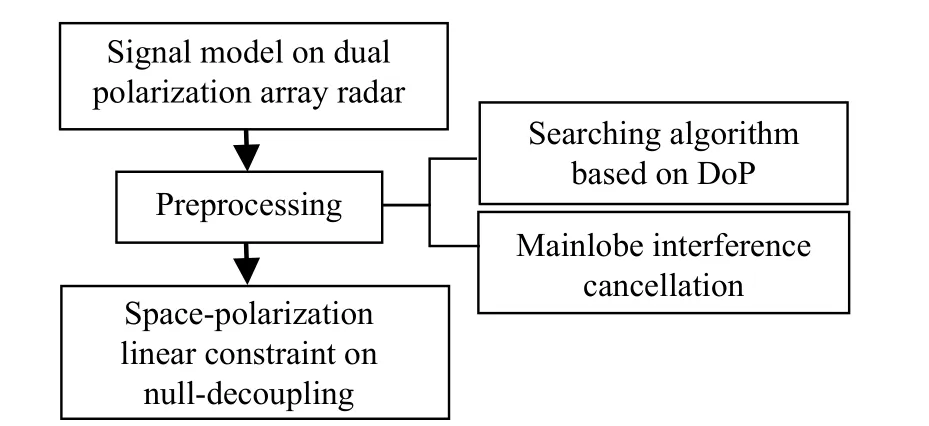
Fig. 1 The proposed signal processing system
The proposed method requires that the polarization information of the interference within 3 dB beam-width is different from that of the target signal. Then, we can effectively distinguish the interference and the target which is adjacent in the space domain. In addition, the proposed null-decoupling in the space-polarization domain is only for the case where there is only one interference within 3 dB beam-width. There is no limit to the number of interferences in the mainlobe outside 3 dB beam-width and the sidelobe.
2. Signal model
Consider a uniform linear array (ULA) composed of N sensors separated by a half wavelength as d = λ / 2. Each sensor has two mutually orthogonal signal receiving channels as H (horizontal) and V (vertical). p is the uncorrelated interference including one mainlobe interference within 3 dB beam-width (hereinafter referred to as the mainlobe interference), one mainlobe interference outside 3 dB beam-width (hereinafter referred to as the nearmainlobe interference) and p-2 sidelobe interferences,where p < N. The characteristic parameters of the signal in the space-polarization domain are θ and (γ, η), the former is the space angle, and the latter is the polarization phase descriptor.
In order to facilitate the analysis, η is fixed as η = 90°,that is, the signals are limited to be located in the same circular orbit of the poincare sphere.
Assume that the space angles and polarization angles of interferences are θi(i=1,2,···, p) and γi(i=1,2,···, p),where (θ1,γ1) represents the mainlobe interference parameter and (θ2,γ2) represents the near-mainlobe interference parameter. The received snapshots that are composed of interferences and noise at k time can be expressed as

where xi(k) (i=1,2,···,N) is the received signal of the ith array sensor, n(k) is the independent and identically distributed Gaussian white noise, li(k) (i=1,2,···, p) is the interferences envelope in the time domain, θiis the direction of the ith interference, and the corresponding joint steering vector of space-polarization is s(θi, γi). It can be expressed as s(θi, γi) = p(θi, γi) ⊗ a(θi), where p(θi, γi) is the polarization vector and a(θi) is the space steering vector as

where (·)Tis the transpose operator. The H and V single channel received signals of the array can be expressed as

3. Angle estimation of interference based on eigenbeam
This part provides the initial searching value for the searching algorithm in Section 4. Taking the H channel processing as an example, the V channel is the same. The covariance matrix of the received signal by the H channel can be expressed as

where (·)Hare the Hermitian transpose operators, Eigenvalues λ1≥λ2≥···≥λN-1≥λNcorrespond to the N eigenvectors e1,e2,···,eN-1,eNrespectively, p larger eigenvalues refer to interferences, and N-p smaller eigenvalues refer to noise.
Taking the eigenvectors corresponding to the p larger eigenvalues as the weights, the eigenbeam of each interference can be obtained. By using the angle directivity of the eigenvectors, we can regard each eigenvector after normalization separately as a class-steering vector [32],then the corresponding interference angles(i=1,2,···,p) can be estimated as

where angle(·) is the phase solving function.
For each interference signal, the final space angle estimationin this part is based on the eigenbeam corresponding to the larger eigenvalue between H and V channels.
4. The proposed method
This part includes a filtering preprocessing and a linear constraint based on null-decoupling. The preprocessing is combined with a searching algorithm for the interference accurate estimation based on the DoP and a mainlobe interference cancellation method.
4.1 Accurate angle estimation of interference based on DoP
In order to estimate the space angle of the interference in the mainlobe accurately, we take the DoP as the index,and propose a searching algorithm.
For the near-mainlobe interference, based on the estimated valuethe searching range isθsis the changing searching angle, and Δθ is the single side searching range. It is verified that when Δθ is set to one sixth of the mainlobe beam-width, the algorithm can achieve good estimation results. For each searching angle, set the following linear constraints:

According to the weight of beamforming calculated in(7), the near-mainlobe and sidelobe interferences can be suppressed. The mainlobe interference of H and V channels ξHξVare extracted as follows:

For each searching angle, we can calculate the DoP of the extracted approximate mainlobe interference in (8).As a kind of polarization rotation invariant, the DoP has a strong robustness in characterizing the polarization characteristics of the signal. In this paper, the DoP is used to characterize the waveform correlation of the extracted interference signal from H and V channels.
We can get the polarized Stokes vector G as
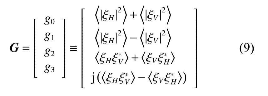
where (·)* is the conjugate calculation operator. The DoP is calculated as

The larger the DoP is, the purer the mainlobe interference is extracted. The searching angle corresponding to the maximum of the DoP is the accurate estimation of the near-mainlobe interference space angle. In order to improve the calculation amount, we combine the particle swarm optimization (PSO) [33] to optimize the traversal process of the searching algorithm.
In the same way, we can get the accurate estimation of the mainlobe interference space angleand the sidelobe interference space angle(i=3,4,···,p).
The accurate estimation of the space angle in this part is important for the proposed method. The searching algorithm based on the DoP guarantees the following estimation accuracy of polarization parameters and the mainlobe interference suppression performance.
4.2 Mainlobe interference cancellation
Combined with the accurate space angle estimation of each interference in Subsection 4.1, the weight ωgto extract the mainlobe interferences can be obtained. The extracted mainlobe interferences of H and V channels are
Taking the mainlobe interference cancellation of the H channel as an example, to calculate the cancellation weight ωi(i=1,2,···, N) of each array sensor channel, the sidelobe cancellation algorithm is used for reference, and the steepest gradient idea is used to minimize the residual signal power of εiin (11). The weight can be obtained by iterative calculation [29].

where xHi(i=1,2,···, N) is the received signal of each sensor channel (that is each row of xH).
With the cancellation weight ωi(i=1,2,···, N), ξHcan be cancelled with xHi(i=1,2,···, N) according to (12). Then we can get the sensors ’ signal zHi(i=1,2,···, N) of the H channel which eliminates the mainlobe interference.

After the same processing of the V channel, we can get the joint space-polarization receiving signal z which eliminates the mainlobe interference.
4.3 Filtering criterion based on null-decoupling
The estimated polarization phase descriptorof the mainlobe interference can be calculated by the mean value of the amplitude ratio and phase difference ofandThe process is as follows:
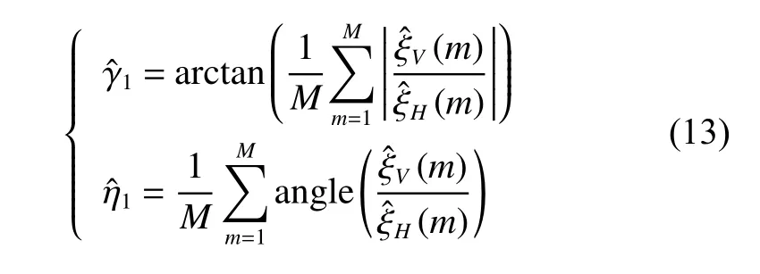
where M is the number of signal sampling.
Since the received signal has eliminated the mainlobe interference, the polarization at the space direction of the mainlobe interference needs to be set as its orthogonal polarization, so that only the null in the polarization domain can be formed for the mainlobe interference suppression. The orthogonal polarization phase descriptoris calculated as follows:

Therefore, at the mainlobe interference, the weight of the array pattern of the proposed method should be able to make H and V receiving channels meet the following equation:

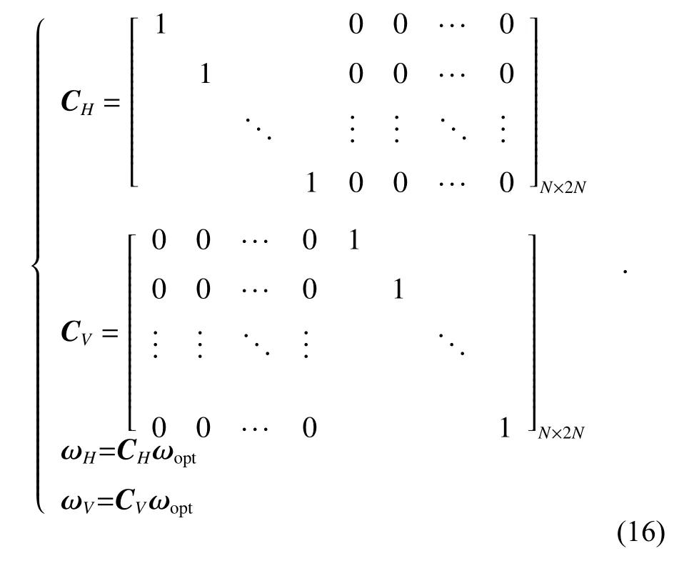
Therefore, (15) can be expressed as

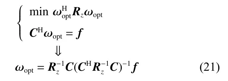
In order to eliminate the invalid solution where ωoptis all zero, the following linear constraint in (18) should be added. We just need to ensure that the signal response of the H channel is not zero, so that the V channel will be limited accordingly.

It is known that the space angle of the look direction is θ0, the polarization angle of the transmitting antenna is γ0,and the joint steering vector of the look direction is s(θ0,γ0). Equation (19) is applied to the distortionless constraint in the direction of the transmitting antenna.

The covariance matrix of the received signal z in the space-polarization domain without the mainlobe interference can be obtained as

On the basis of adaptive filtering with the minimum interference-noise power, the filtering criterion in this paper can be summarized as follows:
5. Simulation results
The simulations are carried out to verify the performance of the proposed method. A uniform linear array with 17 sensors separated by a half wavelength is considered.The look direction is 0°. The polarization phase descriptor of the receiving polarization is (5°,90°). The space angle θ, the polarization phase descriptor (γ,η) and the array channel’s signal-to-noise ratio (SNR) of the target signal and the interference-to-noise ratio (INR) of interferences are shown in Table 1.

Table 1 Signal parameters
Interference 1 is the mainlobe interference, Interference 2 is the near-mainlobe interference, and Interference 3 is the sidelobe interference. The Gaussian white additive noise is considered.
When the three interferences exist at the same time,Fig. 2 shows the eigenbeam corresponding to each interference in the method described in Section 3. Fig. 3 shows the space angle estimations of the interference by the searching algorithm based on the DoP proposed in Section 4. It can be found that the proposed estimation method obtains more accurate space angle estimations of the interference.
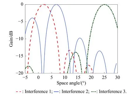
Fig. 2 Eigenbeams of interferences
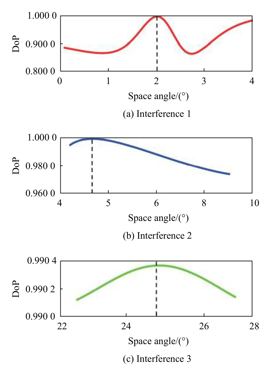
Fig. 3 Searching algorithm on each interference
In order to evaluate the estimation effect of the proposed method of two adjacent interferences in the mainlobe,we make a comparison between the estimation based on the eigenbeam and the estimation based on the DoP. Fig. 4 shows the standard deviation (SD) of the estimation by 200 Monte Carlos versus the space distance between the two interferences in the mainlobe.
We can see that the estimation based on the DoP is less affected by the space distance of the two interferences in the mainlobe. It has a higher estimation accuracy and it is more stable than the estimation based on the eigenbeam.
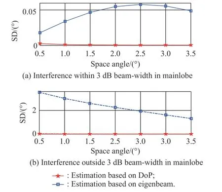
Fig. 4 SD of the estimation versus the space distance between the two interferences in mainlobe
In order to evaluate the estimation effect of the polarization parameterof the mainlobe interference, the statistical analysis results of the estimation by 200 Monte Carlos versus the space distance between the two interferences in the mainlobe are calculated. The statistical analysis results of the estimation errors between the estimated mean value and the true value are shown in Fig. 5.The statistical analysis results of the SD of the estimation are shown in Fig. 6.
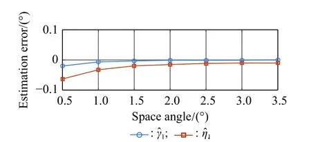
Fig. 5 Estimation error of the polarization parameters estimation versus the space distance between the two interferences in mainlobe
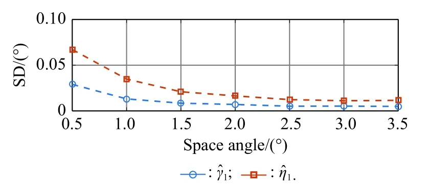
Fig. 6 SD of the polarization parameters estimation versus the space distance between the two interferences in mainlobe
We can see that with the increase of the space distance between the two mainlobe interferences, the SD of the polarization parameters estimation will increase correspondingly, but the estimation errors in Fig. 5 show that the overall estimation effect is very considerable.
Fig. 7 shows the comparison of the adaptive array pattern in the mainlobe between the spatial sample matrix inverse (SMI), the maximal outputting signal to interference plus noise ratio (SINR) filtering method in the spacepolarization domain in [30] and the proposed method.
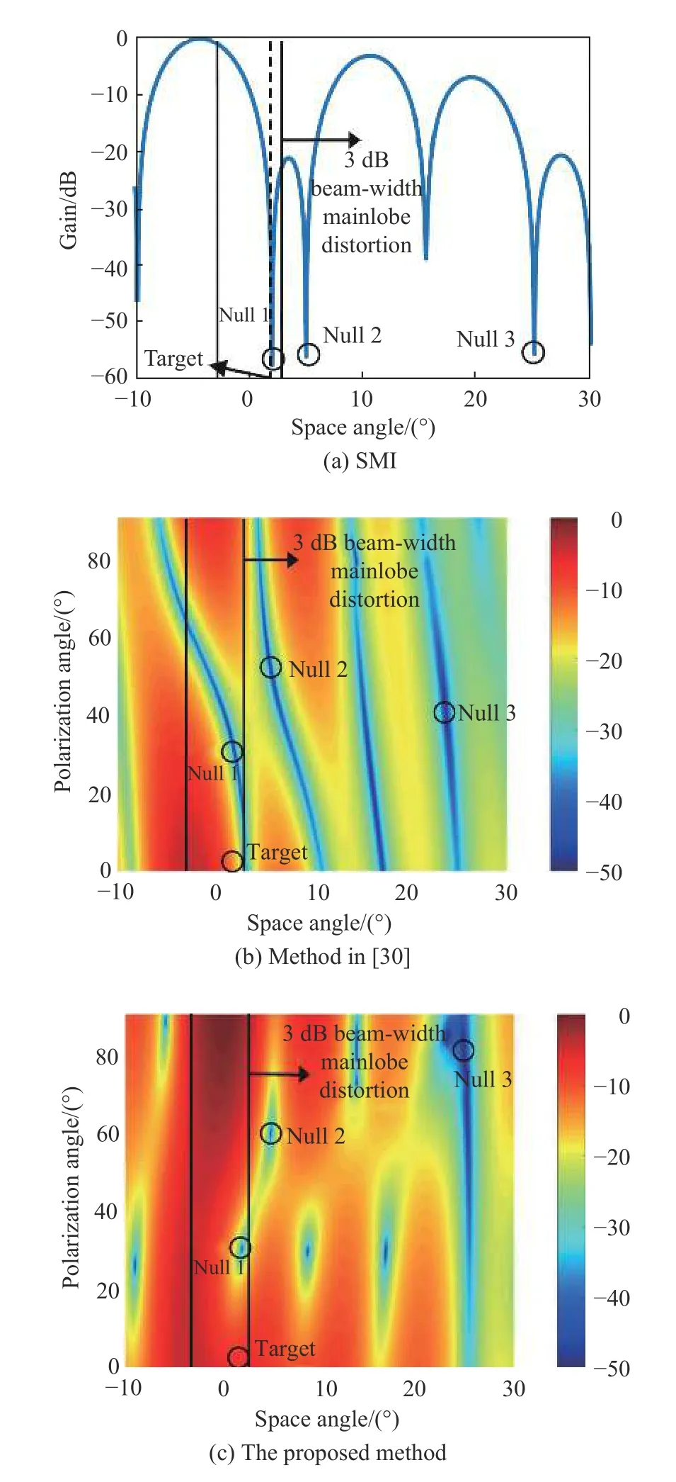
Fig. 7 Adaptive array patterns
It is found that in 3 dB beam-width of the mainlobe,the proposed method can effectively relieve the serious mainlobe distortion while SMI and the method in [30]cannot. The location of nulls, the gain at the interference and the gain at the target direction are calculated in Table 2(the nulls are represented by the space angle θ and polarization angle γ).

Table 2 Comparison between three methods
We can see that for the method in [30], due to the mutual influence between the interferences, the interference with stronger energy affects the nulling position of the interference with weaker energy. The nulling position within the mainlobe of the proposed method is more accurate than that of other methods. The gain at target direction of the proposed method is also higher than that of other methods.
The mixed signals of interferences, noise and target signals before and after the interference suppression with the three methods are shown in Fig. 8. The real lines in Fig. 8 are the mean values of the SNRs of the mixed signals and the output signals after the interference suppression. We can see that the three methods can achieve the same degree of the interference cancellation ratio about 50 dB under the interference conditions in this paper.However, SMI cannot keep the target signal. The method in [30] can suppress the interference effectively, but its target signal has more loss compared with that of the proposed method because of the mainlobe distortion. It is obvious that the proposed method can suppress the interference effectively while obtaining the best output SNR performance.
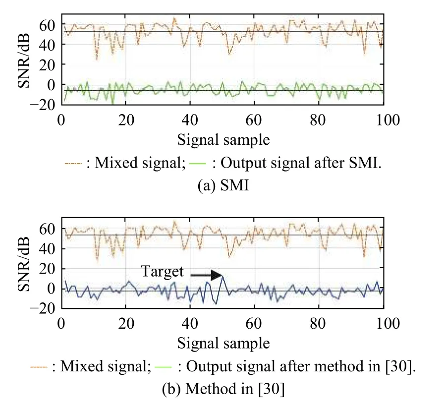
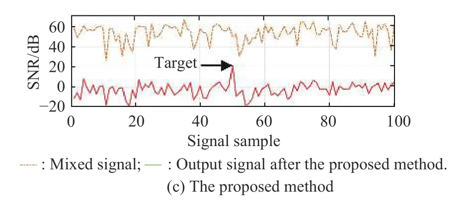
Fig. 8 Output signals before and after three interference suppression methods
In order to evaluate the calculation amount, we compare the proposed method without PSO, the proposed method with PSO and the method in [30]. The central processing unit (CPU) is Intel(R) Core(TM) i7-7700 with 3.60 GHz.The computing time of each method is averaged by 200 Monte Carlos. The results are shown in Table 3.

Table 3 Calculation amount comparison
It can be seen that the calculation amount of the proposed method without PSO is more than 50 times of that of the method in [30]. The calculation amount of the proposed method with PSO is about 20 times of that of the method in [30]. The optimization with PSO for the searching algorithm ’s traversal process can greatly reduce the calculation amount.
Simulation results show that the proposed method performs well in the multiple interference suppression and target signal keeping.
6. Conclusions
In this paper, a multiple interference suppression method based on null-decoupling is derived for dual polarization array radar. By the signal preprocessing, the parameters of the interferences in the space-polarization domain are estimated. Then the proposed method realizes the decoupling of the null in the space-polarization domain, which reduces the mainlobe distortion in both space and polarization domains, and keeps the target signal while suppressing the multiple interferences. Simulation results verify that the proposed method performs well.
 Journal of Systems Engineering and Electronics2021年1期
- Journal of Systems Engineering and Electronics的其它文章
- Unsplit-field higher-order nearly PML for arbitrary media in EM simulation
- A deep learning-based binocular perception system
- STAP method based on atomic norm minimization with array amplitude-phase error calibration
- Higher order implicit CNDG-PML algorithm for left-handed materials
- Fast and accurate covariance matrix reconstruction for adaptive beamforming using Gauss-Legendre quadrature
- Monopulse instantaneous 3D imaging for wideband radar system
