Line-of-sight rates extraction of roll-pitch seeker under anti-infrared decoy state
LI Yue, HE Lei, and XIA Qunli
1. School of Aerospace Engineering, Beijing Institute of Technology, Beijing 100081, China;2. Sichuan Institute of Aerospace Systems Engineering, Chengdu 610100, China
Abstract: In this paper, the method of extracting guidance information such as the line-of-sight (LOS) rates under the anti-infrared decoy state for the roll-pitch seeker is researched. Coordinate systems which are used to describe the angles transform are defined. The LOS angles reconstruction model of the roll-pitch seeker in inertial space is established. A Kalman filter model for extracting LOS rates of the roll-pitch seeker is proposed. In this model, the target performs constant acceleration(CA) model maneuvers. The error model of LOS rates extraction under infrared decoy state is established. Several existing methods of extracting LOS rates under anti-infrared decoy state are listed in this paper. Different from the existing methods, a novel method that uses extrapolated values of target accelerations as filter measurements is proposed to solve the guidance information extraction problem under the anti-infrared decoy state. Numerical simulations are conducted to verify the effectiveness of the proposed method under different target maneuvering models such as the CA model, the CA extended model and the singer model. The simulation results show that the proposed method of extracting guidance information such as LOS rates for the rollpitch seeker under the anti-infrared decoy state is effective.
Keywords: line-of-sight (LOS) rate extraction, roll-pitch seeker,anti-infrared decoy, Kalman filter, target maneuver.
1. Introduction
In the high altitude and high speed air combat environment, the infrared seeker is more and more widely used in air-to-air missile [1-3]. As a kind of the infrared seeker,the infrared semi-strapdown roll-pitch seeker has the advantages of small volume and large field of view [4-6].An important function of the seeker is to obtain guidance information such as relative distance, relative velocity,line-of-sight (LOS) angles, LOS rates and accelerations of the target and the missile. Unlike the platform seeker,the roll-pitch seeker cannot directly measure the LOS rates. Therefore, we usually design suitable LOS rate extraction schemes to obtain the guidance information. The commonly used extraction schemes are direct extraction methods [7], filtering estimation methods [8,9] and tracking differentiator estimation methods [10,11]. The common feature of these methods is that the seeker can always track the real target.
The infrared seeker recognizes the target by sensing infrared energy. Therefore, the infrared seeker is easily disturbed by the infrared decoy that is released by the target[12,13]. The process from releasing the infrared decoy to seeker recognition of the real target is called the anti-infrared decoy state. In this state, the roll-pitch seeker is not tracking the real target, but the energy center of the real target and the infrared decoy. Therefore, the above-mentioned LOS rate extraction methods [7-11] are no longer applicable. Infrared decoy jamming leads to inaccurate guidance information that is obtained by the seeker, which will seriously affect the guidance accuracy of the missile[14,15].
In order to counter infrared decoy jamming, many methods have been proposed. Li et al. [16] established an infrared anti-jamming operational effectiveness evaluation model. Dai et al. [17] proposed a method that the missile can quickly identify the infrared decoy by infrared characteristics such as temperature and infrared energy. These methods [16,17] only focus on identifying the target and do not explain how to obtain guidance information such as LOS rates. Du et al. [18] proposed a method of LOS rates extraction for the platform seeker.Liu [7] established a Kalman filter model of LOS rates extraction for the roll-pitch seeker. Li [15] proposed a method, which can improve the accuracy of the LOS rates extraction for the platform seeker under the anti-infrared decoy state. Some other methods [19-21] consider the effect of the target maneuver on the guidance and control system under the anti-infrared decoy state. All these methods [7,15,18-21] do not solve the problem of extracting the guidance information, such as LOS rates for the roll-pitch seeker under the anti-infrared decoy state completely. In addition, different maneuvering models such as the constant acceleration (CA) model, the CA extended model and the singer model [22-25] should be analyzed, but there are no relative researches.
This paper takes the roll-pitch seeker as the researched object. Aiming at the problem of extracting guidance information such as LOS rates under the anti-infrared decoy state, an optimized method based on the extrapolated estimation of target accelerations is proposed. The rest of this paper is as follows. In Section 2, the useful coordinate systems are defined and the reconstruction model of LOS angles for the roll-pitch seeker is established. In Section 3, the filter model of extracting guidance information is established. Several existing methods and their disadvantages are introduced. The optimized method based on the extrapolated estimation of target accelerations under the anti-infrared decoy state is proposed. In Section 4,numerical simulations are conducted to verify the effectiveness of the proposed method under the CA maneuvering model. In Section 5, numerical simulations are conducted to verify the effectiveness of the proposed method under the CA extended and singer maneuvering model. In Section 6, relevant conclusions are summarized.
2. Principle of LOS angles reconstruction of roll-pitch seeker
2.1 Definition of coordinate systems
The roll-pitch seeker consists of an inner and an outer frames. The outer frame is the roll frame and the inner frame is the pitch frame. This structure allows the seeker’s field of view to cover the entire front hemisphere. Therefore, the missile with the roll-pitch seeker has the advantage of launching with a large off-axis angle. In order to describe the frame motion of the roll-pitch seeker more clearly, various coordinate systems are defined as follows.
(i) Inertial coordinate systemoxyz
The inertial coordinate system is fixed to the earth’s surface. The origin is the projection of the center of mass onto the ground when the missile is launched. The o x axis is the horizontal line on the ground, pointing to the target.The o y axis is perpendicular to the o x axis and points upward in the plumb plane. The oz axis and the other two axes satisfy the right hand coordinate system criterion.
(ii) Body coordinate systemoxbybzb
The body coordinate system is fixed to the missile body. The origin is the center of the mass of the missile.The oxbaxis is the longitudinal axis of the missile body and points to the head of the missile. The oybaxis is perpendicular to the ox axis and points upwards in the longitudinal plane of symmetry of the missile body. The o zbaxis and the other two axes satisfy the right hand coordinate system criterion. The included angles of the body coordinate system and the inertial coordinate system are pitch angle ϑ, yaw angle ψ and roll angle γ.
(iii) Outer frame coordinate systemoxwywzw
The outer frame coordinate system is fixed to the seeker outer frame. The origin is the center of the seeker detector. The oxwaxis overlaps the longitudinal axis of the missile body and points to the head of the missile.The oywaxis is perpendicular to the oxwaxis and points upwards in the outer frame plane. The ozwaxis and the other two axes satisfy the right hand coordinate system criterion. The included angle of the outer frame coordinate system and the body coordinate system is roll frame angle ϕR.
(iv) Inner frame coordinate systemoxnynzn
The inner frame coordinate system is fixed to the seeker inner frame. The origin is the center of the seeker detector. The o xnaxis overlaps the seeker optical axis and points to the target. The oznaxis overlaps the ozwaxis.The o ywaxis and the other two axes satisfy the right hand coordinate system criterion. The included angle of the outer frame coordinate system and the inner frame coordinate system is pitch frame angle ϕP.
(v) LOS coordinate systemoxsyszs
The origin of the LOS coordinate system is the center of the mass of the missile. The o xsaxis overlaps the LOS,pointing to the target. The ozsaxis is in the horizontal plane of the inertial coordinate system. The ozsaxis is perpendicular to the oxsaxis and points to the right. The oysaxis and the other two axes satisfy the right hand coordinate system criterion. The included angles of the LOS coordinate system and the inner frame coordinate system are pitch error angle εpand yaw error angle εy. The included angles of the LOS coordinate system and the inertial coordinate system are pitch LOS angle qpand yaw LOS angle qy.
Fig. 1 shows the transform relationship among abovementioned coordinate systems.
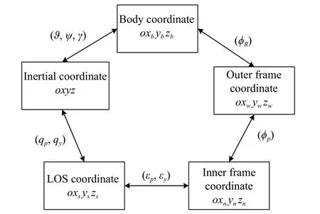
Fig. 1 Transform relationship of coordinate systems
2.2 Reconstruction of LOS angles
u=[1,0,0]Tis supposed as a unit vector along the LOS.The coordinates of the vector in the inner frame coordinate system can be obtained by rotating the angles εpand εybackwards from the LOS coordinate system. In the same way, the coordinates of the vector in the body coordinate system can be obtained by rotating the angles ϕpand ϕRbackwards from the inner frame coordinate system. Therefore, the coordinates of the vector in the inertial coordinate system can be obtained by rotating the angles ϑ, ψ and γ backwards from the body coordinate system.
On the contrary, the coordinates of the vector in the inertial coordinate system can be also obtained by rotating the angles qpand qyforwards from the LOS coordinate system. The coordinates obtained by these two methods are the same.
The coordinate transformation matrix from the LOS coordinate system to the inner frame coordinate system is represented asThe coordinate transformation matrix from the inner frame coordinate system to the outer frame coordinate system is represented asThe coordinate transformation matrix from the outer frame coordinate system to the inner frame body coordinate system is represented asThe coordinate transformation matrix from the body coordinate system to the inertial coordinate system is represented asThe coordinate transformation matrix from the LOS coordinate system to the inertial coordinate system is represented asFrom the above-mentioned analysis, we can get

where
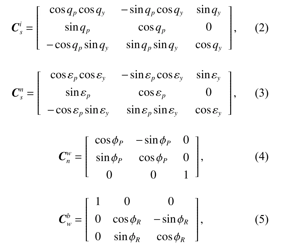

Calculate the left side of (1) and the calculated result can be represented as

From (3) to (6), we can draw a conclusion that

Putting (2) and (7) into (1), we can get

From (8) and (9), we can draw the conclusion that LOS angles of the roll-pitch seeker can be calculated by means of coordinate system reconstruction. Attitude angles, seeker frame angles and detector error angles are required to calculate LOS angles. These required angles can be obtained directly by angle sensors on the missile body and the seeker. The LOS rate can be estimated by taking LOS angles as measurements and establishing the appropriate Kalman filter model.
3. LOS rates extraction under anti-infrared decoy state
3.1 Filter model of LOS rate extraction
The motion between the missile and the target is nonlinear so that extended Kalman filtering (EKF) can be used,which is often used to deal with nonlinear problems. The EKF model for LOS rates extraction is established as follows [7].
In the polar coordinate system, state variables in the filter equation are

where qpand qyare LOS angles,andare LOS rates,R is the relative distance between the missile and the target,is the relative velocity between the missile and the target.
For accurate estimation, the system state equation should also include the accelerations of the missile itself and the accelerations of the target maneuver [7,15]. The accelerations of the missile itself can be measured by the missile body accelerometer so that it is known, while the target accelerations are unknown. Target accelerations can be expanded into state variables, and the system state variables can be expanded into

where atx, atyand atzare target’s maneuvering accelerations.
The maneuvering model of the target has many forms.Many relevant studies are based on given target maneuver models, and the target maneuvering dynamics are also considered. Combined with the information measured by the seeker, this paper firstly assumes that the target performs constant maneuver. The cases that the target performs changeable acceleration maneuver will be analyzed in Section 5.
Maneuvering accelerations in the inertial space are respectively atx, atyand atz. ωx, ωyand ωzare the white Gaussian noises. It is assumed that these noises are unrelated. Accelerations of the missile are represented as amx,amyand amz. According to the CA maneuvering model, the relationship between noise and target acceleration is

The acceleration of the target in the inertial coordinate system is at. The acceleration of the target in the LOS coordinate is atl. According to the derivative rule of vectors,we can obtain

Project the target’s acceleration under the inertial system onto the LOS system, and we can obtain
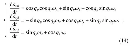
Substituting (14) into (13), we can obtain
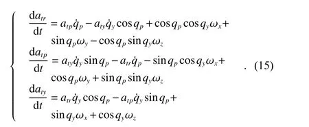
Therefore, the state equations of the system are
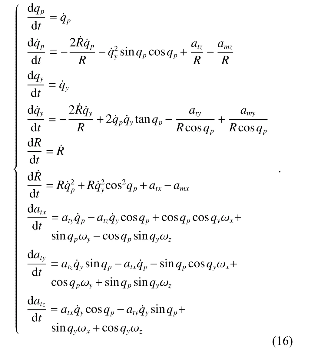
LOS angles are chosen as measurements, which can be calculated by attitude angles, seeker frame angles and detector error angles. Noises of the measurement equation are represented as v1and v2. Measurement equations of the system are

Then the measurement matrix of the system is

3.2 Anti-infrared decoy state and existing methods
The infrared seeker tracks the target by recognizing the infrared energy. After the target releases the infrared decoys, multiple infrared energy sources will appear in the seeker’s field of view. The seeker will track the energy center of these sources until the seeker recognizes the real target. Fig. 2 shows the angular relationship of the energy center, the single decoy and the real target. The real LOS angle is q1. The seeker’s light axis points to the energy center, and q2becomes the recorded LOS angle.
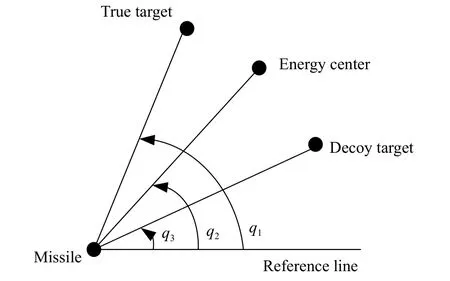
Fig. 2 Seeker tracking the energy center
From Fig. 2, we know that if the seeker tracks the wrong infrared target, detector error angles obtained by the seeker detector will be inaccurate. Seeker frame angles calculated by the seeker servo system will also be inaccurate. According to Section 2, the LOS angle reconstructed by the above-mentioned angles will be also inaccurate. As measurements, these inaccurate LOS angles will cause errors in the guidance information extraction by the filter model. Finally, missile guidance and control accuracy will be affected.
The infrared seeker takes about 0.3 s to recognize the real target from the numerous decoys [26,27]. The state in which the seeker recognizes the real target is called the anti-infrared decoy state. During this anti-infrared decoy state, appropriate measurements need to be selected to ensure that the LOS rate and target maneuver information estimated by the filter model are accurate.
Method 1Select extrapolated values of LOS angles as measurements
In [15], a method that used extrapolated values of LOS angles as measurements under the anti-infrared decoy state was proposed. LOS angles information from the seeker is no longer accurate during the anti-infrared decoy state. Therefore, we can select the LOS angles information at the moment that the target releases the decoy as the replacement. Assume that the target releases the decoy at qp−release, and the LOS angles information obtained from the seeker at the releasing moment are qp−releaseand qy−release. These LOS angles can be called as extrapolated LOS angles. Measurement equations of the system during the anti-infrared decoy state change into

During the anti-infrared decoy state, the LOS rate extraction uses extrapolated LOS angles as the measurement.When the seeker recognizes the real target, the seeker light axis tracks the real target again. LOS angles obtained from the seeker can be used as measurements for the filter model again. The anti-infrared decoy state becomes over this time.
The disadvantage of this method is obvious. Extrapolated LOS angles are not equal to the real LOS angles,and the real LOS angles will change during the anti-infrared decoy state. Using the fixed extrapolated LOS angles as measurements will cause errors when estimating the guidance information by the filter.
Method 2Extract guidance information without measurements
In [7], a method that used Kalman filter without measurements under the anti-infrared decoy state was proposed. Inaccurate LOS angles information will not enter the filter estimator without using the measurement equation.When the seeker recognizes the real target, the seeker light axis tracks the real target again. LOS angles obtained from the seeker can be used as measurements for the filter model again.
The disadvantage of this method is a short period’s time of missing information. Miss the inaccuracy LOS angles information may reduce the error of the LOS rates estimation, but other guidance information such as relative distance, relative velocity and target accelerations may be estimated inaccurately.
3.3 New method: selecting extrapolated estimation of target’s accelerations as measurements
The missile needs guidance information to track its target.The LOS rate is one of the most necessary guidance information. The LOS rate of the roll-pitch seeker needs to be extracted from the known information of the missile and the target by the estimation. Therefore, the key to extract LOS rates accurately is to select the suitable known information.
Fig. 3 shows the guidance and control system of the rollpitch seeker in the normal state. The normal state means no infrared decoy jamming state. From Fig. 3, we know that the roll-pitch seeker obtains and processes the motion information of the missile and the target through the detector, the command unit and so on. The accuracy of the motion information transmitted by the seeker to the filter determines whether the filter can estimate the guidance information such as LOS rate and target maneuver well.
From Section 2, we know that LOS angles can be reconstructed by attitude angles, seeker frame angles and detector error angles. These required angles can be all obtained accurately in the normal state. Therefore, LOS angles are accurate and they can be selected as measurements. By the filter estimation, the guidance information such as LOS rates can be extracted. The whole process is shown in Fig. 3.
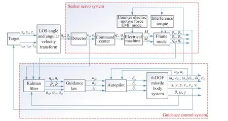
Fig. 3 Guidance control loop of seeker in normal state
When the target releases the infrared decoy, the rollpitch seeker cannot track the real target anymore. Detector error angles become inaccurate and LOS angles become inaccurate, too. To continue the filter estimation process, the replaced known quantities need to be selected as measurements.
Before the anti-infrared decoy state, all of these nine state variables can be estimated by the filter model, which means that the accelerations of the target ( atyand atz) have been estimated. Under the case that the target performs the CA maneuvering model, we can make two assumptions.
Assumption 1The target performs a constant maneuver.
Assumption 2The target will only release the decoy to avoid tracking by the missile, and the maneuver accelerations will not change during the anti-infrared decoy state.
The target’s accelerations at the moment that the target releases the decoy can be represented as aty−releaseand atz−release. The true values of target’s accelerations during the anti-infrared decoy state are represented as aty−antiand atz−anti. From those two assumptions, we know that

From (20), we know that aty−releaseand atz−releasecan be selected as measurements under the anti-infrared decoy state. These accelerations at the releasing moment can be estimated by the filter.
Fig. 4 shows this new method of measurements choosing. Before the anti-infrared decoy state, the guidance and control system uses correct LOS angles as measurements.During the anti-infrared decoy state, the estimated accelerations of the target can be chosen as measurements for the Kalman filter model. Measurement equations of the system change into

where atyand atzare estimated values of target’s y axis and z axis accelerations.
Then the measurement matrix of the system changes into

There are errors between the estimated values and true values, which means

where atyand atzcan be called extrapolated accelerations,∆atyand ∆atzare estimation errors of the filter. These estimation errors may cause inaccurate extraction of the guidance information, which need to be researched in the following simulation.
After the anti-infrared decoy state, the seeker recognizes the real target. The seeker light axis tracks the real target again. LOS angles can be used as measurements for the filter model again. The anti-infrared decoy state becomes over this time. Measurement equations of the system change into

The measurement matrix of the system changes into

This method can be called as the accelerations extrapolated estimation method. The effectiveness of this new method should be verified by the following numerical simulations.
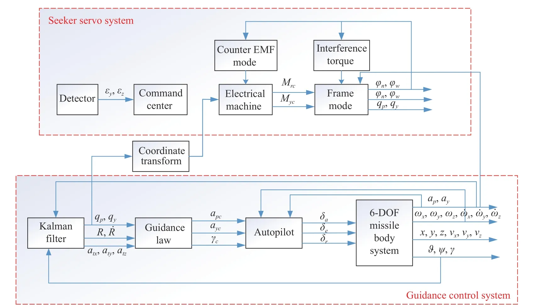
Fig. 4 Guidance control loop of seeker under anti-infrared decoy state
4. Simulation and validation under CA model
At first, we assume that there is no error between the estimated target acceleration and the real target acceleration.∆atyand ∆ atzare zero. Set appropriate motion parameters of the missile and the target. Simulate the anti-jamming methods mentioned in Subsection 3.2 and Subsection 3.3 respectively. After this simulation, the condition that there are errors between the estimated target acceleration and the real target acceleration is considered in Subsection 4.2. In the process of simulation and comparison among three filtering methods, the following two comparison items are commonly used to evaluate the advantages and disadvantages of three methods:
∆f, the absolute value of the estimated value fluctuation’s crest during the identification process, which is the period of 5.0-5.3 s in our simulation;
∆E, the absolute value of the error between the estimated value and the true value. In the calculation process,a set of absolute error values ∆E1,∆E2,···,∆En(n ≥10)after 8 s can be taken and we can obtain their mean valuesby statistical methods.
Since the estimated values of Kalman filtering will be applied to the guidance system of air-to-air missiles, the large fluctuation in the data update process will cause instability in the guidance system so that we want the data fluctuation during 5.0-5.3 s to be as small as possible. In addition, the error between the estimated value and the real value cannot be too large, which will also cause the decrease of guidance precision of air-to-air missiles.Therefore, the smaller ∆f is, the smoother the identification process is, which means the method is more helpful to the stabilization of the guidance system. The smalleris, the better the filtering effect is, which means the filtering method is more helpful to the stabilization of the guidance system.
4.1 Comparison among several methods
Initial simulation conditions are as follows. Set the relative distance between the missile and the target at the initial moment R as 10 km. Set the relative velocitybetween the missile and the target as 1 000 m/s. The initial values of the LOS angles are qp=1°and qy=5°. The initial value of the LOS rate is zero. The accelerations of the target in the LOS coordinate system are atx=10 m/s2,aty=−30 m/s2and atx=−60 m/s2. The initial state of the Kalman filter is shown in Table 1. The initial estimation errors of the state variables are shown in Table 2.
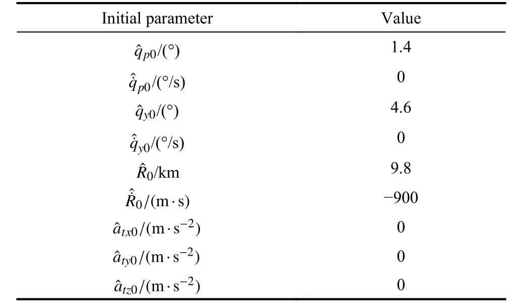
Table 1 Initial value of Kalman filter estimation
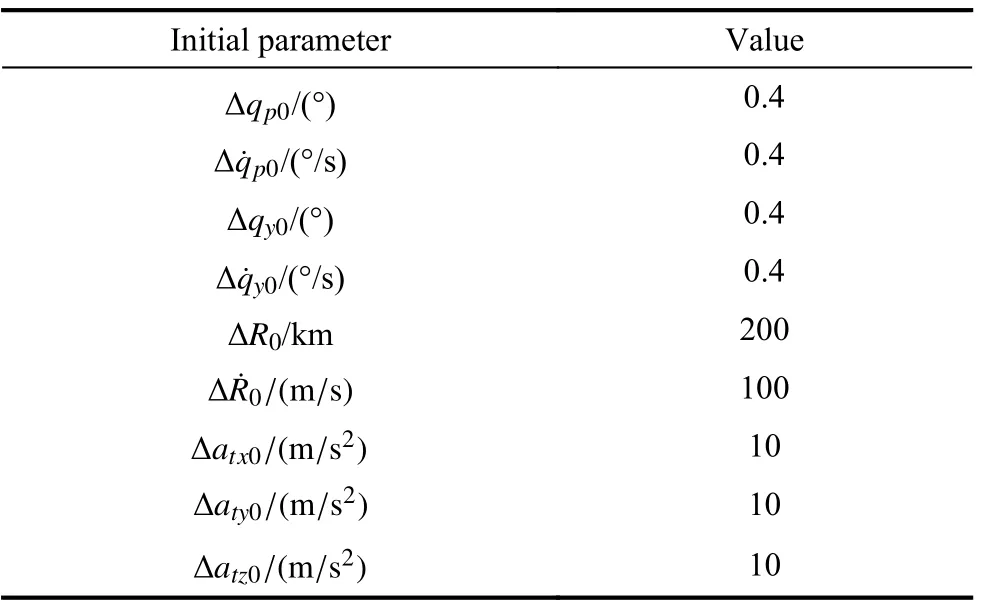
Table 2 Initial estimation error of state variables
Take the initial covariance matrix as

The following simulations show the comparison of these existing methods mentioned in Subsection 3.2 with the new method proposed in Subsection 3.3. Set the beginning time of the anti-infrared decoy state as 5 s. The relative velocity between the decoy and the real target is 50 m/s in the y and z axes. After 0.3 s, the decoy can be recognized by the seeker. Simulation of various cases and the measurements selection is shown in Table 3. Figs. 5-14 show the simulation results.
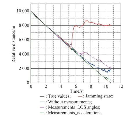
Fig. 5 Simulation of R
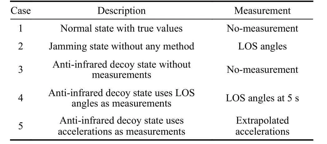
Table 3 Different cases with measurements
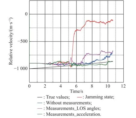
Fig. 6 Simulation of ˙R
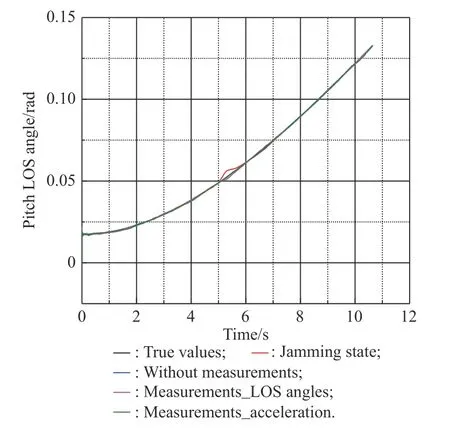
Fig. 7 Simulation of qp
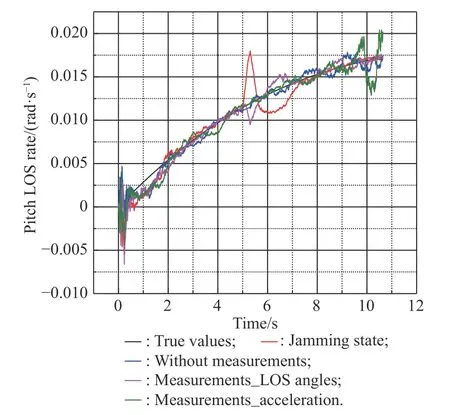
Fig. 8 Simulation of
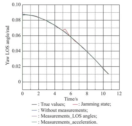
Fig. 9 Simulation of qy
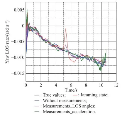
Fig. 10 Simulation of
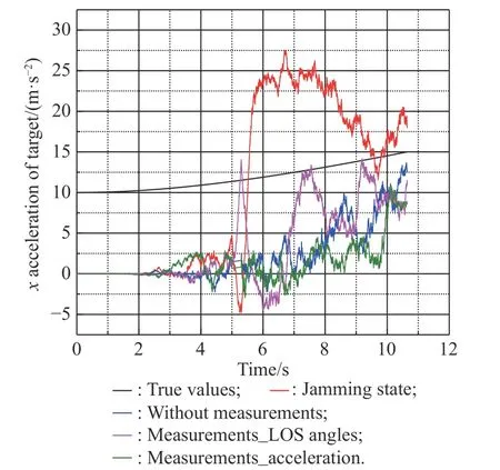
Fig. 11 Simulation of atx
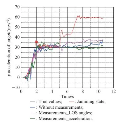
Fig. 12 Simulation of aty
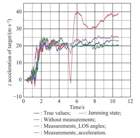
Fig. 13 Simulation of atz
Figs. 5-13 show the simulation results of state estimation ofFive cases are all shown in each figure. Fig. 14 shows the motion of the missile and the target.
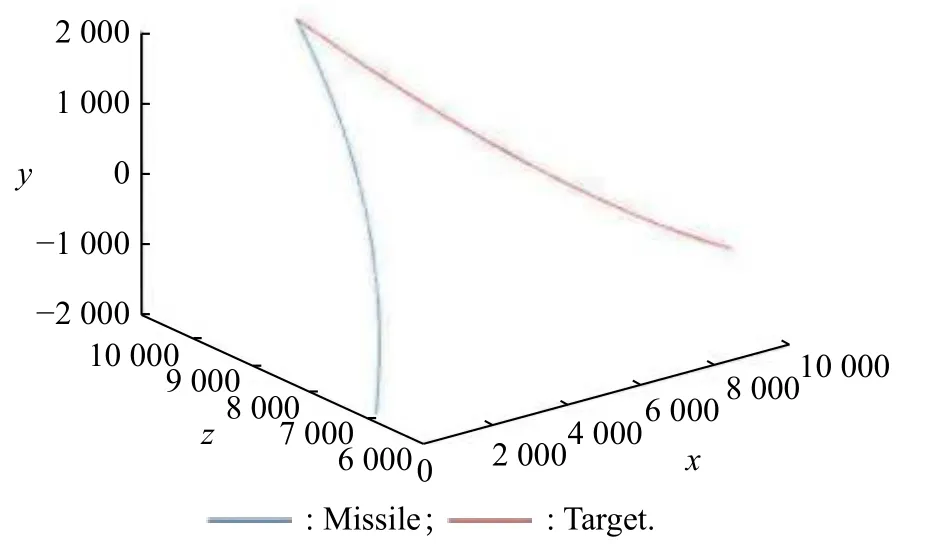
Fig. 14 Motion of the missile and the target
From Fig. 5 and Fig. 6, we know that the jamming state has a deep influence on the estimation of relative distance and relative velocity. There are big errors between the results of the jamming state and the true values. Three filtering methods reduce the error in varying degrees. Because of using inaccurate information during the anti-infrared decoy state, the effect of the method with the LOS angle at 5 s is the worst. The effect of the method with accelerations as measurements is better than the method without measurements for the reason of using accurate information.
From Fig. 7 and Fig. 8, we know that the jamming state will cause a large deviation from the true LOS angles and LOS rate estimation values during the period from 5 s to 5.3 s. The method that uses LOS angles at 5 s as measurements reduces the error, but there is still a small deviation from the true values. The method with acceleration estimates the LOS angles and the LOS rate more accurately than the method without measurements.Fig. 9 and Fig. 10 show the estimated LOS rates. From the figures, we can find that the estimated effect of the new method seems to be closed to that of Method 1 and Method 2. The process of the anti-infrared decoy and target recognition for the roll-pitch seeker is only 0.3 s. Although there will be error on the measurement when using Method 1 or Method 2, since the recognition process is short, the roll-pitch seeker can obtain the correct LOS angle information after 0.3 s again. In addition, the LOS rates filtering estimation is relatively direct, which will be less affected by the measurement error [28,29]. Therefore, the LOS rates estimated effect of Method 1 and Method 2 are closed to that of the new method. However,after 10 s, the estimated value of the new method oscillates obviously. Oscillation is caused by the changeable structure parameters of the filtering algorithm. For comparison, we set the filter structure parameters of the three methods to be the same. However, in the practical application of the algorithm, the filter structure parameters will be optimized and adjusted to reduce the interference effect of the filtering noise [30]. Therefore, the oscillations at the end of Fig. 8 and Fig. 10 will not affect the normal use of the filtering method.
From Figs. 11-13, we know that the jamming state will causes big errors when the filter estimates the accelerations of the target. From Fig. 11, we know that the estimated effect of atxunder all the three methods are not well.That is because the estimated effect of atxis related to the relative distance and relative velocity. Unlike the commonly used pitch-yaw seeker, the roll-pitch seeker cannot directly obtain relative distance and relative velocity which are also obtained by the filtering estimation. Therefore, the estimation effect of atxis generally not well under all the three methods. However, since atxis not applied to the guidance law, the estimation effect of atxis not well,which will not affect the normal operation of the guidance system of air-to-air missiles [31,32].
For the estimation of y and z accelerations, the three methods have good effects on reducing errors. The effect of the method with accelerations as measurements is better than the other two methods.
Comparing the data in Table 4, we can find that except Fig. 11, ∆f of Method 2 is generally larger than that of Method 1 and the new method. This indicates that except the estimation of atx, Method 2 will have a larger data fluctuation in the process of target recognition than Method 1 and new method 3. From the previous analysis, we know that the three methods are not effective for atxestimation.

Table 4 Summary of specific data in Figs. 5−13
4.2 Situations with estimation errors
When the anti-infrared decoy state starts, the Kalman filter model uses the target accelerations estimated before the anti-infrared decoy state as the measurements. There may be errors between the estimated accelerations and the true accelerations of the target. The following simulation considers the influence of the estimated error on the guidance information extraction of the accelerations extrapolated estimation method.
Fig. 15 and Fig. 16 show errors between the target’s real accelerations and the estimated accelerations under the normal state. The red dotted lines show the theoretical boundary of the error, which is calculated by the error covariance matrix of the Kalman filter model.
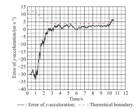
Fig. 15 Estimation error of aty and the theoretical boundary
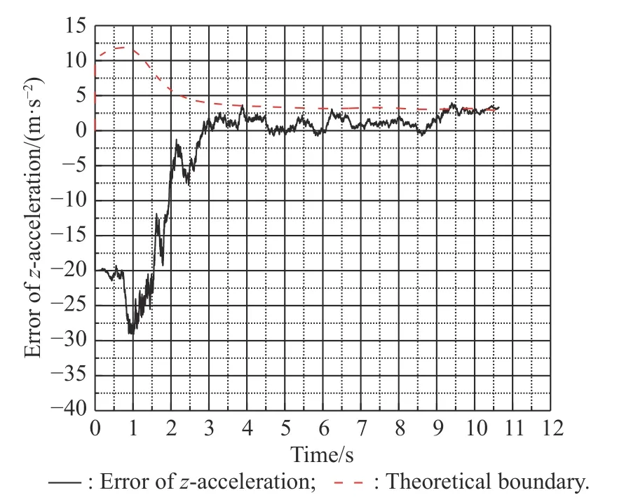
Fig. 16 Estimation error of atz and the theoretical boundary
From Fig. 15 and Fig. 16, we know that errors between estimated accelerations and the real accelerations are limited in a theoretical range. Calculated by the error covariance matrix, the error range for atyis from -4 m/s2to 4 m/s2, and the error range for atzis from -3 m/s2to 3 m/s2. Combined with the simulation results in Fig. 15 and Fig. 16. The error range can be modified as 0-4m/s2for aty, and 0-3 m/s2for atz. Next, we will select several error cases within the error range to simulate the influence of these errors on the accuracy of the extrapolation estimation strategy. Table 5 shows the error cases that will be simulated. Figs. 17-22 show the simulation results.
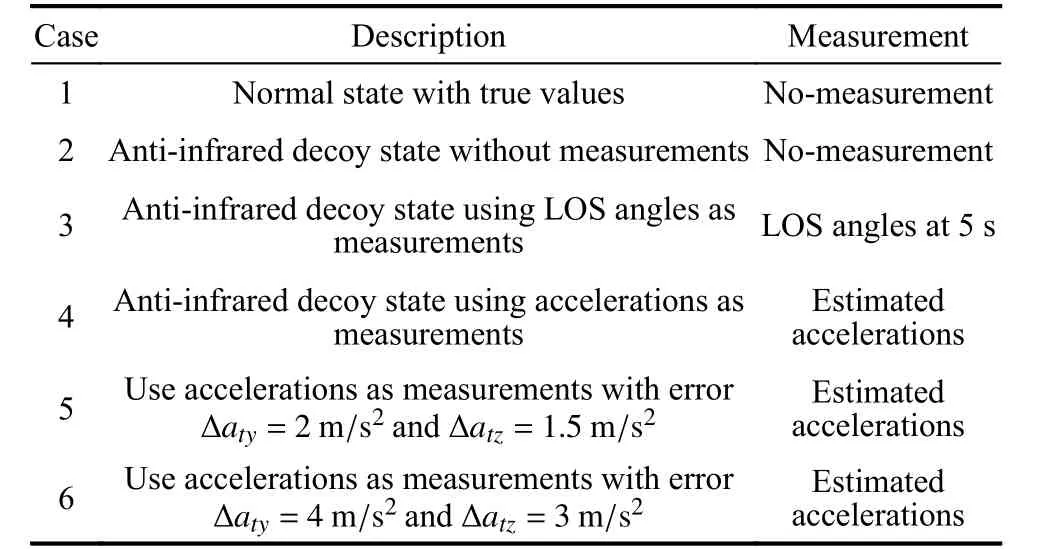
Table 5 Different error cases and compared methods
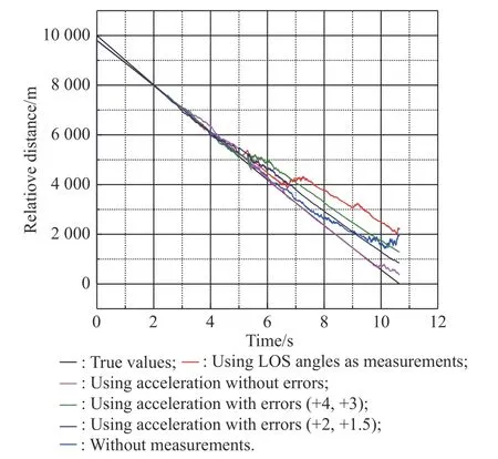
Fig. 17 Simulation of R with estimation errors
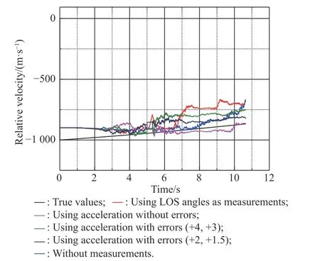
Fig. 18 Simulation of R˙ with estimation errors
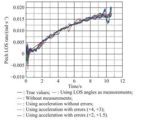
Fig. 19 Simulation of with estimation errors
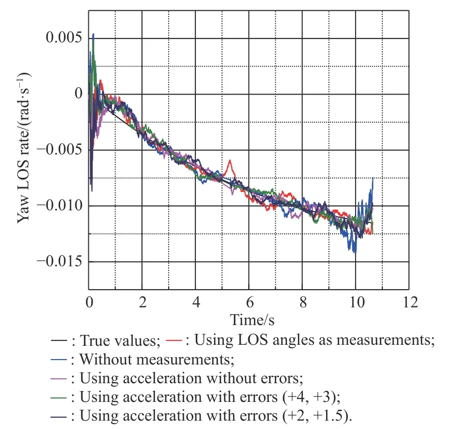
Fig. 20 Simulation of with estimation errors
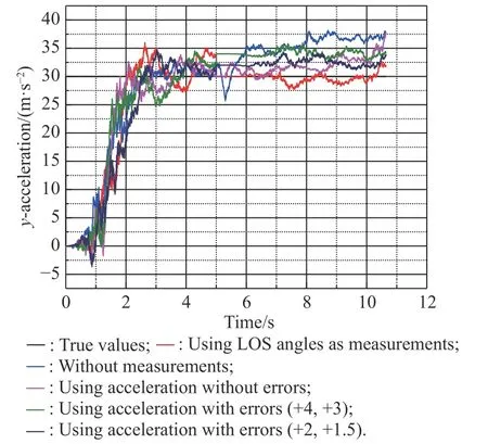
Fig. 21 Simulation of aty with estimation errors
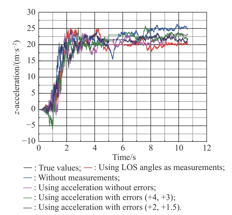
Fig. 22 Simulation of atz with estimation errors
Table 6 shows the specific data of Figs. 17-22, in which Method 1 uses LOS angles as measurements,Method 2 is the method without measurements, Method 3 uses the acceleration as measurements, Method 4 uses the acceleration as measurements with errors of ∆ aty=4 m/s2,∆atz=3 m/s2, and Method 5 uses the acceleration as measurements with errors of ∆ aty=2 m/s2, ∆ atz=1.5 m/s2.

Table 6 Summary of specific data in Figs. 17−22
From Fig. 17, Fig. 18 and Table 6, when we use the target’s accelerations as measurements, we know that the estimation error of target accelerations will cause inaccurate extraction of relative distance and relative velocity.The greater the estimation errors of accelerations are, the greater the influence on relative velocity and relative distance estimation will be. However, within the estimation error range of the filter, even if the estimation of accelerations are not accurate, the relative distance and relative velocity extraction accuracy of the accelerations extrapolation estimation method are better than that of the method using LOS angles as measurements or the method using no measurement.
From Fig. 19, Fig. 20 and Table 6, we know that several methods can all extract LOS rates well. The measurements error of the accelerations estimation will cause the error of extracting LOS rates, but the effect is not serious within the estimation error range of the filter.
From Fig. 21, Fig. 22 and Table 6, we know that for the method of using accelerations as measurements, the estimation error will affect the accuracy of the target’s accelerations estimation. The effect is obvious when the error becomes bigger. However, within the estimation error range of the filter, even if the estimation of accelerations are not accurate, the accelerations extraction accuracy of the accelerations extrapolation estimation method is better than that of the method using LOS angles as measurements or the method using no measurement.
5. Anti-infrared decoy strategy for target with variable acceleration
When the air-to-air missile is tracking the target, the target can not only release the infrared decoy, but also escape by large maneuver in a short time. In addition to the usual CA maneuver model, the target may be maneuvering with variable acceleration. There are two ways of changing the acceleration in a short period of time, continuous change and dispersed change. The common continuous change model of target acceleration is the CA extended model, and the common dispersed change model of the target acceleration is the singer model. In the following, we will verify the effect of our new LOS rates extraction method through the simulation in the cases that the target releases the infrared decoy with the CA extended maneuver or singer maneuver.
5.1 Target maneuver with CA extended model
The target maneuvering model discussed in Section 3 and Section 4 is the CA model, and the target acceleration is assumed to be constant. The derivative of the target acceleration is only the noise quantity. When the target continuously increases maneuver overload to avoid air-to-air missile tracking, the target acceleration may perform the CA extended model, and the target maneuver model at this time will change continuously and uniformly.
Assume that maneuvering accelerations in the inertial space are atx, atyand atzrespectively. ωx, ωyand ωzare the noise. k is the changing coefficient of acceleration,which is a constant. According to the CA extended maneuvering model, the relationship between noise and target acceleration is
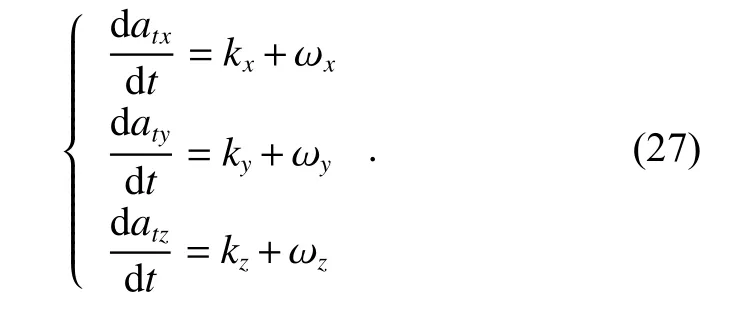
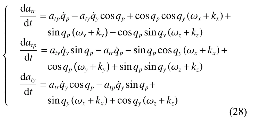
According to the vector derivation equation and coordinate transformation, which we mentioned in Section 3,we can obtain the new state equation of target accelerations.
Other state equations are the same as that in (16).
We can set the suitable initial simulation conditions as follows, which are the same as the initial simulation conditions in Subsection 4.1. Set the relative distance between the missile and the target at the initial moment R as 10 km. Set the relative velocitybetween the missile and the target as 1 000 m/s. The initial values of LOS angles are qp=1°and qy=5°. The initial value of the LOS rate is zero. Set k as 0.5 in the simulation and the initial accelerations of the target in the LOS coordinate system are atx=10 m/s2, aty=−30 m/s2and atx=−60 m/s2.Table 7 shows several types of simulation conditions with different filtering methods. Figs. 23-28 show the simulation results under the CA extended model with different methods. Table 8 shows the specific data of these figures.
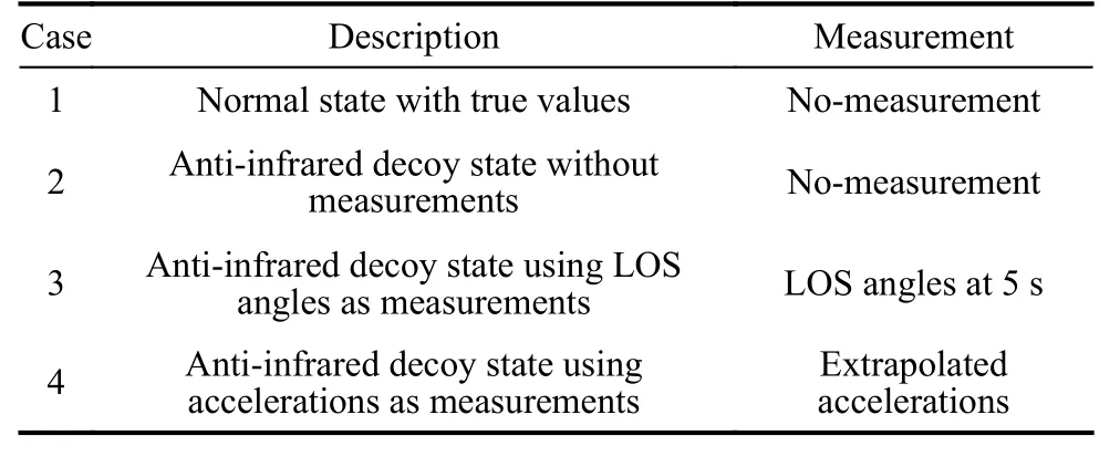
Table 7 Different cases with measurements with the CA extended model
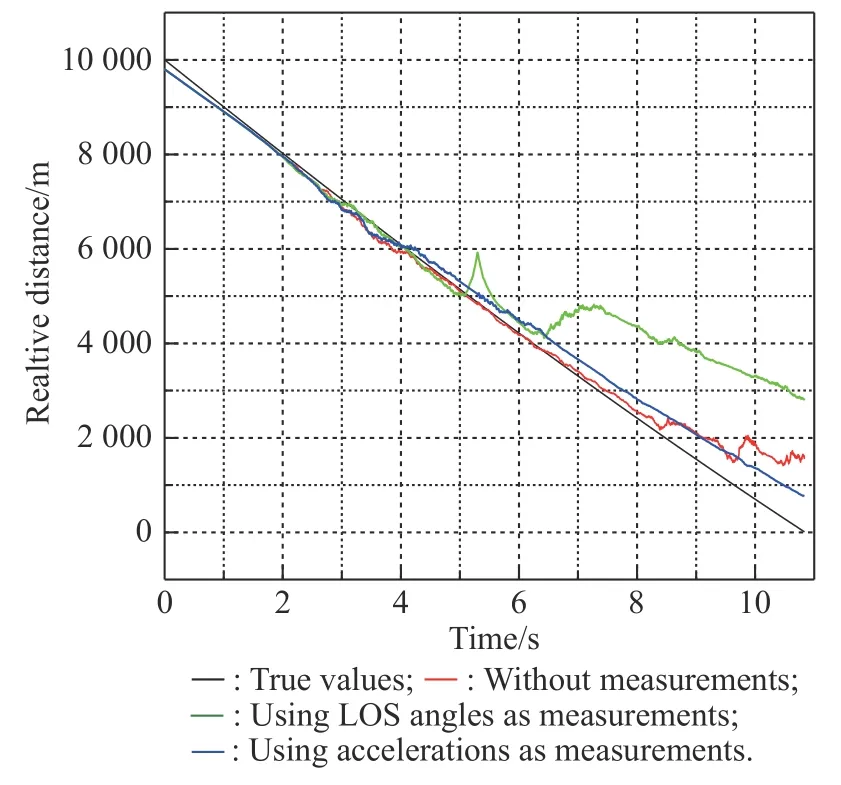
Fig. 23 Simulation of R with the CA extended model
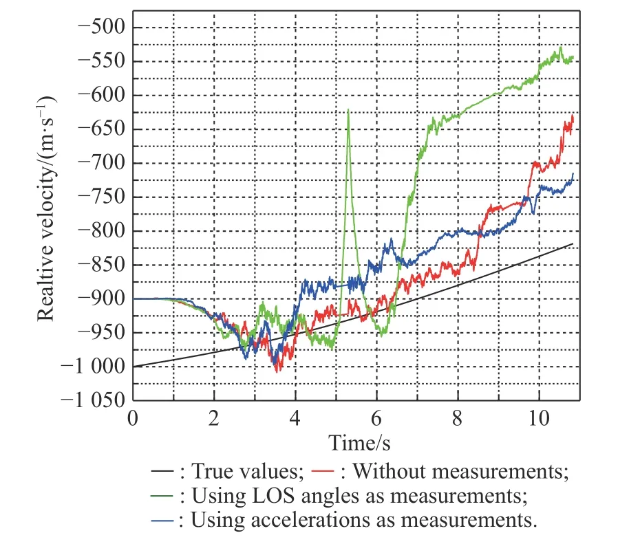
Fig. 24 Simulation of with the CA extended model
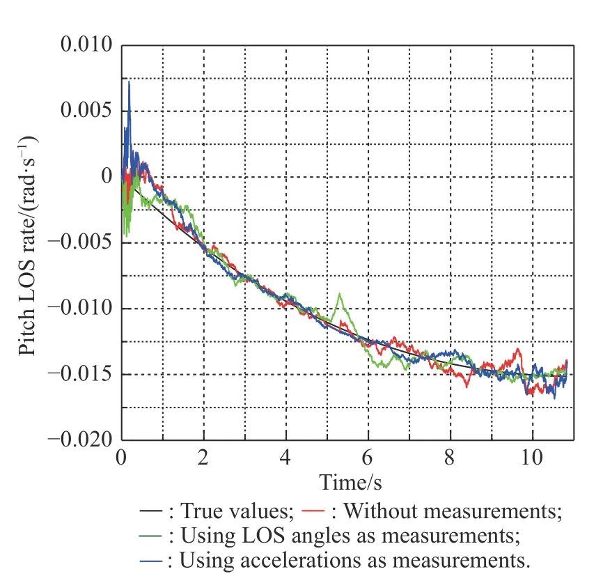
Fig. 25 Simulation of with the CA extended model
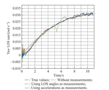
Fig. 26 Simulation of with the CA extended model
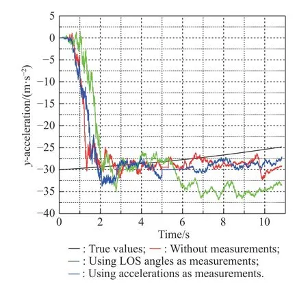
Fig. 27 Simulation of aty with the CA extended model
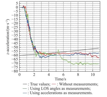
Fig. 28 Simulation of atz with the CA extended model

Table 8 Summary of specific data in Figs. 23−28
From Figs. 23-28 and the specific data in Table 8, we know that due to the change of target acceleration at a constant speed, the filtering effects of the existing methods are all affected, in particular the estimation of relative distance and relative velocity. However, compared with the other two existing methods, the method of using acceleration at the moment of releasing the decoy as measurement has a better filtering effect, which means that the new method still has advantages when the target maneuvers with the CA extension model.
5.2 Target maneuver with singer model
When the target avoids the missile, the maneuvering acceleration may change dispersedly. In this case, the singer model can be used to describe the target maneuvering. As a commonly used target maneuvering model, the singer model assumes that the acceleration of the target is an exponential autocorrelation zero-mean random process. The target acceleration frequency α is used to show the change rules of the target’s acceleration. Assume that maneuvering accelerations in the inertial space are atx, atyand atzrespectively. ωx, ωyand ωzare the noises. According to the singer maneuvering model, the relationship between the noise and the target acceleration is
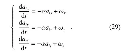
According to the vector derivation equation and coordinate transformation, which we mentioned in Section 3,we can obtain the new state equation of target accelerations:
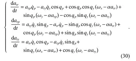
Other state equations are the same as that in (16), and set the same initial conditions for the simulation as that in Subsection 5.1. Set α as 0.2 in the simulation and we design a simplified target maneuver singer model for simulation, in which the target acceleration changes only once before and after releasing the decoy. Table 9 shows several types of simulation conditions with different filtering methods. Figs. 29-34 show the simulation results under the singer model with different methods. Table 10 shows the specific data of these figures.
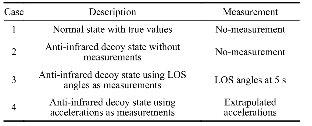
Table 9 Different cases with measurements under singer model
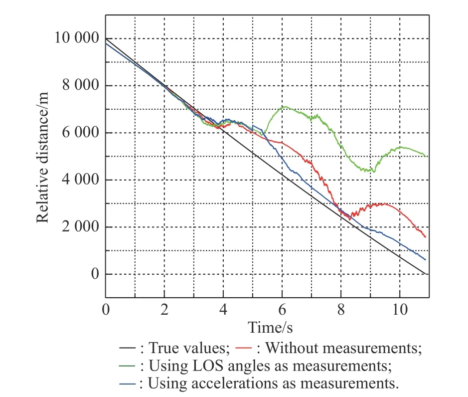
Fig. 29 Simulation of R with the singer model
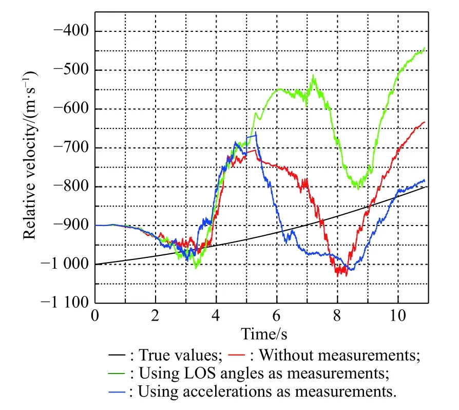
Fig. 30 Simulation of with the singer model
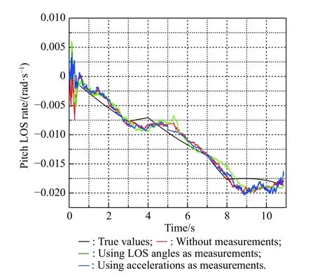
Fig. 31 Simulation of with the singer model
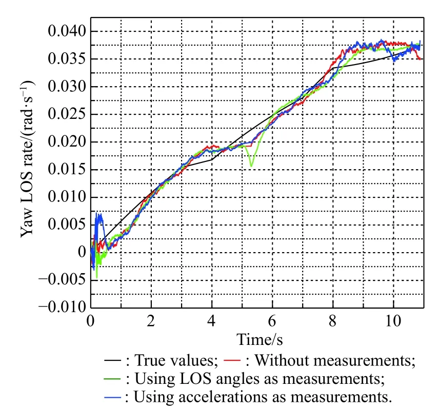
Fig. 32 Simulation of with the singer model
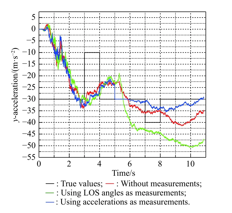
Fig. 33 Si mulation of with the singer model
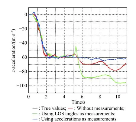
Fig. 34 Simulation of atz with the singer model
From Figs. 29-34 and specific data in Table 10, we know that due to the dispersed changing of target acceleration, the filtering effect is greatly reduced. The estimation of relative distance and relative velocity has large errors. The estimation of the target acceleration becomes divergent. However, compared with the other two existing methods, the method of using acceleration at the moment of releasing the decoy as measurement has a better filtering effect on the estimation of LOS rates and target accelerations, which means that the new method proposed in this paper still has advantages when the target maneuvers with the singer model.Due to the jump change of the target acceleration, the estimation of relative distance and relative velocity fluctuate greatly under all three methods. In comparison, the final estimation error of the new method is smaller than that of the existing method, which also shows the advantages of the new method.

Table 10 Summary of specific data in Figs. 29−34
6. Conclusions
In this paper, the problem of the LOS rate and other guidance information extraction for the roll-pitch seeker under the anti-infrared decoy state is researched. Different methods for guidance information extraction are compared and finally a new method that uses the target’s accelerations as measurements for the filter model is proposed.From the simulation, we can draw conclusions as follows.
The jamming state will cause errors on reconstructed LOS angles. These errors will cause an adverse effect on the missile guidance and control system. To reduce the error, the appropriate method should be used during the jamming state.
The filter model is usually used to extract the LOS rate for the roll-pitch seeker. LOS angles are chosen as measurements for the filter model. If the measurements are inaccurate, the LOS rate extracted by the filter model will be inaccurate, too.
Under the CA maneuvering model, the target’s accelerations can be used as measurements for the filter model.The effect on extracting the guidance information of this new method is better than the existing methods mentioned in Subsection 3.2. Estimation errors will cause inaccurate extraction of the guidance information, but the effect is not serious within the estimation error range of the filter.
Compared with the other two existing methods, the method of using acceleration at the moment of releasing the decoy as the measurement has a better filtering effect on the estimation of LOS rates and target accelerations when the target maneuvers with the CA extended model or the singer model.
The research results in this paper can provide a solution to the anti-infrared decoy jamming problem of the infrared semi-strapdown air-to-air missile. Future work will focus on the problem of anti-jamming and LOS extraction in the case of multi-decoys and random target maneuver.
 Journal of Systems Engineering and Electronics2021年1期
- Journal of Systems Engineering and Electronics的其它文章
- Unsplit-field higher-order nearly PML for arbitrary media in EM simulation
- A deep learning-based binocular perception system
- STAP method based on atomic norm minimization with array amplitude-phase error calibration
- Higher order implicit CNDG-PML algorithm for left-handed materials
- Fast and accurate covariance matrix reconstruction for adaptive beamforming using Gauss-Legendre quadrature
- Multiple interferences suppression with space-polarization null-decoupling for polarimetric array
