Short-range clutter suppression method combining oblique projection and interpolation in airborne CFA radar
HU Yili, ZHAO Yongbo, PANG Xiaojiao, and CHEN Sheng
National Laboratory of Radar Signal Processing, Xidian University, Xi’an 710071, China
Abstract: The airborne conformal array (CFA) radar’s clutter ridges are range-modulated, which result in a bias in the estimation of the clutter covariance matrix (CCM) of the cell under test(CUT), further, reducing the clutter suppression performance of the airborne CFA radar. The clutter ridges can be effectively compensated by the space-time separation interpolation (STSINT) method, which costs less computation than the space-time interpolation (STINT) method, but the performance of interpolation algorithms is seriously affected by the short-range clutter,especially near the platform height. Location distributions of CFA are free, which yields serious impact that range spaces of steering vector matrices are non-orthogonal complement and even no longer disjoint. Further, a new method is proposed that the shortrange clutter is pre-processed by oblique projection with the intersected range spaces (OPIRS), and then clutter data after being pre-processed are compensated to the desired range bin through the STSINT method. The OPIRS also has good compatibility and can be used in combination with many existing methods. At the same time, oblique projectors of OPIRS can be obtained in advance, so the proposed method has almost the same computational load as the traditional compensation method. In addition, the proposed method can perform well when the channel error exists. Computer simulation results verify the effectiveness of the proposed method.
Keywords: airborne conformal arrays (CFA) radar, oblique projection, intersected range space, short-range clutter suppression.
1. Introduction
The conformal array (CFA) antennas can be attached to the surface of the aircraft, greatly reducing the reflection cross section of the aircraft. The stealth capability and target detection capability are enhanced by the larger aperture of the airborne CFA radar [1-3]. The traditional space-time adaptive processing (STAP) technology [4] is an important method to assess the clutter suppression performance of the airborne radar. However, the STAP performance of the airborne CFA radar is limited by the unstable clutter distribution.
Many methods have been proposed to suppress the range-dependence clutter, common compensation-like algorithms such as Doppler warpping (DW) [5], angle-Doppler compensation (ADC) [6], space-time interpolation (STINT) [7], and derivative-based update-like (DBUlike) algorithms such as DBU [7] and modification DBU(MDBU) [8]. The DW method [5] and the ADC method[6] are conventional compensation algorithms. Although these algorithms are easy to be implemented, the improvement performance is sensitive to configuration parameters. The DBU method [7] can effectively suppress the short-range clutter, but requires more training samples and calculations. A two-stage hybrid clutter range-dependence compensation method was proposed in [8].However, owing to the double degrees of freedom of the MDBU method, the MDBU technology is limited by the computational burden. Through the idea of least squares fitting estimation [9], an STINT method was proposed in[10,11], where an interpolation matrix was designed to compensate the clutter data of the training samples to the desired range bin, so as to eliminate the clutter range dependency. There were some improved STINT methods in[12-14]. In [12], a unitary constraint was added to the STINT (UCSTINT) algorithm, which could reduce the fitting loss at the short-range clutter. In [13,14], the idea of space-time separation interpolation (STSINT) method was proposed that the spatial and temporal domains interpolation matrices were solved respectively, but in [14],only the procedure of STSINT was described without the mathematical analysis. As for the application of the STSINT method in the airborne CFA radar, the clutter environment needs to be analyzed from three dimensions[15-17], so the performance of the STSINT method can be further improved.
The projector can be applied in airborne STAP [18-21]. When range spaces of steering vector matrices no longer satisfy the orthogonal complements relationship,the orthogonal projector need be replaced by the oblique projector. In [20], a method of combining the orthogonal projector and DW was proposed for the suppress clutter,but this method cannot suppress the clutter entering from the normal direction of the antenna array, being not suitable for the airborne CFA radar structure. In [21], the elevation dimensional system degrees of freedom were utilized to suppress the short-range clutter by the oblique projector, but the procedure was in the three-dimensional-STAP technology [22].
This paper proposes a joint oblique projection of the intersected range spaces (OPIRS) and STSINT methods for the airborne CFA radar to suppress the short-range clutter. The proposed method firstly pre-processes the short-range clutter by considering the row full rank oblique projector onto the interested range space, and then uses the STSINT algorithm to compensate clutter ridges to the desired clutter ridge. The oblique projector can be obtained in advance. In addition, the OPIRS also has good compatibility and can be used in combination with many existing methods.
The rest of this paper is organized as follows. The antenna model and clutter characteristic of CFA are described in Section 2. Then, the proposed method is given in Section 3. Section 4 analyzes the performance of different methods with simulation data. Summarizing remarks are given in Section 5.
2. Clutter model of airborne CFA radar
2.1 Antenna model of CFA
The CFA antennas location change of different elements is nonlinearity owing to antennas attached to the surface of the airborne radar, and the gain of every element needs to be considered.
Any surface of the three-dimensional space can be denoted as F(x,y,z)=0, and assume that the nth element coordinate can be denoted as (xn,yn,zn), wheren=1,2,···,Ne, Neis the number of all elements. The normal direction of the nth element is

where the operation of Fx, Fyand Fzis the partial derivation of x , y and z, respectively.
Fig. 1 is the aircraft semi-paraboloid CFA with curve formulate expressed as z=x2+y2, where blue points are the location of elements, green arrows indicate the normal of elements, red points are the equivalent phase center of all elements after the subarray synthesis in Subsection 2.2.
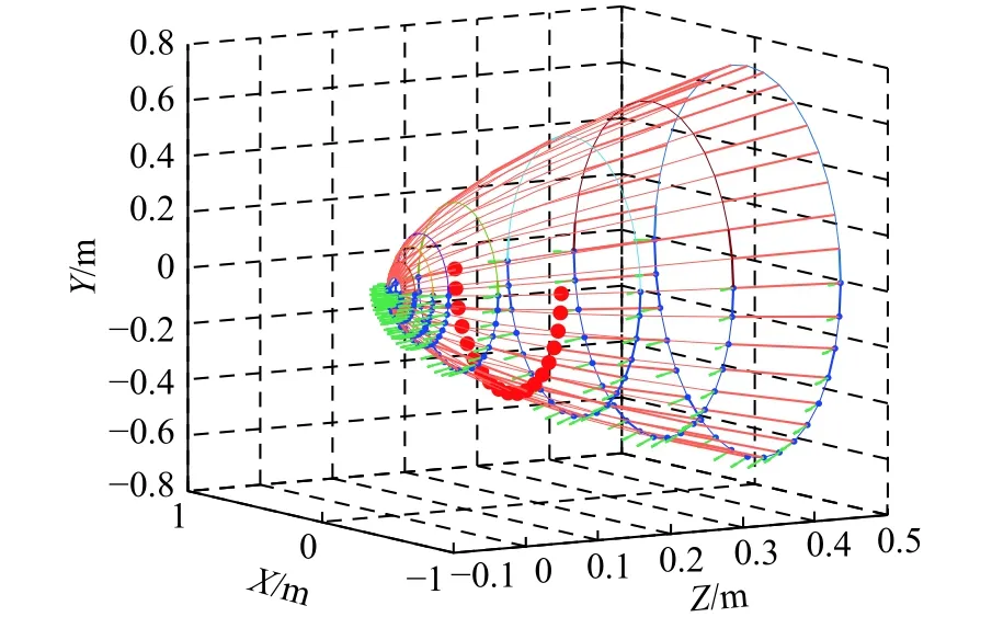
Fig. 1 Antenna model of CFA
The gain of every element is related to the element pattern. Assume that all elements have the same cosinesquared pattern and the nth element can be denoted as

where gbis the backlobe attenuation, g0is the peak element gain, θnullis the beamwidth between the nulls, and βnis the angle between the nth elements’ normal and the main beam azimuth angle.
2.2 Clutter model of CFA
The clutter model of the airborne radar is described in Fig. 2.
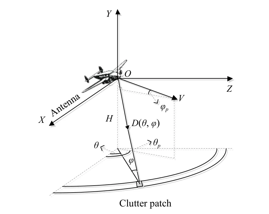
Fig. 2 Clutter model of airborne CFA radar
In Fig. 2, H is the platform height, the equivalent antenna array is along the X-axis, θ is the azimuth angle between the echo of the clutter patch and the X-axis,φ is the elevation angle of the clutter patch,is the azimuth and elevation angles of aircraft velocity respectively, and the clutter patches’ unit vector is D(θ,φ)=where the notation [·]Tis the transpose operation.
If the radius of the earth is taken into account, the elevation angle can be denoted as

where REis the earth’s radius, R is the range between the aircraft and the clutter patch. The spatial snapshot ve/sin the l th range bin and the n th clutter patch can be denoted as


where g(θn,φl) is the cosine-squared pattern gain of all elements in (5),is needed in(2) and (5), me/nedenotes the coordinate vector of the neth element, ss(θn,φl) denoted in (6) is a spatial steering vector, and ⊙ is the Hadamard product.
The subarray synthesis affects the spatial steering vector of weighted elements. Assume that Neelements are synthesized into N subarrays and the subarray synthesis transformation matrix T ∈CNe×Nis denoted as

where Qnis the number of subarrays containing the neth element.
The spatial steering vector of subarrays is denoted as

where the notation [·]His the conjugate transpose operation.
The Doppler steering vector describes the phase change between pulses. Assume that the Doppler frequency is denoted as


where K is the number of coherent pulses, and Tris the pulse repetition period. The space-time steering vector in Fig. 2 can be denoted as v=vt⊗vs, where the notation ⊗is the Kronecker product. Clutter data of the l th range bin are denoted as

where Naindicates the number of ambiguous ranges,Ncindicates the number of clutter patches over an iso-range bin, n is the Gaussian white noise vector, αa,iis the ith clutter patch’s complex amplitude of the ath ambiguous range.
We usually consider the aircraft velocity to be parallel to the ground, that is φp≈0. The normalized Doppler frequency in the CFA three-dimensional space is denoted as


where Fsx=cosθcosφ , Fsy=sinθcosφ , Fsz=sinφ, fr=1/Tr. According to (12), the CFA clutter characteristic needs to be researched from Fd−Fsx−Fsy−Fszfour-dimensional space [16]. Clutter ridges of different range bins are shown in Fig. 3.
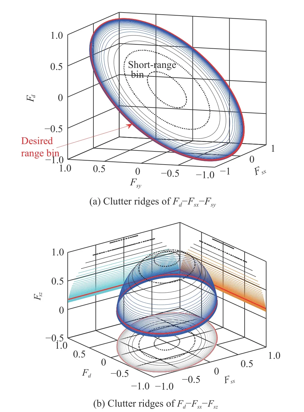
Fig. 3 Clutter ridges of CFA
In Fig. 3, the red line is the desired clutter ridge, the black lines are short-range clutter ridges and the black dotted lines are the clutter with a height close to the platform. Obviously, the near platform height clutter varies greatly with the range.
According to Fig. 3, Fsx, Fsyand Fszcan decide the change of Fd, leading to the clutter heterogeneous characteristic of the airborne CFA radar. As the elevation angle increases, the change of the clutter ridge becomes more and more stable, and fortunately, most targets exist at long-range. Therefore, the short-range clutter can be suppressed without destroying the target.
3. Combining oblique projection and STSINT
3.1 Analysis of STSINT method
The STSINT method [13,14], separately, utilizes spatial and temporal interpolation algorithms to approximate the spatial and temporal steering vectors of the training samples to the desired range bin, to ensure that the training samples of the estimating clutter covariance matrix(CCM) is close to the independent identical distribution(IID) after the interpolation operation.
The ith clutter patch is denoted aswheredenotes the floor operation. The elevation angle of the lth range bin is φl, the clutter space-time matrixis denoted as

The elevation angle of the desired range bin is φd, the desired clutter space-time matrixis denoted as

The STINT method is denoted as

where the notation ‖·‖Fis the Frobenius norm. The solution of (15) is given by

where † denotes the pseudo-inverse. Owing to Nc≫KN[10], obviously,whereis the rank operation. Then,andcan be denoted together by KN linear independent vector groups whereis the range space. Therefore, it is possible to use the information that the columnvectors ofandare linear correlation to reduce the data dimension of the estimated interpolation matrix. Meanwhile, spatial and temporal interpolation matrices can be processed, respectively. Further, the interpolation matrix of the STINT method can be separately solved in (17) and (18).


The interpolation matrix of the STSINT method is denoted as

The output data Zlafter interpolating is denoted as

where l=1,2,···,L−1, L is the number of training samples. After the interpolation operation, the CCM is denoted as

The STSINT method is a least square fitting method[23], in which the loss of estimating the CCM may be severe when clutter echoes have a poor space-time coupling relationship, for example, when range bins include platform height. According to Fig. 3, the clutter ridge between the short-range and the desired range is significantly different. The clutter spatial and temporal steering vector matrices of short-range bins are difficult to interpolate into the desired range bin.
3.2 The proposed method
The proposed method of combining the oblique projection and STSINT, firstly, pre-processes the short-range clutter by considering the row full rank oblique projector onto the desired range spaces, and then uses the STSINT method to compensate clutter ridges.
The basic knowledge of the oblique projection is described in [23-26]. Assume that the spatial steering vector matrixof the lth range bin can be represented as

The spatial steering vector matrixof the desired range bin can be represented as


where r′and θ′are the radius of the antenna ring and the azimuth of the antenna, respectively. Because φl≠φd, we can get the same column vector 1Ninandwhen cos(θ′−θ)=0 , where 1Nis a vector whose elements are all 1. Hence, as long as the condition θ′−θ=±π/2 is satisfied, we can confirm thatfurther,andare the intersected range spaces in the airborne CFA radar, as shown in Fig. 4.
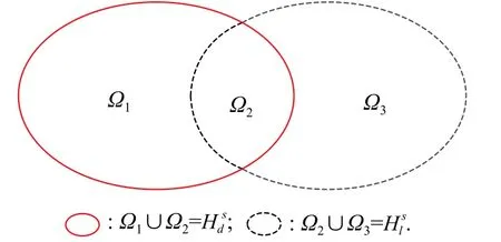
Fig. 4 Range space relationship of
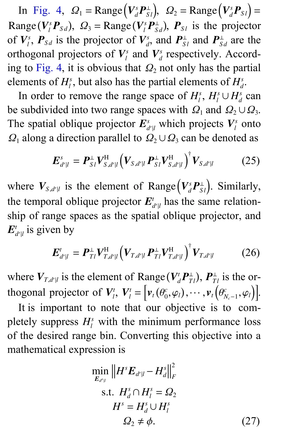
Ω2is determined by system parameters, especially the conformal array manifold and the distance of the clutter bin. The purpose of the cost function is to make the result of Hsprocessed by the oblique projection operator Ed′|ltend to thespace. According to the aforementioned analysis, the solution ofObviously, when Ω2=ϕ in the constraint condition of(27), it is equivalent to the classical orthogonal projection method.
Although the distance range division method applied in(25) and (26) destroys partial space-time coupling characteristics, the heterogeneous clutter with seriously affecting interpolation algorithm performance can be absolutely suppressed, such as the clutter with the near platform height.
The main information of forming the oblique projector is the geometric structure of CFA, the elevation boundary angle φBof the oblique projection area and the elevation angle of desired range bin φd. Therefore, the oblique projector of the lth range bin which can be obtained in advance is given by

According to Fig. 3, we just need to suppress the particular short-range clutter, such as the near platform height range clutter. The elevation angle area of the oblique projection is φl∈[−90°,φB], and then the clutter data after being pre-processed by row full rank oblique projection Ed′|lare

It should be noted that on the one hand, the value of φBcannot be too large, otherwise it will increase the pre-processing workload and destroy the space-time coupling characteristic of the CCM; on the other hand, φBcannot be too small, otherwise it will reduce the suppression performance of the short-range clutter.
In summary, the main steps of combining the oblique projection of the intersected range spaces and STSINT in the airborne CFA radar are as follow:
Step 1Set the elevation boundary angle φB, the desired elevation angle φd, the scalars t′and s′.
Step 2Based on φB, φdand the geometric structure of CFA, we can obtain the oblique projector corresponding to the l th range bin according to (25) and (26).
Step 3If the elevation angle of the lth range bin is φl∈[−90°,φB], and then use the oblique projector in (29)to pre-process clutter data, otherwise skip to Step 4.
Step 4The scalars t′and s′are used to design the interpolation matrixin (17)-(19), and the clutter data after being interpolated are
Step 5According to Zl, the CCM R is obtained in(21).
In Step 3 and Step 4, the operational processes are carried out at the lth range bin, therefore, we can conveniently judge whether φlis in [−90°,φB] before executing Step 4.
The extended factored approach (EFA) [27] is an effective method to suppress the residual clutter. If the Doppler bin k is to be detected, the CCM after the Doppler domain processing is
where is an N-dimensional unit matrix. The spatial steering vector can be represented as


The improvement factor (IF) can be utilized to reflect the performance of different methods. The IF can be represented as

where the SCNRois the output signal-to-clutter-pulsenoise ratio, the S CNRiis the input signal-to-clutter-pulsenoise ratio, CNR is the input clutter-to-noise ratio,is the noise power, and vts=vt(fk)⊗vs(θ0,φ0), in which(θ0,φ0)is the beam direction of transmitting.
4. Simulation results
System parameters of the airborne CFA radar are shown in Table 1.
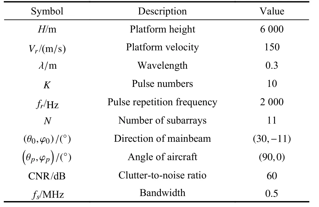
Table 1 System parameters
The geometric structure of CFA is shown in Fig. 1. Assume that the cosine-squared patterns of all elements have θnull=180°beamwidth, gb=−35 dB backlobe attenuation, φBcorresponds to the elevation angle of the 36th range gate,and
In order to simply represent different methods, the method of combining the oblique projection of the intersected range spaces and STSINT is referred to as OPIRSSTSINT, and the method of combining the oblique projection of the intersected range spaces and STINT is simply referred to as OPIRS-STINT, the proposed method in [8] is called ADC-MDBU, the proposed method in[12] is called UCSTINT, and the conventional method in[4] is called sample matrix inversion (SMI).
In order to verify the effect of the oblique projection method on the short-range clutter suppression in the airborne CFA radar, the range-Doppler images are given here after EFA processing in Fig. 5. Among them, the clutter data have three range ambiguities, and the clutter data of the range gates from 20 to 250 are simulated.
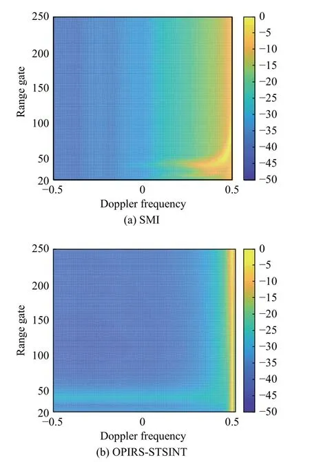
Fig. 5 Range-Doppler performance
We can see that compared with the OPIRS-STSINT method, the range-Doppler performance of SMI is poor,especially at the short-range. In particular, according to Fig. 5(a), the Doppler frequency of the short-range clutter is sensitive to range and is seriously ambiguous in the main-lobe clutter region. Meanwhile, it can be clearly seen from Fig. 5(b) that the OPIRS-STSINT method can show excellent performance in suppressing the shortrange clutter of the airborne CFA radar by the oblique projection in the presence of range ambiguous.
The target is at the 104 range gate which is also the desired range gate. The clutter capon power spectrum [4]comparison of SMI, OPIRS-STSINT, and OPIRS-STINT methods are shown in Fig. 6.
Fig. 6 is obtained when the elevation angle is fixed on φ0. The power spectrum of SMI is diffused by the heterogeneous clutter data, and the OPIRS-STSINT and OPIRSSTINT methods have the same performance of the power spectrum, however, the computational burden of OPIRSSTINT is heavier.
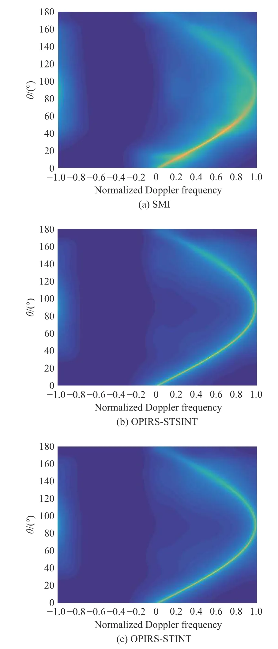
Fig. 6 Power spectrum at φ0
The STAP weight vector represents the optimal performance of the airborne radar. The STAP weight vector can be denoted as

where v is the space-time steering vector.
Fig. 7(a) is the IF performance of the STAP by utilizing the optimal weight vector in (34), and Fig. 7(b) is the IF performance of the EFA-STAP. The 5% channel error is added in training samples.
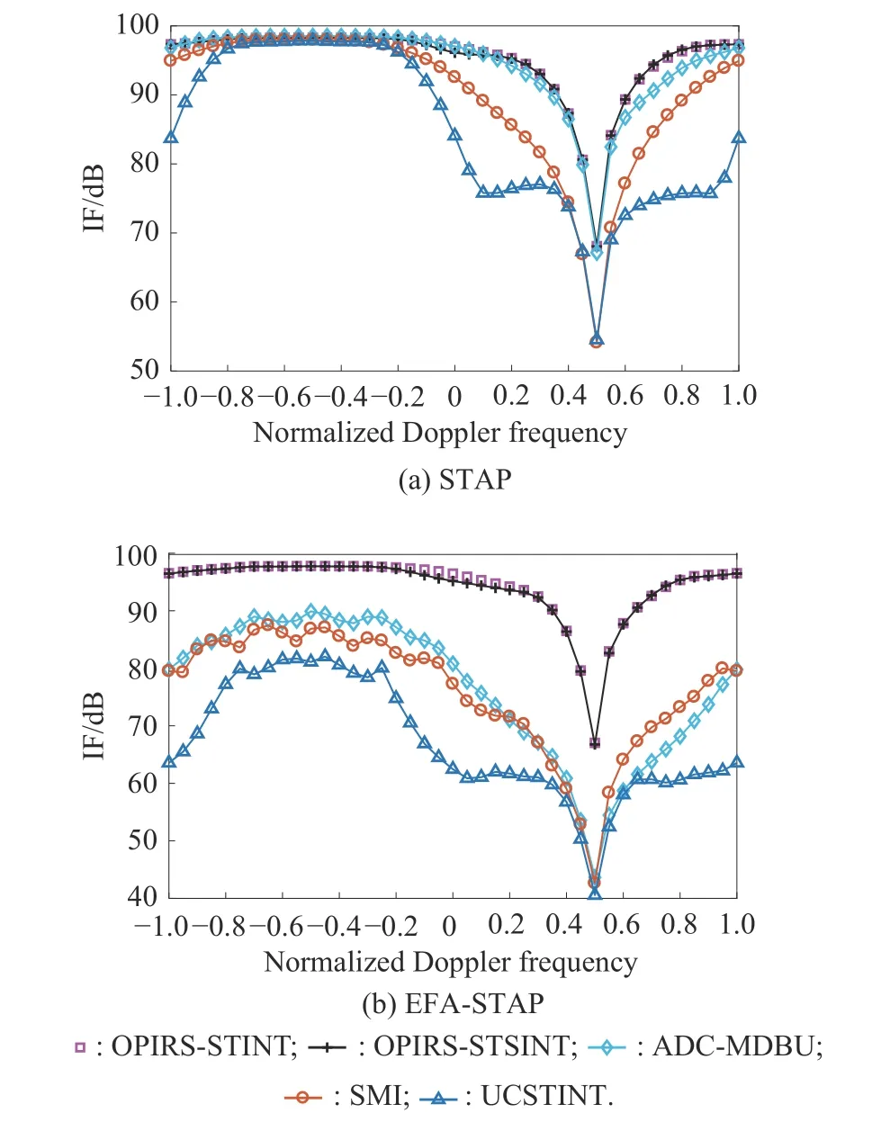
Fig. 7 IF performance
In Fig. 7(a), attributing to the fact that the ADCMDBU method is sensitive to the system degree of freedom, the STAP of the ADC-MDBU method has a better performance than its EFA-STAP, but in practice it is difficult to obtain enough training samples and execute heavy calculations. The performance of the UCSTINT algorithm is reduced by the unitary constraint added in interpolation matrix. The SMI performance in Fig. 7(a) can verify that the training samples are not IID.
According to Fig. 7, the OPIRS-STSINT method has the same IF performance as OPIRS-STINT. Further, we can see that the OPIRS-STSINT method’s EFA-STAP performance is the same as its STAP performance according to Fig. 7, in other words, the clutter data after the oblique projection operation are closed to IID. Therefore, the proposed method can effectively suppress the short-range clutter even if the channel error exists.
It is important to note that the interpolation algorithm has certain ability to deal with errors environment, but when training samples have the short-range clutter especially near the platform height, the robust performance of the interpolation algorithm becomes particularly poor, at the same time, OPIRS can suppress the clutter near the platform height, so the OPIRS-STSINT still performs well when there is 5% channel error. However, the robustness of the OPIRS itself is limited. When there is a large channel error, the performance will be reduced accordingly, therefore how to improve the robustness of the OPIRS method is the focus of the future research.
Table 2 shows the IF of OPIRS-STSINT and OPIRSSTINT when the clutter echo range corresponding to φBtakes different values.
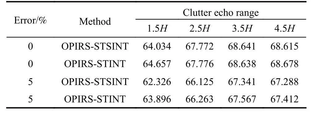
Table 2 Target IF value dB
The corresponding relationship between the clutter echo range and φBrefers to (3). When the error is fixed,as the clutter echo range increases, the target IF value tends to increase, but when the clutter echo range increases to a certain extent, the IF value no longer increases or even decreases, indicating that φBcorresponding to the clutter echo range cannot be too small or too large.
Although the oblique projection operator of the OPIRS method is a preprocessing process and does not increase the amount of calculation, it increases the number of multiplications when the OPIRS-STSINT method processes clutter data in real time. Therefore, it is necessary to study the required time to generate the clutter when the clutter echo range is different. In Fig. 8, the OPIRS processing time chart for the clutter data is shown as the clutter echo range changes.
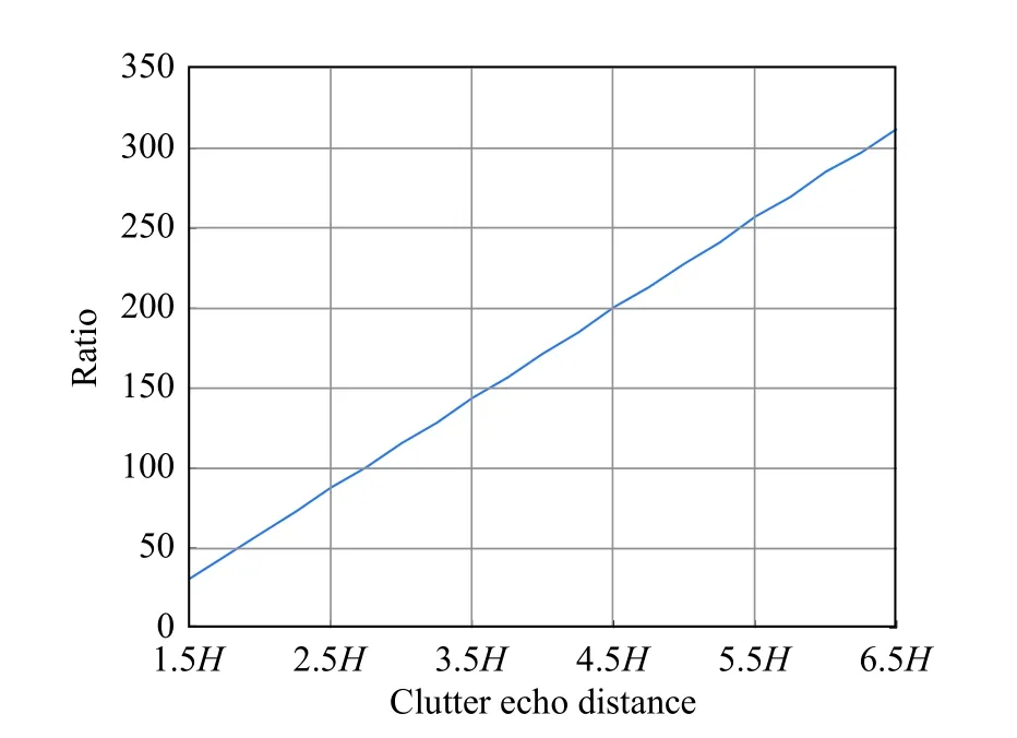
Fig. 8 OPIRS processing time
In Fig. 8, the Y-axis means the ratio of the time used by OPIRS to process the clutter data and the time used when OPIRS is not used to process the clutter data. From Fig. 8,we can see that the clutter echo range of OPIRS is proportional to the time used to process clutter data. Through the analysis of Table 2 and Fig. 8, the clutter echo range can be selected within the range of 2.5 H and 3.5 H,which can save the calculation amount of the OPIRS part in real-time processing and also obtain a more ideal target IF value.
Table 3 shows the comparison of EFA-STAP on the computational burden.
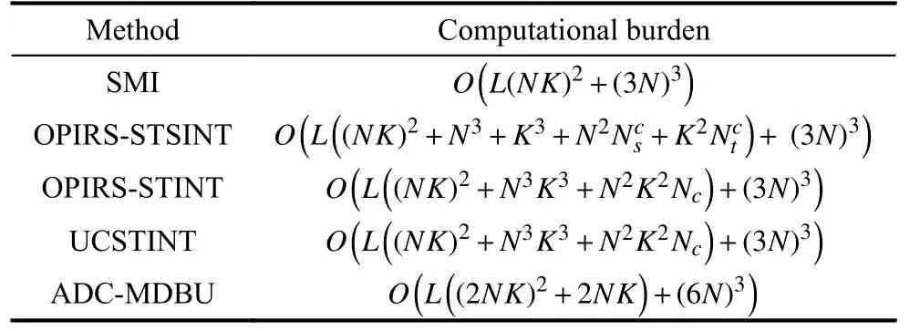
Table 3 Computation burden
The STINT method costs larger computational burden on forming the interpolation matrix than the STSINT method. According to Table 3 and Nc≫NK, the order of computation in different methods is SMI<OPIRS-STSINT<ADC-MDBU<UCSTINT ≈ OPIRS-STINT. Obviously, the OPIRS-STSINT method has a less computational burden and a better IF performance.
It is worth noting that the key of this method is to overcome the short-range clutter of the airborne CFA radar by using OPIRS. Although OPIRS belongs to one of the subspace projection methods, if the oblique projection is used directly, it still cannot solve the short-range clutter in the CFA. Fortunately, the OPIRS has a good compatibility, and it can be used in combination with compensation-like algorithms such as ADC, DW, STINT, and DBUlike algorithms such as DBU and MDBU. Fig. 9 and Fig. 10 respectively describe the combination of the IF performance of OPIRS and the ADC and DBU methods under EFA processing. In order to make ADC and DBU methods have the normal performance, the original clutter data do not include the clutter near the height line.
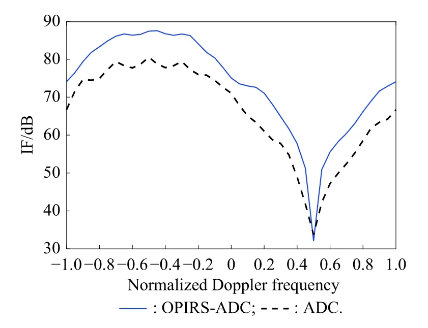
Fig. 9 Comparison of OPIRS-ADC and ADC
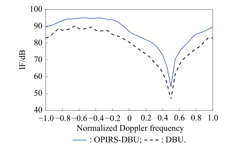
Fig. 10 Comparison of OPIRS-DBU and DBU
According to Fig. 9 and Fig. 10, it can be seen that the performance of the OPIRS combined with the ADC and DBU methods is better than the performance without the combined processing, that is because the main work of the OPIRS is to suppress the clutter at the short-range clutter especially near the height line, but the compensation-like algorithm is to map the clutter spectrum at the short-range to the clutter spectrum line at the desired range, and the DBU-like algorithm assumes that the sample data change with the clutter echo range, and then the samples are weighted by the changed clutter echo to suppress the short-range clutter. Obviously, the OPIRS and these methods are not contradictory, and can be used in combination to improve the suppression ability of the short-range clutter.
5. Conclusions
The clutter characteristic of the airborne CFA radar involves three dimensional spaces, leading to range spaces of different range bins are no longer disjoint. For the first time, we propose a new idea for suppressing the shortrange clutter, specifically by utilizing the oblique projection of the intersected range spaces to make the shortrange clutter spatial and temporal steering vector matrices onto the desired range bin.
The idea of the oblique projection of the intersected range spaces is effectively applied for the airborne CFA radar, and the performance loss of the interpolation method can be reduced when the short-range heterogeneous clutter is in training samples. In fact, the range area of the oblique projection operation only needs to include the platform height where the severe heterogeneous clutter mainly exists. The basic information for forming oblique projectors can be obtained in advance, which allows it to play an important role in real-time processing.
The robust performance of the proposed method is decided by the combination impact of the oblique projection and STSINT, and when severe heterogeneous clutter is suppressed by oblique projectors, the residual clutter can be considered as IID, where the STSINT algorithm can perform well. However, the robustness of the OPIRS is limited, and the further research is needed on how to increase the robustness of the OPIRS.
In addition, the OPIRS also has good compatibility and can be used in combination with many existing methods,such as compensation-like algorithms and DBU-like algorithms. The combination of these methods not only solve the failure problem of classical compensation-like algorithms and DBU-like algorithms when the short-range clutter contains clutter near the height line, but also complements the classical methods to further improve the ability to suppress the short-range clutter. Finally, simulation results verify the performance of the proposed method.
 Journal of Systems Engineering and Electronics2021年1期
- Journal of Systems Engineering and Electronics的其它文章
- Unsplit-field higher-order nearly PML for arbitrary media in EM simulation
- A deep learning-based binocular perception system
- STAP method based on atomic norm minimization with array amplitude-phase error calibration
- Higher order implicit CNDG-PML algorithm for left-handed materials
- Fast and accurate covariance matrix reconstruction for adaptive beamforming using Gauss-Legendre quadrature
- Multiple interferences suppression with space-polarization null-decoupling for polarimetric array
