An approach of motion compensation and ISAR imaging for micro-motion targets
WANG Yong, ZHOU Xingyu, LU Xiaofei, and LI Yajun
1. School of Electronics and Information Engineering, Harbin Institute of Technology, Harbin 150001, China;2. Jiuquan Satellite Launch Center, Jiuquan 732750, China;3. Shanghai Radio Equipment Research Institute, Shanghai 201109, China
Abstract: Inverse synthetic aperture radar (ISAR) imaging of the target with the non-rigid body is very important in the field of radar signal processing. In this paper, a motion compensation method combined with the preprocessing and global technique is proposed to reduce the influence of micro-motion components in the fast time domain, and the micro-Doppler (m-D) signal in the slow time domain is separated by the improved complex-valued empirical-mode decomposition (CEMD) algorithm,which makes the m-D signal more effectively distinguishable from the signal for the main body by translating the target to the Doppler center. Then, a better focused ISAR image of the target with the non-rigid body can be obtained consequently. Results of the simulated and raw data demonstrate the effectiveness of the algorithm.
Keywords: inverse synthetic aperture radar (ISAR), micro-Doppler (m-D), motion compensation, complex-valued empiricalmode decomposition (CEMD).
1. Introduction
Inverse synthetic aperture radar (ISAR) is one of the most important development directions in the radar imaging,which can generate the two-dimensional (2-D) image of the non-cooperative target by utilizing the relative motion of the target and the radar [1]. The motion of the target can be decomposed into the translation relative to the radar and the rotation relative to the target center. The latter is required for imaging based on the range-Doppler(R-D) principle, while the former needs to be removed before imaging to achieve separable range and Doppler processing, which is called the motion compensation. The motion compensation can be accomplished in the following two steps. The first is range alignment, which shifts the envelopes so that the same scatterer is at the same range cell; the second is phase adjustment, which compensates for the difference in the initial phase of each echo. After motion compensation, the subsequent azimuth coherent processing can be realized by the R-D algorithm. The high range resolution is achieved by the pulse compression of the wideband signal, and the high azimuth resolution is realized by the frequency analysis. The above process composes the basic processing chain of ISAR imaging formation.
The range alignment methods can be divided into two categories. One is the parametric method, according to the continuity of the target motion, and the other is the non-parametric method, according to the similarity of each envelope. The target translation is modeled as polynomial in the parametric methods [2-5]. In practical imaging systems, the continuity of target motion is often destroyed, which makes the non-parametric methods more widely used. The classic non-parametric methods include the maximum correlation algorithms and the minimum entropy algorithms. The cross-correlation algorithm [1]and the accumulation correlation algorithm [6] are both to find the maximum correlation value of echoes for range alignment, which is effective for most targets and easy to be implemented. The entropy criterion was proposed in[7] as the sharpness measurement [8] of the synthetic envelope for range alignment, where the sum of all aligned envelopes was used as the synthetic envelope. The above methods are all local methods. The concept of the average range profile (ARP), and the sum of all envelopes,were first proposed in [9] and applied to the maximum correlation algorithms. This algorithm, considered a global method, transformed the multidimensional search problem into one-dimensional search optimization by using an iterative structure, and overcame the computational burden, which made it achievable and had a good performance in terms of efficiency and accuracy. This global method could be also applied to minimize the entropy of the ARP by using an iterative structure. The mathematical principle of the iterative structure was detailed in[10]. The global methods [9-11] can effectively avoid the accumulation of misalignment errors for the range alignment and achieve global optimal alignment. However, in the practical imaging process, micro-motion components tend to appear in the target, such as the helicopter, propeller aircraft, jet and so on. For the target with rotating parts, the random burst strong scatterer appears at some range cells due to the high speed rotation of the anisotropic blade. The similarity of the envelopes decreases due to the peak introduced by the micro-motion components,which leads to the unsatisfactory effect of the traditional non-parametric methods. Some preprocessing methods were proposed in [12,13] to suppress the peak and improve the envelopes similarity.
The target can be regarded as a turntable model after motion compensation. A scatterer from the uniform rotating rigid body produces a constant Doppler frequency during the imaging time. Therefore, a well-focused image can be obtained by the R-D algorithm. However, for the target with the non-rigid body, the micro-motion components will generate an additional sinusoidal frequencymodulated (FM) signal besides the single-frequency signal, which is called the micro-Doppler (m-D) [14-18].The m-D signal has a large Doppler bandwidth, which causes the ISAR image of the main body to be shadowed in the Doppler domain. This will bring great difficulties to image interpretation and target recognition. Therefore,separation of the m-D signal is very important in ISAR imaging of the micro-motion target to obtain a well-focused image. According to the literature, several available methods for separating the m-D signal from the multicomponent signal are proposed. The method in [19] based on the chirplet decomposition was used to separate the m-D signal, which relied on the chirp-rate threshold to separate the main body signal and the m-D signal. In [20], a method combined the wavelet transform and the time-frequency (T-F) analysis was applied to the separation of the m-D signal. An adaptive decomposition algorithm complex-valued empirical-mode decomposition (CEMD),whose basis function is selected according to the characteristics of the signal and is not fixed, is also used for the m-D signal separation [21]. The CEMD algorithm achieves good imaging results for both the simulated and raw data. On the other hand, the Radon transform and Hough transform in T-F distribution to detect and separate the m-D signal were proposed in [22,23], respectively. A very subtle method of the m-D signal separation was proposed in [24,25], which was called the L-statistics technique.However, these methods require further research on the validity of the raw data.
In this paper, for the micro-motion target with rotating parts, we propose a novel method for range alignment and improve the processing flow of CEMD imaging. Due to the rotating parts of the micro-motion target, the similarity between envelopes is reduced, which violates the condition of the global range alignment method. The preprocessing is integrated into the global range alignment method, which makes the range alignment process more reasonable. The preprocessing global algorithm improves the range alignment accuracy and the image quality to some extent. Using the CEMD algorithm to separate the m-D signal from the main body signal is equivalent to an adaptive filtering process. The turntable model shows that the main body tends to appear at a low Doppler frequency, and the m-D signal appears at a high frequency,which makes CEMD effectively separate the m-D signal.However, if the target center is not exactly at the center of the Doppler frequency, the part of the target on one side may appear in the region of a higher Doppler frequency, while the m-D signal on the other side may appear in the lower Doppler frequency region. These will result in incomplete separation of the m-D signal and incorrect removal of the main body. Therefore, the target center estimation and translation process before CEMD is required. In this paper, we give a general method for estimating the target center in the ISAR image, which combines with CEMD to avoid the above problems in m-D separation and realize a better performance.
The structure of this paper is organized as follows. In Section 2, the radar echoes of the micro-motion target with rotating parts are modelled. After introducing the global range alignment method and preprocessing the method, the novel preprocessing global range alignment algorithm are proposed in Section 3. The results of the raw data based on different range alignment methods are also given here to verify the performance of the proposed method. In Section 4, the flow of the improved CEMD algorithm is proposed. The experimental results of the simulated data and the raw data are given in Section 5. Finally,we make a conclusion in Section 6.
2. Signal model and m-D analysis of micromotion target with rotating parts
The scatterer model can be applied to radar imaging to obtain a simplified form of the target echo. After motion compensation, the movement of the micro-motion target with rotating parts can be divided into two parts, the main body and the rotating parts. The difference between them is that the rotating parts rotate at a high speed besides all the motions of the main body. Without loss of generality,the scatterer model of the target is assumed to be unchanged during the imaging time, and the movement of the micro-motion scatterer does not exceed a range cell. The geometry of the target turntable model is shown in Fig.1.XOY and X′O′Y′represent the main body and the rotating parts coordinate system, respectively. The main body of the target rotates uniformly around the center O with the angular velocity ωO, such as scatterer A with radius RA. In addition to the above-mentioned motion, the rotating parts rotate at a high speed around the center O′with the angular velocity ωO′, such as scatterer B with radius RB.
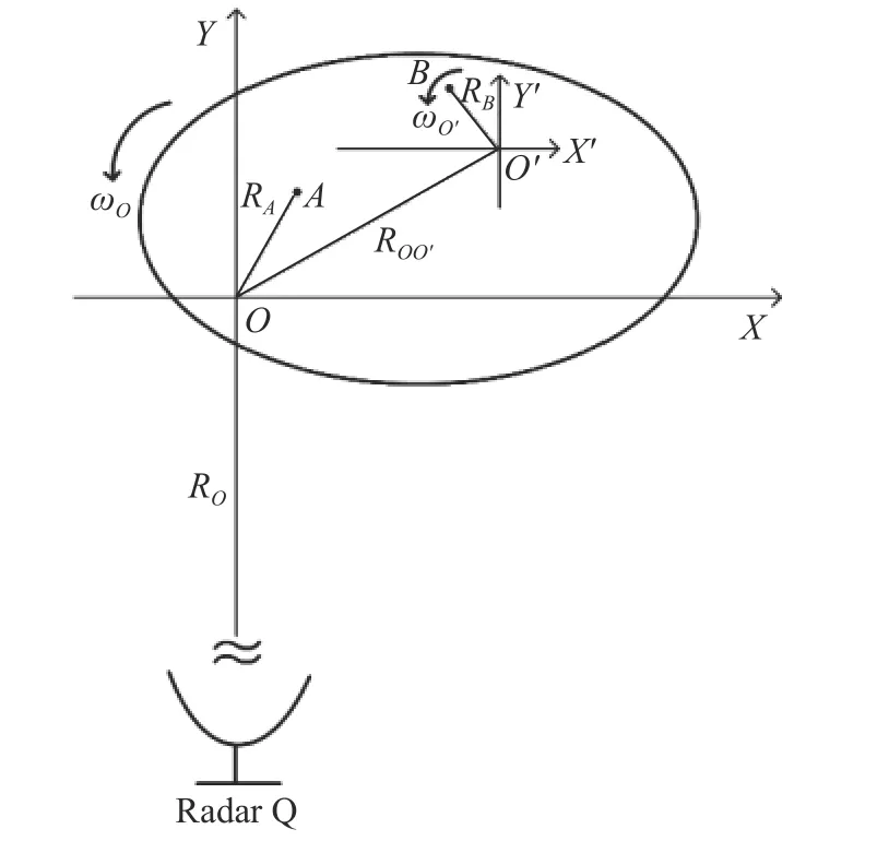
Fig. 1 Imaging geometry for micro-motion target
In the practical radar system, in order to meet the requirements of both transmit power and range resolution, a linear frequency modulation (LFM) signal is transmitted and pulse compression processing is used. The expression of the signal is

where

The received signal after dechirping can be expressed as
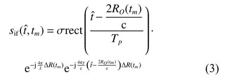
where σ is the reflection coefficient of the scatterer, c is the light speed, λ is the wavelength of the transmitted signal, and ∆ R(tm)=R(tm)−RO(tm) is the distance between the scatterer and the reference point. R(tm) and RO(tm) are the distance between the radar and the scatterer, and the distance between the radar and the reference point, respectively.
Apply Fourier transform (FT) based onin the fast time domain on (3) to complete the pulse compression, and the range profile can be obtained:

In the fast time domain, the reflection coefficient of the scatterer on the rotating parts is flash. Because the anisotropy of the rotating parts makes the reflection characteristics of the scatterer time-varying, the random burst strong scatterer may appear at the range cells in some range profiles, which seriously affects the similarity between the adjacent envelopes. Fig. 2 shows two adjacent range profiles from the raw data of the micro-motion target. It can be seen that Fig. 2(a) and Fig. 2(b) have some similarities, but Fig. 2(b) has a peak at the 144 range cell. As the envelope is aligned, such echoes will produce jump errors that affect the accuracy of the range alignment.
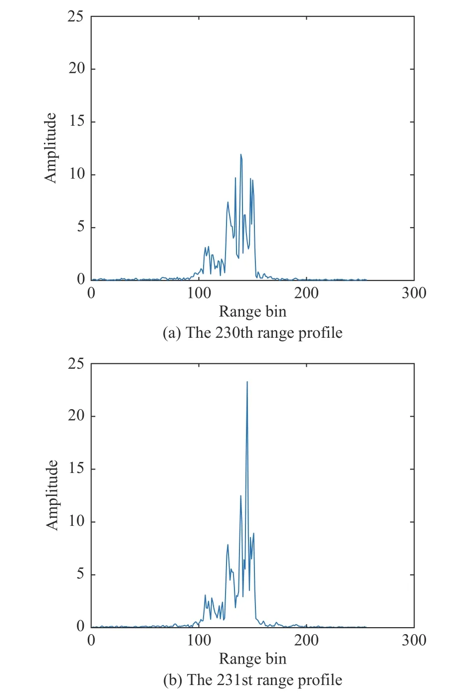
Fig. 2 Range profile of micro-motion target
Using Taylor series expansion, the distance between the scatterer A and the reference point O can be expressed as

where RO(tm)≫RA, and θAis the initial angle of the scatterer A in XOY . The distance between the scatterer B and the reference point O can also be approximated as

where RO(tm)≫ROO′, RO(tm)≫RB, θOO′and θBare the initial angles of O′and B in XOY and X′O′Y′, respectively.
During the imaging time, small angle approximation can be assumed for the main body, which results in that sin(ωOtm)≈ωOtmand c os(ωOtm)≈1. The Doppler frequency introduced by the main body can be obtained by the derivation of phase:

However, the rotating parts might rotate many cycles during the imaging time, so the above small angle approximation is not satisfied. The Doppler frequency introduced by the rotating parts can be written as

In the slow time domain, it can be shown that the scatterer of the main body produces a constant Doppler frequency, which can be analyzed by the R-D algorithm to obtain the ISAR image. For the rotating parts, the scatterer produces an additional sinusoidal FM signal, called the m-D signal. After performing FT, the single-frequency signal from the main body is shadowed by the m-D signal with the large bandwidth. Fig. 3 shows the m-D signal in the raw data. Fig. 3(a) is the imaging result with the R-D algorithm. It can be seen that the m-D signal appears in the 134th and the 144th range cells where the propeller is located, and the signal shadows the main body in the Doppler domain. Observing the T-F distribution of the 144th range cell signal, as shown in Fig. 3(b), it can be found that there are more high frequency interferences in addition to the low frequency components from the main body. However, the m-D signal does not present the sinusoidal FM distribution as theoretically analyzed. The reason for this was preliminary analyzed in [26], when the range of the signal frequency were too high or the radar pulse repetition frequency (PRF) was not high enough,the m-D signal as a sinusoidal curve pattern in the T-F spectrogram would become hardly to identify [26]. In addition, when the movement of the micro-motion scatterer exceeds a range cell, the sinusoidal FM signal is no longer complete. For the above reasons, the m-D signal appears in the pattern shown in Fig. 3, and the further research is needed.
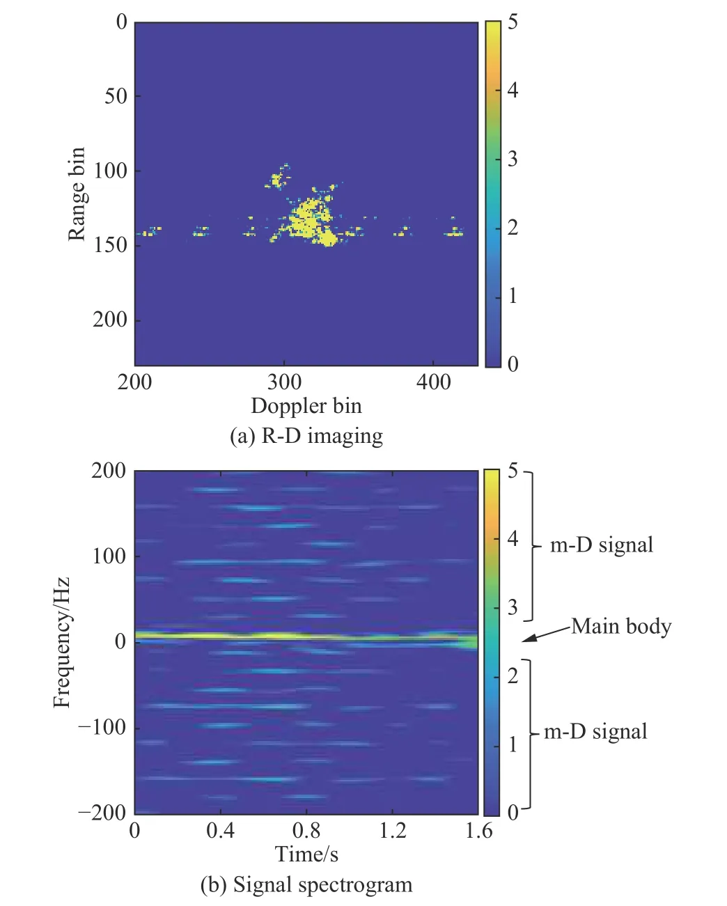
Fig. 3 R-D imaging result of micro-motion target and the spectrogram of the 144th range cell signal
In this paper, the raw data are from the propeller aircraft AN-26 which is considered as a typical micro-motion target with rotating parts.
3. Preprocessing global range alignment algorithm for micro-motion target
In this section, we propose a preprocessing global range alignment algorithm, which is more suitable for the micromotion target.
3.1 The minimum entropy algorithm [10]
The classic global method as a non-parametric method exploits the similarity of the envelopes. When all envelopes are aligned, the peaks and valleys will be matched,and the ARP, the sum of the envelopes, has the greatest sharpness. On the contrary, if the envelope is not aligned,the ARP tends to be uniform. Thus, the entropy of the ARP can be used to measure the sharpness and indicate the quality of the range alignment.
Let p(n, m) be the envelope of the range profile after pulse compression, where n is the range cell and m is the number of echoes.
The ARP is defined as the sum of all envelopes:

where ∆M=[∆(1),∆(2),···,∆(M)], and ∆(m) is the offset of the mth envelope, and M is the total number of echoes.
With entropy as the criterion for sharpness, the entropy of the ARP can be written as

Since E is a function of ∆M, this optimization problem requires M dimensional search, which may be inefficient and unrealizable. The search process can be replaced by an iterative structure and more derivation details can be found in [10]:

The correlation operations in the iterative structure are very common in the maximum correlation algorithms, revealing the connection between the maximum correlation algorithms and the minimum entropy algorithms. The global minimum entropy algorithm is a correlation method by usingas the reference envelope, and the global correlation method is an iteration process by using the contrast as the sharpness measurement.
Specifically, in each iteration process, the correlation function of each envelope and the reference envelope is calculated. The position of the maximum value in the correlation function is taken as the offset of the envelope,and the reference envelope is updated according to the current offset at the same time. An iteration process ends with all envelopes completing the translation. At each iteration, the entropy of the ARP is measured, and the above processing steps are iteratively executed until the entropy stops decreasing. In order to simplify the implementation,the update of the ARP offset can be performed after an iteration ends, that is, the ARP does not change during an iteration, and good convergence can be ensured.
For (11), the convolution between the logarithm of the ARP and each range profile can be efficiently implemented by using the fast Fourier transform (FFT) [10],thereby reducing the calculation complexity of the iterative structure to O (KN).
3.2 Preprocessing global range alignment algorithm
As mentioned above, an important prerequisite for minimizing the entropy of the ARP is the strong similarity between envelopes. It is often satisfied in ISAR imaging of the target with the rigid body, where the reflection characteristics of the targets fluctuate very little during the imaging time. However, for the micro-motion target,this condition needs to be reconsidered. Due to the appearance of the peak in the range profile, the similarity of the envelope is greatly reduced. Fig. 4 shows the envelope correlation between the raw data of the target with the rigid body and the non-rigid body. After preprocessing, the correlation of the envelope is also shown.The correlation coefficient of the envelopes p1and p2is defined as
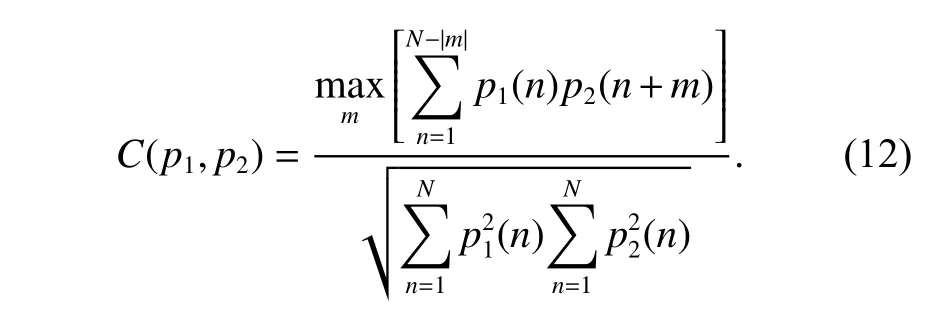
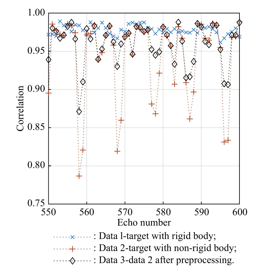
Fig. 4 Envelopes correlation between raw data of the target with rigid body, the target with non-rigid body, and the target with nonrigid body after preprocessing
It can be found that the envelope correlation of the rigid body target is high, generally above 0.96. The envelope correlation of the non-rigid body target is highly fluctuating, and when random peak appears, the correlation is significantly weakened. Through the preprocessing, such as amplitude limit, the correlation between envelopes can be effectively improved, and the fluctuation of correlation can be reduced.
Based on this analysis, we hope to perform appropriate preprocessing before the global envelope alignment for the micro-motion target to improve the envelope similarity. On the one hand, the preprocessed envelopes are used to calculate the ARP and obtain the best alignment result after removing the random peak. Minimizing the entropy of the ARP becomes more effective due to the improved similarity of the envelopes. On the other hand,the jump errors are eliminated when the current envelope after preprocessing is compared with the reference envelope. Therefore, the accuracy of range alignment can be improved.
The amplitude limit as a mean of preprocessing can be obtained by


According to the dynamic range, it can be judged that the range profile is affected by the micro-motion components, that is, when the dynamic range is small, the random peak is not included in the envelope. Therefore, we can find the appropriate threshold level in the envelopes with a smaller dynamic range, which represent the main body of the target. Sort the dynamic range of the envelope

and select the maximum value of the first 20 envelopes with a small dynamic range as the amplitude threshold

which is used to limit the amplitude of other envelopes,especially those with random peak. The number of envelope 20 is proved to be valid as an empirical value.
The flow chart of the preprocessing global range alignment algorithm for the micro-motion target is shown in Fig. 5. The steps in the flow chart will be specifically described below.
Step 1Initialize the initial envelope offset∆(m)=0, m=1,2,···,M.
Step 2Use amplitude limit for each envelope to obtainwith (13) where the threshold level is determined by (16). Calculate the ARP ofby using the current ∆ (m) and the entropy of the ARP.
Step 3Correlate each envelopewith a reference envelopeto obtain a temporary offset ∆′(m).
Step 4Shift the envelopes and use (10) to obtain the entropy of the ARP with the temporary offset ∆′(m).
Step 5If the entropy of ARP corresponding to the temporary offset ∆′(m) is smaller, update ∆(m)=∆′(m),and repeat Steps 3-5, otherwise stop the iteration and output the current offset ∆ (m).
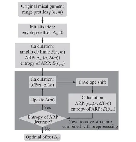
Fig. 5 Flow chart of the proposed method
The calculation complexity of the iterative structure is also O(KN), and the method usually gets good convergence after 5-10 iterations.
3.3 Experiment and performance analysis
ISAR raw data of propeller aircraft AN-26 have been utilized to validate the proposed preprocessing global range alignment algorithm. The results of ISAR imaging with the R-D algorithm based on different range alignment algorithms are shown in Fig. 6. In order to be better display the target, the original image is intercepted.
Fig. 6(a) shows the performance of the cross-correlation algorithm, and Fig. 6(b) performs the rectangular weighted window average in the correlation, while Fig. 6(c)and Fig. 6(d) show the performance of the traditional global minimum entropy algorithm and the proposed method, respectively. The entropy of the ISAR image is calculated to measure the focus of the image based on the conclusion that better focused image results in the smaller entropy. The entropy of the image f(m,n) is defined as
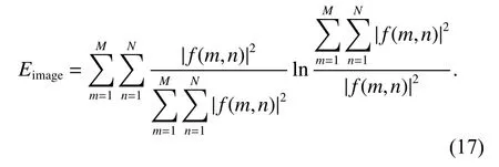
The entropies of the ISAR images are shown in Table 1.From the imaging results, we can see that the cross-correlation algorithm is invalid and the proposed method obtains the minimum entropy of the image. Compared with other images, the image quality of Fig. 6(d) is improved,especially the parts at the arrow in Fig. 6(d) have the best focus. The global methods can further reduce the alignment errors and achieve global optimal alignment compared with the accumulation correlation algorithm. Compared with the traditional global method, the preprocessing of the proposed method can effectively eliminate the peak influence in the range profiles from the micro-motion target and improve the similarity of the echo. When the reflection coefficient of the micro-motion scatterer is strong, the effect will be more obvious. The experimental results show that the proposed preprocessing global algorithm can get the best results.
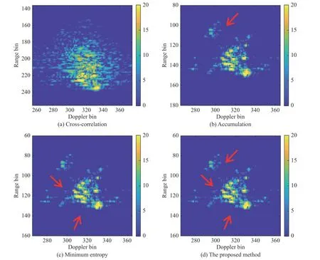
Fig. 6 Imaging results of AN-26 raw data

Table 1 Entropies of ISAR images in Fig. 6
4. m-D separation based on improved CEMD algorithm
In Section 2, we illustrate two problems with ISAR imaging of the micro-motion target. In Section 3, we consider the peak in the range profile in the fast time domain and obtain the best range alignment performance using the preprocessing global algorithm. In this section, we process the m-D signal in the slow time domain. According to the analysis in Section 2, the core of micro-motion target imaging is the separation of the m-D signal. This is to remove the sinusoidal FM signal from the multi-component signal. The CEMD algorithm will be introduced below to solve this problem, which can decompose the signal adaptively. By analyzing the problems that appear in the results of the CEMD algorithm, we propose the improved CEMD algorithm in this section.
4.1 Flow of the CEMD algorithm
The empirical-mode decomposition (EMD) proposed in[21] is a new algorithm of signal decomposition, which decomposes the real-valued signal into a finite number of intrinsic-mode functions (IMFs). However, unlike the FT and wavelet transform (WT), its basic functions are adaptive, which are determined by the local-characteristic of the signal in the time domain. IMFs can describe the intrinsic characteristics of the signal more effectively than the FT and WT with fixed basic functions.
The IMFs satisfy the following two conditions.
(i) The number of extrema and the number of zerocrossings must either be equal or differ, at most, by one.
(ii) The mean value of the envelope defined by local maxima and the envelope defined by local minima is zero.
The flow of the real-valued EMD algorithm is as follows.
Step 1Initialize i =0, h0(t)=s(t).
Step 2Find all the maxima and minima points of the original signaland fit them to the upper and lower envelopes of the original signal by the cubic spline function, respectively. The mean value of the upper and lower envelopes is mi(t).
Step 3Subtract mi(t) from hi(t) to obtain a new signal hi+1(t)=hi(t)−mi(t).
Step 4Repeat Steps 2-4 with i =i+1 until a stationary signal hi+1(t) is obtained. The stop criterion is

Step 5If S D satisfies the presented threshold,nIMF= hi+1(t), as an IMF, is subtracted from the original signal s(t) to get a residue signal r(t)=s(t)−hi+1(t). Repeat Steps 1-5 with s(t)=r(t) as the original signal untilr(t)is monotonic.
After EMD, the signal can be represented as

In practical radar systems, the signal is often complexvalued due to quadrature-sampling processing. EMD for the real-valued signal is extended to the complex-valued.The implementation of CEMD needs to rely on EMD.
The flow of the CEMD algorithm is as follows.
Step 1Calculate the projection of the complex-valued signal in all directions:

where M is the number of the directions and Pm(t) is the real-valued signal.
Step 2Decompose the real-valued signal Pm(t) by EMD

Step 3Combine IMFs in all directions:

At this point, CEMD for the complex-valued signal is completed. The IMFs are considered as the basic function of the initial signal. During the loop of the algorithm,the mean value of the signal is continuously removed,which represents the low frequency components of the signal. Since each IMF is extracted based on the residual signal, the spectrum of IMFs changes gradually from high to low. CEMD can be seen as the process of adaptive filtering of the signal, which decomposes the signal according to the frequency. However, the passband of each filter is not predetermined and is based on the intrinsic characteristics of the signal. In fact, the frequency characteristic of the basis function corresponds to the passband of the filter in signal decomposition, such as the Doppler filter bank in FT and the adaptive filter bank in CEMD.
For the micro-motion target, the signals of the main body and rotating parts are different in frequency distribution. The former is concentrated near the low frequency, and the latter has a large bandwidth. After CEMD is applied to such signal, the signal from the main body and the m-D signal can be distinguished by the frequency of the IMFs, exactly the number of zero-crossings. Separation of m-D can be achieved by reconstructing the signal of the main body.
4.2 Principle of the improved CEMD algorithm
The above CEMD algorithm can achieve a good m-D separation effect, but there are also problems. The CEMD algorithm is based on the filtering process, and the signal from the main body and the m-D signal in different frequency regions. However, when the target is not strictly in the Doppler center, and the target is biased to the side of the image, it makes the target edge on one side in the high frequency region considered to be the m-D signal and separated, and the m-D signal on the other side in the low frequency region considered to be the main body signal and retained. This not only makes the separation of the m-D signal incomplete, but also erroneously destroys the main body image. Therefore, it is necessary to ensure that the target is accurately at the center of the Doppler frequency, making the main body signal and the m-D signal have a uniform frequency difference on both sides of the Doppler center.
The center of the target in the ISAR image can be obtained by deforming the centroid formula in physics. The centroid of the target in image f(m,n) is

In the m-D separation process, we only require the main body to be symmetrically distributed at the Doppler cell in the slow time domain, regardless of whether the target is in the center of the range domain. Therefore, the mcoordinate of the target centroid is required. At the same time, we prefer to use the range of the target contour to calculate the target center instead of the target centroid. Although the scattering characteristics of the target edge may be not strong and dense, it also needs to be preserved, which is underestimated in the centroid formula. In order to obtain the contour of the target, the maximum value can be taken in each range cell. Ensure that the estimation of the target center will not be affected by the data distribution and value, and fully consider the contour of the target. Thus, the target center in image f(m,n)in terms of the Doppler domain can be defined as
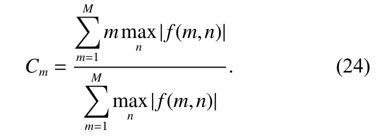
Using the center coordinates of the target in the image,the echoes are translated in the Doppler domain to make the target center in the Doppler center. By translating the target as a whole, the Doppler frequency of the main body symmetrical in the low frequency region, and then the CEMD algorithm is used as the m-D separation imaging. The translation process is expressed as

where p(n,m) is the range profile and k=0,1,···,M −1.This is the basic flow of the improved CEMD algorithm.
5. Experiment and performance analysis
5.1 Experiment on the simulated data
In this section, the performances of the CEMD algorithm and the proposed method are compared by using simulated data. The scatterer model of simulated data is shown in Fig.7. There are six scatterers in the model, where the scatterers 1-5 are from the rigid body, scatterers 1-4 are around the center 5 located at (2.5 m,0) with a radius of 2.5 m, and the scatterer 6 represents the rotating part rotating around (0, 0) at a speed of 6.67 Hz with a radius of 0.25 m. The reflection coefficient of scatterer 6 is twice that of others. The main body rotates about 1.84° over 512 pulses during the imaging time. The PRF is 2 KHz.The LFM signal is transmitted with the center frequency of 10 GHz, the pulse width is 25.6 μs and the bandwidth is 300 MHz. One hundred and twenty eight range cells per pulse are sampled.
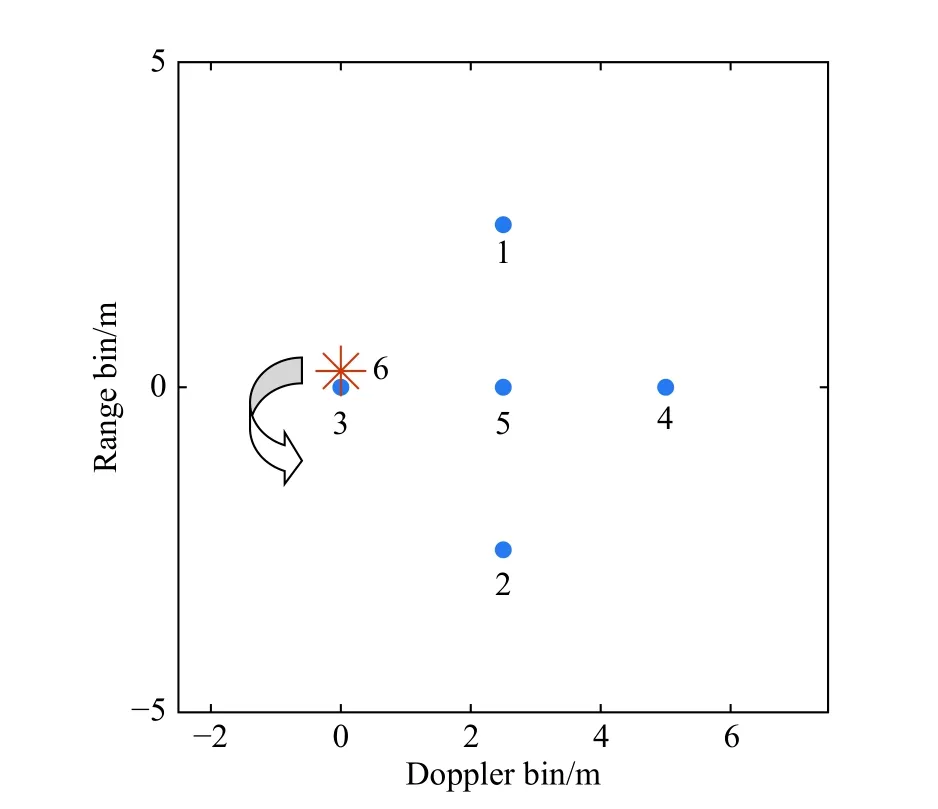
Fig. 7 Simulated model of micro-motion target
The received signal is generated by the above signal model. The noise is considered as additive and white Gaussian noise, and experiments are carried out at the signal-to-noise ratio (SNR) of 10 dB. Fig. 8(a) shows the ISAR image of the target without the micro-motion part by directly applying the R-D algorithm, and Fig. 8(b)shows the ISAR image of the target with the micro-motion part by directly applying the R-D algorithm. As shown in Fig. 8, the m-D signal generated by the scatterer 6 has a wide Doppler bandwidth, causing the scatterers 3-5 to be shadowed. The results of the m-D signal separation using the CEMD algorithm and the improved CEMD algorithm are shown in Fig. 8(c) and Fig. 8(d), respectively. Specifically, CEMD is performed on the range cells containing the rotating part. The signals of range cell 63,64, 65 are decomposed into 6, 7, 7 IMFs, respectively.Select 20 as the threshold of the zero-crossings number to distinguish the main body signal and the m-D signal.
However, since the target is not at the Doppler center in the simulation, the m-D signal is not completely removed and the image of the main body is destroyed, as marked by the arrow. The improved CEMD algorithm avoids these problems through the image is translated by six Doppler cells before CEMD, and obtains a well-focused image of the main body without inference. After the improved CEMD, the m-D interference is obviously removed and the main body is well preserved.
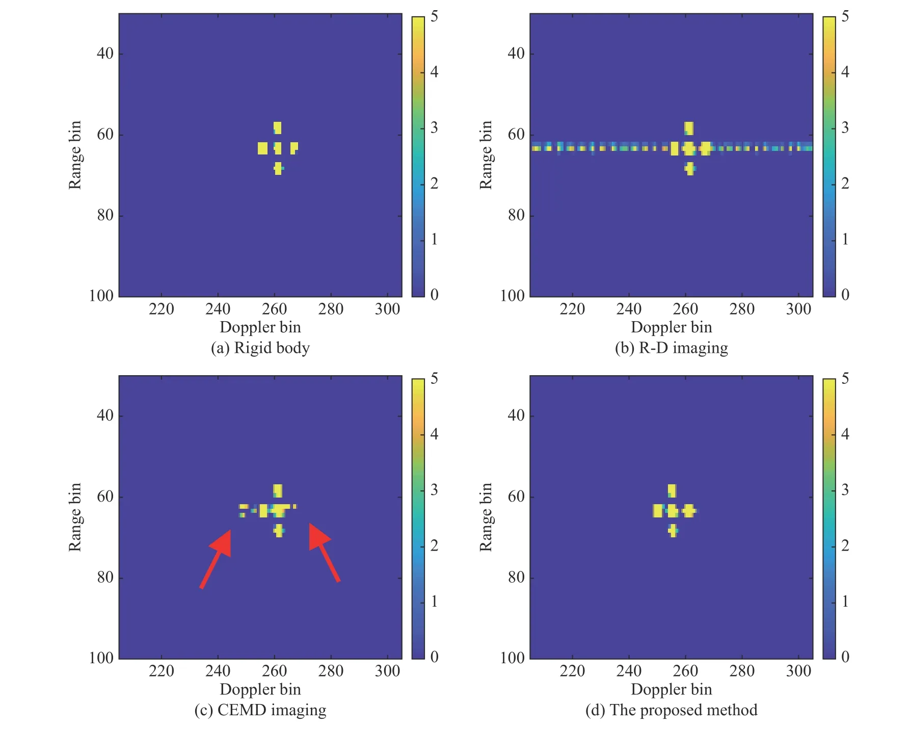
Fig. 8 Imaging results of the target without micro-motion parts based on the R-D algorithm and the imaging results of the target with micromotion parts
It should be noted here that the above-mentioned target center estimation is performed by using the rigid body image. In fact, the m-D signal will interfere with the estimation of the target center. Despite the interference, the proposed method can also improve the m-D removal effect to a certain extent.
5.2 Experiment on the raw data
In this section, the CEMD algorithm and the improved CEMD algorithm are applied to raw data of the propeller aircraft AN-26. The framework of the AN-26 is shown in Fig. 9(a).
After pulse compression and motion compensation, the target can be viewed as a turntable model. Fig. 9(b) shows the ISAR image of AN-26 directly by applying the R-D algorithm. The propeller of the aircraft introduces the m-D signal. The m-D signal is broadened in the Doppler domain, causing the main body to be shadowed.
The result of the CEMD algorithm is shown in Fig. 9(c).Specifically, performing CEMD on the range cells 132-145, which contains the m-D signal through observing,low frequency IMFs with zero-crossing less than 40 are selected to reconstruct the signal, and the main body can be imaged by the R-D algorithm. The number of zerocrossings in this experiment is obtained through trial.
The improper selection of the zero-crossings threshold will result in loss of the main body or incomplete separation of the m-D signal. The effect of m-D separation depends on the determination of the threshold. As can be seen from the result, in addition to the head and wing of the aircraft at the arrow, the m-D signal achieves better removal. Before, the cause of this problem is analyzed. In Fig. 9(c), the grid can roughly show the distribution of the target in the Doppler domain. The 320 scale is the Doppler center and the target clearly deviates from the center position. Since the m-D signal near the head of the target is in the low frequency region, the m-D interference is not completely removed. Instead, because the wing of the target is in the high frequency region, the signal of the main body is weakened.
The result of the improved CEMD algorithm is shown in Fig. 9(d). The center of the target in the image estimated by the above method is on the scale of 316.2. The grid in Fig. 9(d) is the same as in Fig. 9(c). It can be found that after the translation, the target in the image is approximately symmetrically distributed in the Doppler center, proving the correctness of the estimation method of the target center. The m-D signal can be removed more thoroughly and correctly by the improved CEMD algorithm. For example, at the arrow, the m-D interference near the head of the target is suppressed better, and the wing of the target is better preserved. Here, we have to say that the traditional accumulation correlation algorithm is used for the range alignment, and with the purpose to illustrate the superiority of the improved CEMD algorithm.
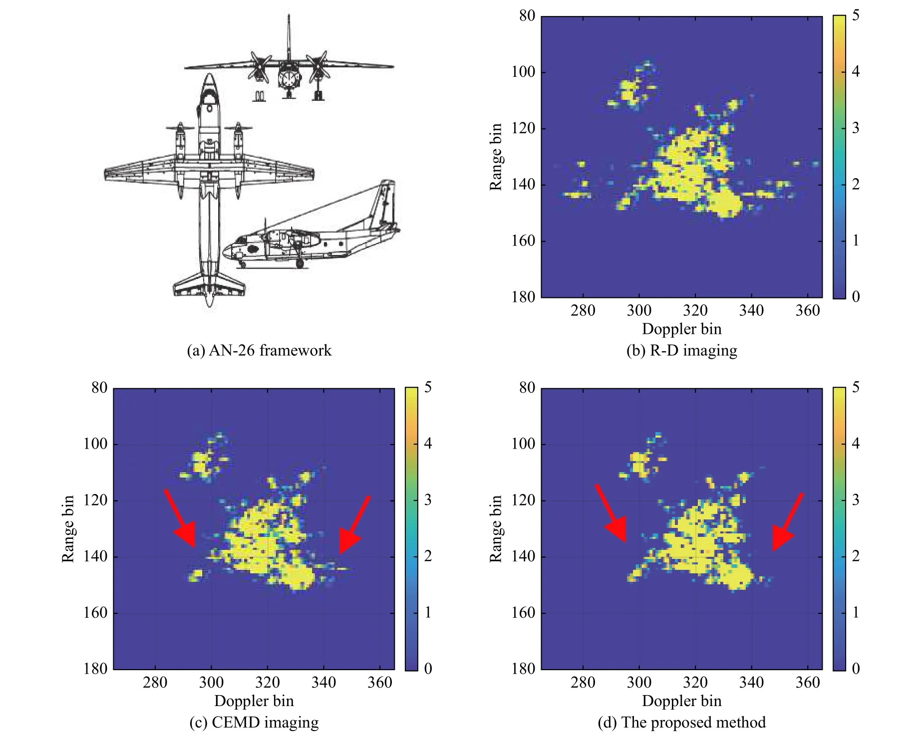
Fig. 9 Framework of AN-26 and the imaging results
The effectiveness of the new range alignment method proposed in this paper can also be verified combined with the improved CEMD algorithm. The results of the accumulation correlation algorithm, the global minimum entropy and preprocessing global range alignment algorithm are compared in Fig. 10. The entropies of the ISAR images are shown in Table 2. The proposed method achieves better focusing and the m-D signal is suppressed more thoroughly.

Fig. 10 Imaging results of raw data

Table 2 Entropies of ISAR images in Fig. 9
6. Conclusions
In this paper, we propose a novel preprocessing global range alignment algorithm for the micro-motion target and improve the CEMD algorithm. The range alignment algorithm combines the global method and the preprocessing method. The preprocessing process changes the optimization of the global method, which is considered to be more reasonable, and reduces the jump errors to improve the accuracy of range alignment and the quality of the ISAR image to some extent. By estimating the center of the target in image and translation, the improved CEMD algorithm overcomes the shortcomings of the CEMD algorithm, making m-D signal separation more thorough and the main body better retention. The experimental results for the simulated and raw data verify the effectiveness of the proposed algorithms.
 Journal of Systems Engineering and Electronics2021年1期
- Journal of Systems Engineering and Electronics的其它文章
- Unsplit-field higher-order nearly PML for arbitrary media in EM simulation
- A deep learning-based binocular perception system
- STAP method based on atomic norm minimization with array amplitude-phase error calibration
- Higher order implicit CNDG-PML algorithm for left-handed materials
- Fast and accurate covariance matrix reconstruction for adaptive beamforming using Gauss-Legendre quadrature
- Multiple interferences suppression with space-polarization null-decoupling for polarimetric array
