基于彩色编码相移条纹的相机标定
魏泊岩,田庆国*,葛宝臻
基于彩色编码相移条纹的相机标定
魏泊岩1,2,田庆国1,2*,葛宝臻1,2
1天津大学精密仪器与光电子工程学院,天津 300072;2光电信息技术教育部重点实验室,天津 300072
针对传统标定方法对靶标特征点模糊噪声适应性低的问题,提出一种基于彩色编码相移条纹的标定方法。以液晶显示面板为标定靶,依次显示水平和垂直彩色编码相移条纹;通过颜色通道分离,得到正交相移条纹;结合相移理论,以正交相位截断线的交点为特征点;多次改变靶标位姿,提取特征点,结合基于平面二维靶标的标定理论,实现单相机与双目立体视觉系统的标定。此外,在靶标图样四角添加彩色编码相移圆环,实现特征点的自动提取与排序,提高标定效率。实验结果表明,在拍摄靶标图像模糊时,单相机标定的重投影误差为0.15 pixels,标定后双目系统的测量标准偏差为0.1 mm。
相机标定;相位靶标;相移理论;三维测量
1 引 言
相机标定是视觉测量的关键步骤,标定精度直接影响视觉测量系统的精度,因此相机标定是视觉测量领域的研究热点[1]。基于平面二维靶标的标定方法操作简便,应用广泛[2],此方法使用待标定相机拍摄不同位姿的平面靶标,提取靶标特征点的图像坐标,通过特征点世界坐标与图像坐标的映射关系建立方程,求解相机的内外参数。精确提取特征点的图像坐标是通过此方法得到高精度标定结果的前提,常见特征点有圆域的中心[3]与棋盘格角点[4]。但受环境因素和相机对焦误差的影响,拍摄的靶标图像会出现不同程度的模糊[5],影响特征点的提取精度。而相位信息不受拍摄图像模糊的影响[6],有学者提出使用显示相位图样的液晶显示面板作为标定靶[7-10],通过相位编码建立特征点世界坐标与图像坐标的对应关系,实现相机的高精度标定。
刘元坤等[7]提出以正交正弦条纹作为靶标图样,通过傅里叶分析法计算正交包裹相位分布,建立特征点图像坐标与世界坐标的联系,实现相机标定;李璐璐等[8]针对使用傅里叶分析法处理正交正弦条纹提取边缘特征点误差较大的缺陷,采用四步相移法提取相位,以正交正弦相移条纹作为靶标图样,提高标定精度;此方法在每个靶标位姿下,需要采集8幅图像。Ma等[9]使用水平和垂直三步相移条纹图作为靶标图样,分别提供水平和垂直方向的相位约束,对特征点进行相位编码;此方法标定精度高,稳健性好,在每个靶标位姿下,需要采集6幅图像。杨浩等[10]通过向平面圆靶标投射正交正弦相移条纹,对平面圆靶标特征点进行相位编码,实现采集图像模糊时相机的高精度标定,此方法在每个靶标位姿下,需要采集12幅图像。相比基于傅里叶分析法的标定方法,基于相移理论的标定方法精度较高,但在每个靶标位姿下需采集多幅图像,标定流程繁琐。此外,上述标定方法在提取特征点时,需要人为干预,即手动点选四个外角点,来确定特征点提取的目标区域,标定过程复杂,在此提出特征点自动提取与排序算法,简化标定流程。
为了克服相移条纹标定方法采集图像数目多、过程复杂等问题,考虑彩色相位编码条纹同时包含彩色信息和相位信息的优势[11-12],本文提出基于彩色编码相移条纹的标定方法。本方法通过彩色图案的RGB通道编码相移条纹,减少采集图像的数目;在靶标图案四角添加彩色编码相移圆环,实现特征点自动检测与排序。实验结果表明,采集图像模糊时,仍可实现特征点自动检测与排序,标定精度高;图像模糊程度增加,标定结果保持稳定;相同靶标位姿变换次数下,本文方法所需采集图像数目为基于正交正弦相移条纹标定方法的三分之一,且标定精度相当;采集图像数目相同时,本文方法的标定精度高于基于正交正弦相移条纹的标定方法。
2 基本原理
2.1 基于平面二维靶标的标定方法
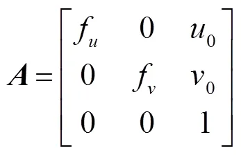
对于基于平面二维靶标的标定方法,设相机模型为针孔模型[13],世界坐标系建立在平面二维靶标上,则所有特征点的坐标为0,特征点的图像坐标与世界坐标的对应关系为

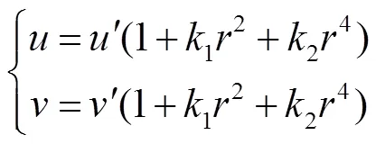
根据基于二维平面靶标标定方法[15]:使用待标定相机拍摄不同位姿的标定靶,同时提取特征点的图像坐标,利用特征点图像坐标与世界坐标对应关系,线性求解相机的内外参数;结合畸变模型,通过迭代法或多项式近似法[16]求解畸变系数,实现单相机的标定。
2.2 靶标图案的生成
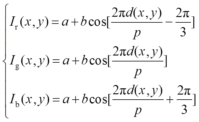
靶标包含两幅彩色图像:垂直和水平彩色编码相移条纹图,其RGB通道的强度分布表示如下:

2.3 特征点的提取与排序
在每个靶标位置,液晶显示面板依次显示垂直和水平彩色编码相移条纹图,拍摄得到的垂直和水平彩色编码相移条纹如图2所示,其中2(a)为垂直彩色编码相移条纹图,2(b)为水平彩色编码相移条纹图。

图1 基于彩色编码相移条纹的相位靶标。(a) 垂直彩色编码相移条纹图;(b) 水平彩色编码相移条纹图
特征点的提取与排序步骤如下:


2) 用1,2,3表示调制处理后图像中三个颜色通道的灰度分布。结合相移理论[19],可通过式(7)得到垂直和水平包裹相位图。

3) 由于相位调制区域与背景存在灰度差异,通过式(8)分离相位调制区域[20]

其中阈值T为0.2时效果好,可在保留相位信息的前提下,最大程度地去除背景噪声。在此基础上,通过腐蚀膨胀[21]操作,去除包裹相位图中的离散噪声点以及孔洞。图3为最终得到的包裹相位图,其中3(a)为垂直包裹相位图,3(b)为水平包裹相位图。

图3 去除背景后的效果。(a) 垂直包裹相位图;(b) 水平包裹相位图
4) 对垂直和水平包裹相位图进行边缘检测[22],将边缘检测的结果直接叠加,保存两张图中边缘交点坐标。此时边缘交点为特征点和彩色编码相移圆环引入的交点,对包裹相位图椭圆检测[23],提取定位点坐标,通过判断边缘交点与定位点的距离即可去除彩色编码相移圆环引入的交点,仅保留标定所需特征点,如图4(a)所示。
5) 特征点的排序:① 首先对四个定位点进行排序:选定一个定位点,作为定位点1,通过判断特征点是否在定位点1与其余定位点连线同侧确定对角定位点,将定位点1的对角定位点作为定位点3,其余两个定位点分别为定位点2和定位点4,如图4(b)所示。② 二维平面的射影变换可用式(9)表示:

3 标定步骤
3.1 相机标定步骤
相机标定步骤为:1) 使用液晶显示面板作为标定靶,改变(³3)次标定靶的位姿,在每个靶标位姿下,依次显示垂直和水平彩色编码相移条纹图,相机共计拍摄2张图片;2) 对于每个位姿下拍摄的垂直和水平彩色编码相移条纹图进行颜色通道分离,结合相移理论得到水平和垂直包裹相位图;3) 提取水平和垂直包裹相位图相位截断线,进行叠加,得到交点像素坐标;4) 通过定位点对特征点进行排序;5) 使用基于平面二维靶标的标定方法[15]实现相机标定。
3.2 相机标定结果的优化
为了进一步提高标定精度,需对标定得到各参数进行非线性优化,使得重投影误差最小,目标函数定义为

4 实验结果与分析
4.1 单相机标定实验
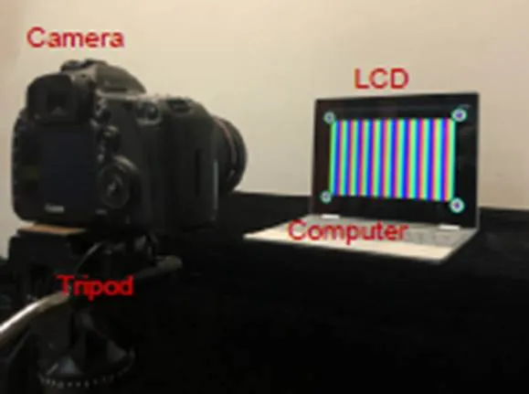
单相机标定实验系统如图5所示,待标定相机CCD分辨率为5760 pixels´3840 pixels,镜头焦距为105 mm,液晶显示面板的分辨率为3000 pixels´2000 pixels,尺寸为12.3 inch(1 inch=2.54 cm),像素间距为0.087 mm。
相机对焦于1.5 m处,此时前景深为22.4 mm(允许弥散圆半径为0.03 mm),使用基于平面二维靶标的标定方法[15]进行标定,在成像距离1.3 m附近改变15次靶标位姿,分别使用棋盘格靶标标定方法、文献[7]提出的基于正交正弦条纹的标定方法、文献[9]提出的基于正交正弦相移条纹的方法以及本文方法进行标定实验,标定靶标图案均通过液晶显示面板显示,其中靶标相邻角点间距为28.7 mm。
相机内参数标定结果、重投影误差如表1所示,畸变系数、标定采集的图像数如表2所示。

图4 特征点提取与排序。(a) 特征点提取结果;(b) 定位点排序;(c) 排序后的特征点

图5 实验装置图
从标定的结果可以看出,在靶标离焦时,靶标位姿变换次数相同的前提下,棋盘格靶标标定的重投影误差最大,为0.53 pixels;三种相位靶标的标定重投影误差均在0.21 pixels以下;其中文献[7]提出的基于正交正弦条纹靶标在三种相位靶标中,标定精度最低,重投影误差为0.21 pixels;本文相位靶标标定重投影误差为0.15 pixels,标定精度略低于文献[9]提出的基于正交正弦相移条纹靶标,但标定所需采集图像数目为正交正弦相移条纹靶标的三分之一,简化了标定步骤。
在此基础上,在采集图像数目相同的前提下进行标定实验,当采集图像总数为30时,棋盘格靶标标定方法可以改变30次靶标位姿,文献[7]的方法可以改变30次位姿,文献[9]的方法可以改变5次位姿,本文方法可以改变15次位姿,相机的参数与液晶显示面板参数与上述实验一致,标定得到的内参数、畸变系数以及重投影误差如表3所示。
当采集图像数目相等的前提下,比较各种方法的重投影误差,本文方法的误差最小,为0.12 pixels;棋盘格标定方法的误差为0.47 pixel;文献[7]方法的误差为0.26 pixels;文献[9]方法的误差最大,为0.53 pixels。
为了进一步验证所提标定方法在图像模糊时的鲁棒性,其他实验参数不变,通过改变靶标的成像距离,改变离焦程度,得到不同模糊程度的图像。相机对焦于1.5 m处,成像距离分别为1.4 m,1.0 m,0.6 m,在每个标定位置均改变15次标定靶的位姿。由于改变成像距离会改变靶标在相机视野中的占比,为了保证靶标在相机视野中的占比一致,需要改变彩色编码相移条纹的周期,不同标定距离下,条纹周期分别为:(1.4 m, 250 pixels),(1.0 m, 180 pixels),(0.6 m, 100 pixels)。

表1 内参数标定结果

表2 畸变系数与采集图像数目

表3 标定结果
标定过程中拍摄的部分靶标图像与对应特征点提取结果如图6所示,其中6(a)~6(c)为距离1.4 m拍摄与提取的结果,6(d)~6(f)为距离1.0 m拍摄与提取的结果,6(g)~6(i)为距离0.6 m拍摄与提取的结果。
从图6中可以看出,随着靶标离焦距离增加,拍摄的图像模糊程度增加,但是仍然可以稳定提取特征点,不同成像距离下内参数、畸变系数与重投影误差如表4所示。
从重投影误差可以看出,随着待标定相机与标定靶距离减小,图像的离焦程度增大,标定重投影误差较为稳定,最大不超过0.21 pixels,此实验说明在离焦情况下,所提标定方法鲁棒性良好。
4.2 双目立体视觉系统标定及重建实验
为了进一步验证所提标定方法的有效性,在单相机标定的基础上,进行双目立体视觉系统标定和模型重建实验。使用双目系统拍摄同一标定靶,在标定两相机内外参数与畸变系数的基础上,可得到两相机坐标系之间的旋转矩阵和平移向量以及系统结构参数。设世界坐标系与双目系统左相机坐标系重合,使用标定后的双目系统拍摄待测物,根据系统的内外参数对拍摄得到的图像进行立体校正[24],并对校正后的图像进行立体匹配[25],得到视差图,通过左相机图像的像素坐标及其对应视差,就可得到对应点的三维坐标[26],实现待测物的三维重建。
实验系统如图7所示,两相机除焦距为70 mm外,其余参数与4.1中一致,两相机均对焦于1.5 m处,在标定靶成像距离1.3 m,改变15次标定靶位姿,对双目立体视觉系统进行标定。双目系统两相机内参数与畸变系数如表5所示,系统结构参数如表6所示。
使用标定后的双目系统在对焦位置拍摄角点间距为30 mm的金属棋盘格靶标,对相邻角点间距进行测量。左右相机采集的图像如图8(a)、8(b)所示,对棋盘格的角点进行三维重建,重建效果如图8(c)所示,水平相邻角点的平均距离为30.14 mm,垂直相邻角点的平均距离为30.04 mm,所有相邻角点平均距离为30.12 mm,标准差0.1 mm,说明标定方法有效。
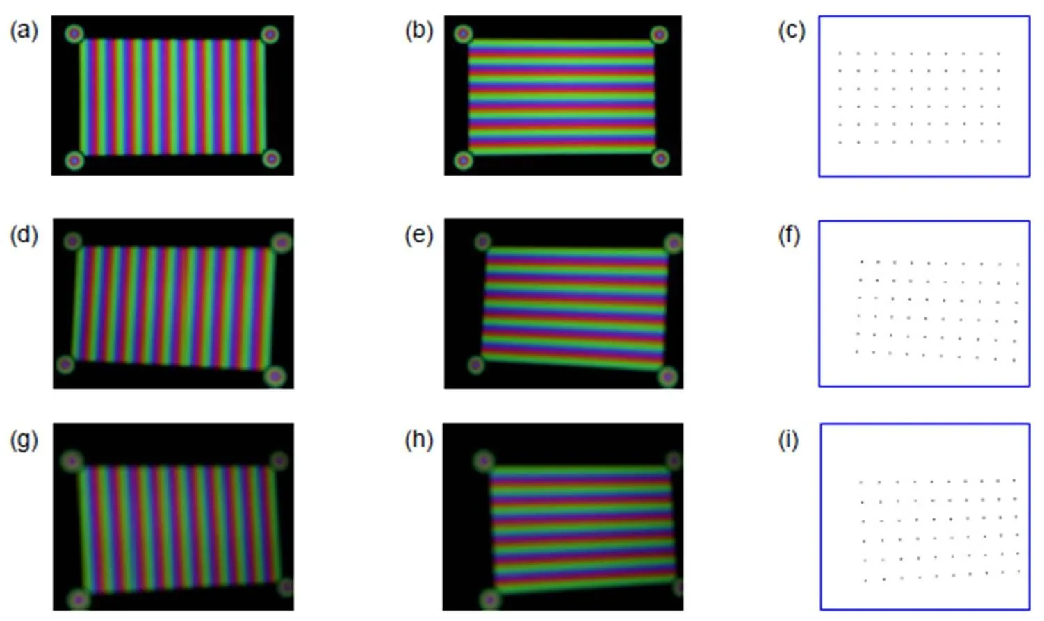
图6 不同距离下拍摄的靶标以及对应特征点提取结果。 (a)~(c) 距离1.4 m拍摄与提取的结果;(d)~(f) 距离1.0 m拍摄与提取的结果;(g)~(i) 距离0.6 m拍摄与提取的结果

表4 标定内参数及重投影误差
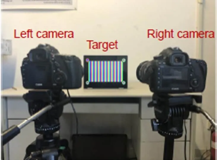
图7 实验装置图
在此基础上,使用标定后的双目系统在对焦位置拍摄石膏人像,由于被动双目立体视觉方法对表面特征不明显的物体难以获取足够的三维信息[27],因此对石膏人像进行着色,增加被测物特征点,提高立体匹配的精度。左右相机采集的图像如图9(a)、9(b)所示,得到的三维点云图如图10所示,其中10(a)为主视图,10(b)为左视图,10(c)为右视图,点云还原了被测石膏人像的形貌,验证了标定方法的有效性,可以应用于双目立体视觉的三维重建系统。

表5 双目相机内参数以及重投影误差

表6 双目系统的结构参量

图8 双目立体视觉系统的左右视目图及棋盘格角点的三维重建。(a) 左相机拍摄的标定靶;(b) 右相机拍摄的标定靶;(c) 棋盘格角点的三维重建

图9 双目立体视觉系统的左右视目图。(a) 左相机拍摄的石膏人像;(b) 右相机拍摄的石膏人像

图10 石膏人像的三维点云图。(a) 主视图;(b) 左视图;(c) 右视图
5 结 论
本文介绍了通过液晶显示面板分别显示水平和垂直方向的彩色编码相移条纹来进行相机标定的方法。此方法通过颜色通道编码相移条纹,减少标定所需采集图像数目;通过在靶标图案四角添加彩色编码相移圆环,实现特征点的自动排序,简化标定流程。单相机标定实验表明,采集靶标图案模糊时,在标定靶位姿改变次数相同的前提下,本文方法的标定精度明显优于棋盘格靶标,也高于正交正弦条纹靶标,虽略低于正交正弦相移条纹靶标,但采集图像的数目仅为正交正弦相移条纹靶标的三分之一;采集图像总数相同时,此标定方法的重投影误差最小,精度最高;不同离焦程度下,标定精度稳定。双目系统标定实验表明,标定后系统的测量精度高,可实现被测物的三维重建。
[1] Li L L, Zhao W C, Wu F,. Experimental analysis and improvement on camera calibration pattern[J]., 2014, 53(1): 013104.
[2] Mallon J, Whelan P F. Which pattern? Biasing aspects of planar calibration patterns and detection methods[J]., 2007, 28(8): 921–930.
[3] Li D, Tian J D. An accurate calibration method for a camera with telecentric lenses[J]., 2013, 51(5): 538–541.
[4] Liu Z, Wu Q, Chen X,. High-accuracy calibration of low-cost camera using image disturbance factor[J]., 2016, 24(21): 24321–24336.
[5] Bell T, Xu J, Zhang S. Method for out-of-focus camera calibration[J]., 2016, 55(9): 2346–2352.
[6] Wang Y W, Chen X C, Tao J Y,. Accurate feature detection for out-of-focus camera calibration[J]., 2016, 55(28): 7964–7971.
[7] Liu Y K, Su X Y. A new camera calibration technique using FTP method[J].(), 2007, 39(6): 149–153. 刘元坤, 苏显渝. 基于傅里叶条纹分析的摄像机标定[J]. 四川大学学报(工程科学版), 2007, 39(6): 149–153.
[8] Li L L, Zhao W C, Wu F,. Analysis and improvement of characteristic points extraction algorithms in camera calibration[J]., 2014, 34(5): 0515002. 李璐璐, 赵文川, 伍凡, 等. 摄像机标定中的特征点提取算法研究与改进[J]. 光学学报, 2014, 34(5): 0515002.
[9] Ma M C, Chen X C, Wang K Y. Camera calibration by using fringe patterns and 2D phase-difference pulse detection[J]., 2014, 125(2): 671–674.
[10] Yang H, Cai N, Lin B,. Defocus camera calibration based on sinusoidal phase coding[J]., 2018, 47(7): 0715002. 杨浩, 蔡宁, 林斌, 等. 基于正弦相位编码的相机离焦标定[J]. 光子学报, 2018, 47(7): 0715002.
[11] Ge W. Research on 3D measurement based on color phase-encoded fringe projection[D]. Nanjing: Dongnan University, 2016: 4–6.
葛尉. 基于彩色相位编码条纹投影的三维测量方法研究[D]. 南京: 东南大学, 2016: 4–6.
[12] Pan J H, Huang P S, Chiang F P. Color phase-shifting technique for three-dimensional shape measurement[J].2006, 45(1): 013602.
[13] Heikkila J. Geometric camera calibration using circular control points[J]., 2000, 22(10): 1066–1077.
[14] Huo J, Yang W, Yang M. A self-calibration technique based on the geometry property of the vanish point[J]., 2010, 30(2): 465–472. 霍炬, 杨卫, 杨明. 基于消隐点几何特性的摄像机自标定方法[J]. 光学学报, 2010, 30(2): 465–472.
[15] Zhang Z Y. Flexible camera calibration by viewing a plane from unknown orientations[C]//1999, 1: 666–673.
[16] Zhang Z H. Review of single-shot 3D shape measurement by phase calculation-based fringe projection techniques[J]., 2012, 50(8): 1097–1106.
[17] Wang N, Zhang Q C, Ma K. 3-D shape measurement for isolated objects based on color-encoded fringe projection[J]., 2010, 21(8): 1227–1231.王娜, 张启灿, 麻珂. 基于彩色编码条纹投影的孤立物体三维测量[J]. 光电子·激光, 2010, 21(8): 1227–1231.
[18] Liu D H, Lin B. Fourier transform profilometry using zero frequency elimination based on gray modulation[J]., 2011, 40(11): 1697–1701. 刘大海, 林斌. 利用强度调制消除零频的傅里叶变换轮廓测量[J]. 光子学报, 2011, 40(11): 1697–1701.
[19] Huang P S, Zhang S. Fast three-step phase-shifting algorithm[J]., 2006, 45(21): 5086–5091.
[20] Lu J, Mo R, Sun H B,. Invalid phase values removal method for absolute phase recovery[J]., 2016, 55(2): 387–394.
[21] Nellros F, Thurley M J, Jonsson H,. Automated measurement of sintering degree in optical microscopy through image analysis of particle joins[J]., 2015, 48(11): 3451–3465.
[22] Chen N Q, Wang J J, Yu L A,. Sub-pixel edge detection of led probes based on canny edge detection and iterative curve fitting[C]//,,2014, 6: 131–134.
[23] Yuen H K, Princen J, Illingworth J,. Comparative study of Hough transform methods for circle finding[J]., 1990, 8(1): 71–77.
[24] Tsai R Y. A versatile camera calibration technique for high-accuracy 3D machine vision metrology using off-the-shelf TV cameras and lenses[J]., 1987, 3(4): 323–344.
[25] Kaehler A, Bradski G.[M]. Beijing: O'Reilly Media, Inc., 2016.
[26] Wang S, Xu X. 3D reconstruction based on horopter[J]., 2017, 37(5): 0515004. 王珊, 徐晓. 基于双目单视面的三维重建[J]. 光学学报, 2017, 37(5): 0515004.
[27] Sun J H, Yang Y, Zhang G J. Three dimensional scanning technique using color structured light patterns based on phase moving coding strategy[J]., 2008, 34(1): 122–125. 孙军华, 杨扬, 张广军. 基于相移的彩色结构光编码三维扫描技术[J]. 光学技术, 2008, 34(1): 122–125.
Camera calibration based on color-coded phase-shifted fringe
Wei Boyan1,2, Tian Qingguo1,2*, Ge Baozhen1,2
1School of Precision Instruments and Opto-Electronics Engineering, Tianjin University, Tianjin 300072, China;2Key Laboratory of Opto-Electronics Information and Technology, Ministry of Education, Tianjin 300072, China
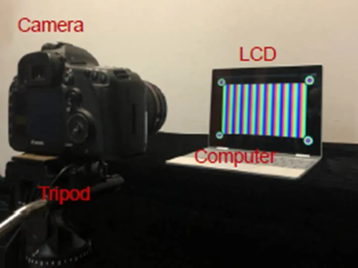
Calibration system
Overview:In the past two decades, camera calibration theory has been continuously developed and improved. The calibration method based on planar two-dimensional targets has been most widely applied. In the actual calibration process, the captured target images would appear to various degrees of blurring due to environmental factors and camera focus errors. The accuracy of feature point extraction would be affected. Since the phase information is not influenced by the blur of the captured image, some scholars have proposed using a liquid crystal display panel that displays phase patterns as a calibration target. The phase code is used to establish the correspondence between feature point world coordinates and image coordinates to achieve high-precision calibration of the camera. Compared with the calibration method based on Fourier analysis, the calibration method based on phase shift theory has higher accuracy. However, its calibration process is cumbersome because multiple images need to be collected for each target pose. Furthermore, such calibration methods require human intervention when extracting feature points, that is, manually selecting four outer corner points to determine a target area for feature point extraction. The calibration process is complicated.
This paper proposes a calibration method based on the color-coded phase-shifted fringe to overcome the shortcomings of the calibration method based on phase-shifted theory. This method encoded a phase-shifted stripe through the RGB channels of a color pattern and used a liquid crystal display panel as a calibration target to sequentially display horizontal and vertical color-coded phase-shifted stripes. Through the color channel separation, orthogonal phase-shifted fringes were obtained. The intersection point of the orthogonal phase truncation line was taken as the characteristic point according to the phase-shifted theory. Applied the calibration theory based on the planar two-dimensional target, the calibration of the single-camera and binocular system was realized by changing the target pose multiple times and extracting feature points. Furthermore, calibration efficiency was improved by adding color-coded phase-shifted rings to the four corners of the target pattern to automatically extract and sort feature points. The single-camera calibration experiment shows that when the target pattern is blurred, the calibration accuracy of the method in this paper is significantly better than that of the chessboard target under the premise that the calibration target pose changes the same number of times. It is slightly higher than the orthogonal sinusoidal fringe target and slightly lower than the orthogonal sinusoidal phase-shifted fringe target. The experiment also shows that the number of pictures collected by this method is only one-third of the orthogonal sinusoidal phase-shifted fringe target. When the total number of collected pictures is the same, the reprojection error of this calibration method is the smallest and the precision is the highest. The calibration accuracy is stable under different defocusing degrees. The binocular system calibration experiment shows that the system has high measurement accuracy after calibration, and it can realize 3D reconstruction of the measured object.
Wei B Y, Tian Q G, Ge B ZCamera calibration based on color-coded phase-shifted fringe[J]., 2021, 48(1): 200118; DOI:10.12086/oee.2021.200118
Camera calibration based on color-coded phase-shifted fringe
Wei Boyan1,2, Tian Qingguo1,2*, Ge Baozhen1,2
1School of Precision Instruments and Opto-Electronics Engineering, Tianjin University, Tianjin 300072, China;2Key Laboratory of Opto-Electronics Information and Technology, Ministry of Education, Tianjin 300072, China
Aiming at the low adaptability of blurring noise of target feature points in traditional calibration methods, a calibration method based on the color-coded phase-shifted fringe is proposed. Using a liquid crystal display panel as the calibration target, horizontal and vertical color-coded phase-shifted stripes are displayed in sequence; the orthogonal phase-shifted stripes are obtained by separating color channels; based on the phase-shifteg theory, the intersections of the orthogonal phase truncation lines are calculated as the feature points. After changing the target position multiple times and extracting feature points, the plane-based camera calibration technique is applied to realize the calibration of both the single camera and the binocular system. Furthermore, color-coded phase-shift circles are added to four corners of the target pattern to automatically extract and sort feature points. Accordingly, the efficiency of calibration is promoted. The experimental results indicate that when the target image is blurred, the reprojection error of the single-camera calibration is 0.15 pixels, and the standard deviation of the binocular system measurement after calibration is 0.1 mm.
camera calibration; phase target; phase-shift theory; 3D measurement
TP391;TB852.1
A
10.12086/oee.2021.200118
National Natural Science Foundation of China (61535008)
* E-mail: tianqingguo@tju.edu.cn
魏泊岩,田庆国,葛宝臻. 基于彩色编码相移条纹的相机标定[J]. 光电工程,2021,48(1): 200118
Wei B Y, Tian Q G, Ge B ZCamera calibration based on color-coded phase-shifted fringe[J]., 2021, 48(1): 200118
2020-04-10;
2020-06-15
国家自然科学基金资助项目(61535008)
魏泊岩(1994-),男,硕士研究生,主要从事计算机视觉的研究。E-mail:weiboyan@tju.edu.cn
田庆国(1973-),男,博士,副教授,主要从事计算机可视化、图像图形学的研究。E-mail:tianqingguo@tju.edu.cn

