Study on the voltage and temperature monitoring system for electrolytic cell based on ARM
Li-yuan YANG,Ying ZHAO*,Yan-juan LI
(1 Electrical&Information Engineering College,Beihua University.Jilin 132021,China)
(2 College of Information and Computer Engineering,Northeast Forestry University,Harbin 150040,China)
Abstract:Aiming at the problems existing in the voltage and temperature of electrolytic cell of wet electrolytic copper,combining the development trend and successful experiences of domestic electrolytic industry,an automatic monitoring system for the circuit detection of voltage and temperature of electrolytic cell in the process of electrolytic copperwas developed.The system is composed of64 unit cellmonitoring devices and 2 gateways.The unit cellmonitoring device processes the collected voltage and temperature data through the ARM processor,and then transmits them to the host for real-time processing and display through the RS-485 bus.For the strong electromagnetic interference environment,the system adopts DC/DC power isolation,digital filtering,TVS and selfrecovery insurance technology,which can effectively inhibit the surge interference and improve the security and stability of the system operations.
Key words:ARM microprocessor,Electrolytic cell,DC/DC power supply isolation
1 Introduction
The production method of separating copper,nickel,zinc,lead,chromium and cobalt outby electrolytic cell iswidely used in metallurgical industry.However,because the environment of production methods is environment with strong corrosive,strong magnetic field,strong current,the on-line monitoring of electrolyzer cell voltage and electrode voltage between cathode and anode is difficult.The artificial patrol,touching,sprinklermethods are used to judge as short circuit,cold plate.As a result,production quality control is difficult,unit power consumption is increased,and labor intensity of field operation is high.The actual production energy consumption is generally higher than energy consumption of design.In order to make the electrolytic cell work stably,effectively and safely,the monitoring of the voltage and temperature of the electrolytic cell becomes a very important link.The key problem of themonitoring system is to eliminate the interference of the complex industrial field environment for the signal acquisition,and ensure the stability of the system.Therefore,the system technologists can adjust the process parameters in time according to the voltage and temperature,find the fault,shorten the fault time,prolong the service life of the equipment and improve the efficiency.
2 Overall schem e design of the system
The electrolytic cell voltage and temperature monitoring system designed in this paper(calculated according to 512 electrolytic cells)is composed of64 unit cellmonitoring devices and 2 gateways,each monitoring devicemonitors the voltage and temperature of 8 electrolytic cells,and each gateway connects32monitoring devices.
The unit cell monitoring device includes the cell voltage signal acquisition module[1],the electrolytic cell temperature signal acquisition module,the isolated power supplymodule,the ARM processingmodule and the data communication module.After receiving the acquisition instruction,voltage and temperature signals are sampled,and the data are processed by the processor and transmitted to the host via RS-485 bus for real-time display and storage.The process personnel can further analyze the status of the electrolytic cell according to the fluctuation of the collected electrolytic cell voltage and temperature parameters,and make corresponding treatment measures to ensure safe,stable and reliable operation of the electrolytic production process[2].The system structure is shown in Fig.1.
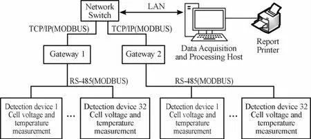
Fig.1 System structure diagram
3 Hardw are circuit design ofm onitoring system
The hardware circuit of the electrolytic cell voltage and temperaturemonitoring device designed in this paper is composed of five parts,including the voltage signal acquisition module,the temperature signal acquisition module,the isolated power supply module,the ARM processingmodule and the data communication module.The control core of themonitoring device adopts 32-bit ARM processor STM32F103VET6,with CortexM3 core,72 MHzmain frequency,64K SRAM and a variety of peripherals,which can meet the design requirements of the system.
The voltage signal acquisition module adopts AD7606[3]high-speed ADC converter and hardware overvoltage and overcurrent protection circuit.The AD7606 has high rate,high resolution and oversampling function,which can provide higher SNR performance.The hardware protection circuit adopts high-common-mode suppression,high-impedance differential input and TVS surge limiting device[4],which can effectively deal with the high-voltage problem caused by the voltage fluctuation in the cell and flashover,and improve the anti-interference ability of the acquisition circuit.The temperature acquisition module adopts the digital temperature sensor DS8B20,and realizes the temperature signal acquisition of 8-way electrolytic cell through the single-bus isolation technology.The application of isolation and limited slope long line driving technology greatly improves the anti-interference ability of single bus.The system adoptsmulti-DC/DC power source isolation technology to provide power to temperature module,voltage acquisition and processor module and communication module respectively,reduces effectively the impact of common mode voltage interference.The data communication module is responsible for sending the sampled data to the host through the network for display,alarm and storage.The hardware structure of the system is shown in Fig.2.
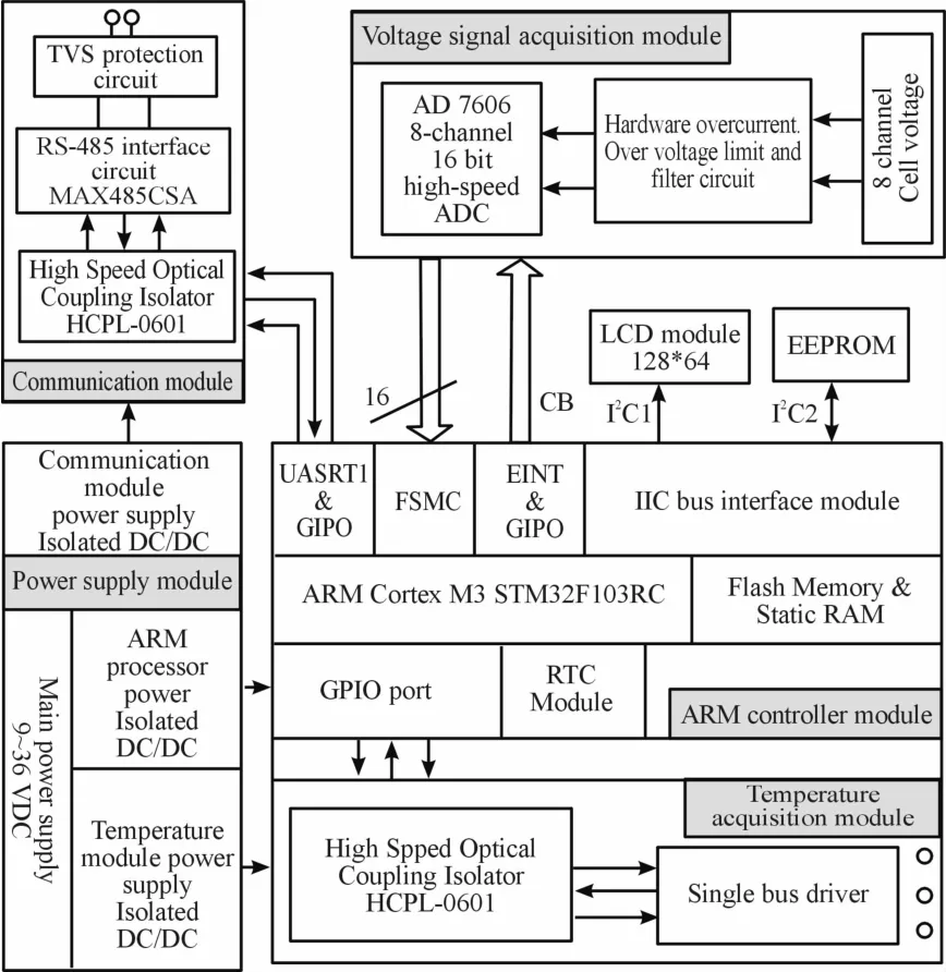
Fig.2 System hardware structure diagram
3.1 Voltage acquisition module of electrolytic cell
There are many interference factors in the field of industrial electrolytic copper production,the characteristics of strong current will produce strong electromagnetic interference,so the voltage signal acquisition channel requires a high capacity of commonmode suppression;Current mutation and abnormal state requires acquisition circuit has very strong protection function in order to avoid damage of high voltage differentialmode signal.High voltage common mode interference caused by fault should be considered when running multiple detection devices[5].The system adopts DC/DC power isolation and filter protection circuit composed of instrument amplifier and TVS device to avoid damage caused by high voltage differentialmode signal.The principle block diagram of voltage acquisition module is shown in Fig.3.
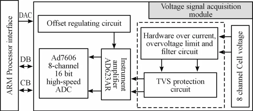
Fig.3 The p rincip Ieb Iock diagram of vo Itage acquisition modu Ie
The voltage signal conditioning and protection circuit is shown in Fig.4.Instrumentation amplifier U5(AD623AR)constitute a differential input and output gain control circuit,R33,R34,R35,R38,R39 and R40 constitute the signal partial voltage circuit in order to provide high-voltage and current-limiting protection,and realize the overvoltage inclusion function with D3 surge suppressor(TVS).In 5 V power supply,the common-mode input range up to 50 V,the maximum input voltage is 500 V,which is can effectively avoid the damage caused by voltage of the input increases.U5 instrument amplifier adopts double-terminal output mode,Vref provides bias voltage by DAC,and the output signal is transmitted to AD7606 differential input terminal,which can effectively reduce the common mode interference caused by strong magnetic field,and is conducive to PCB wiring design.When electrolytic copper is used,the electrolytic cell voltage is very low,around 0.4 V.Since U5 is supplied by a single power supply and the gain is set to 100,the normal output range is between 0.5 V and 4.5 V.The input protection circuit shall adopt 1%high-precision metal film resistance and be precisely matched to improve the common-mode suppression ability.
The ADC chip AD7606 with 16-bit synchronous sampling is adopted in the analog-digital conversion circuit,which has high speed,low power consumption and high resolution.It has 8-channel synchronous sampling input and 200KSPS sampling rate,ensuring the real-time performance of signal sampling.In the 5 V single power supplymode,the internal2.5 V reference is adopted and the ADC input range is set to±5.0 V.
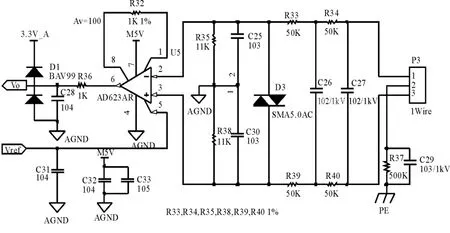
Fig.4 Vo Itagesigna I conditioning and protection circuit
3.2 Temperature acquisition module
Temperature affects the electrolytic power consumption and the structure of the cathode deposit and purity.As the temperature increases,the electrolyte viscosity decreases,the ion migration speed increases,and the conductivity increases.According to the determination,the conductivity of the electrolyte in 55℃is 2.5 times to that in 25℃.The rise of the conductivity will decrease the voltage,which will reduce the electrolysis,and the electrolyte temperature will go up,the electrolyte resistance will decrease,and the current of the salient point of the cathode will be reduced,and the formation of the irregular objects will be reduced,and the structure of the copper sedimentwill be improved.
But too high temperature will consume too much steam.It usually accelerates the evaporation of electrolytic cell liquid level,worsens the operating environment and aggravates the corrosion of plant and equipment.Therefore,detecting the change of cell temperature and controlling it in a reasonable scope can save energy and reduce consumption,improve the quality of production.Generally the electrolytic temperature is 60℃.
Function block diagram of temperature acquisition module is shown in Fig.4.It includes isolated power supply,photoelectric isolated communication,logic conversion and signal conditioning,limited-slope drive and output protection and other circuit units.Fig.5 is the functional block diagram of electrolytic cell temperature detectionmodule.The single-bus digital temperature sensor DS18B20 with armored probe is used to detect the temperature of 8-way electrolytic cell.The measuring temperature ranges from-55℃to+125℃,the precision is±0.5℃.These canmeet the requirements of electrolyzer temperaturemeasurement.
In order to reduce the influence of field strong electromagnetic field interference,the isolated single-bus limited-slope long line drive circuit is designed in the system to realize reliable transmission of TTL level within 200 meters.In Fig.5,Q3,R60,D12,C54,Q4,R67,D13 and C56 constitute the limited-slope driver,U14C and U14D constitute the logic conversion,and R61,R64,R65 and F1 constitute the output current-limiting and voltage-limiting protection circuit.The application of bus isolation and slope limiting technology improves the stability and reliability of the temperature detection circuit,and further improves the anti-interference ability and security of the system.
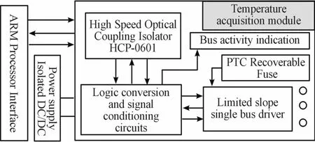
Fig.5 Function bIock diagram of tem perature acquisition modu Ie
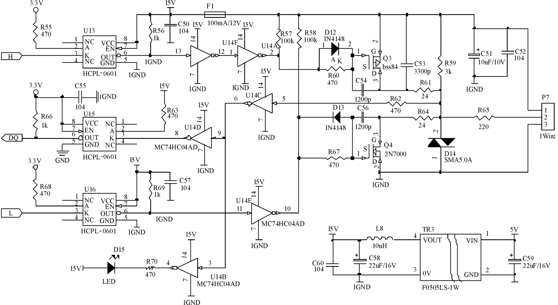
Fig.6 Schem atic diagram of tem perature acquisition m odu Ie
4 The softw are design of control system
4.1 Overall structure block diagram of the software
By analyzing the functional requirements of themonitoring device,the function of the control acquisition software consists of four functionalmodules:data acquisition module,data processing module,communication processing module and parameter setting module.The overall structure diagram of the software is shown in Fig.7.The control acquisition software is realized based on the uCOSIIIoperating system programming.There are four tasks in the system,including display creation,cell voltage and temperature acquisi-tion,communication processing,keyboard scanning.The data reading of AD7606 is completed by the interrupt quick task to ensure the real-time performance of data acquisition.
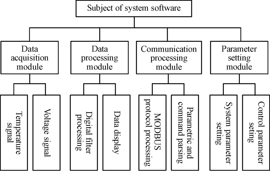
Fig.7 Overa IIstruc tu re b Iock diag ram of the softw are
The data processingmodule filters the sampled temperature and voltage data for display and alarm detection.The communication processing module uses MODBUSprotocol RTUmode to complete transmission of real-time data and operation state between themonitoring device and the remote host.
4.2 Voltage and temperature acquisition of electrolytic cell
The voltage and temperature of electrolytic cell are sampled at different sampling rates,which can be set remotely through the network tomeet different application requirements.Set the PWM output frequency of TIM1 to start the AD7606d conversion,and complete the reading of conversion data in the interrupt of EXINT1[6].The reading of the cell temperature is realized by the data acquisition task.The data read through the single bus contains the pre-written sensor bit number,thus the corresponding temperature parameters of the electrolytic cell can be obtained.The flow chart of the voltage and temperature acquisition task is shown in Fig.7.
4.3 The design of data communication protocol
Themain task of communication processing is to analyze and control the protocol frame under MODBUS protocol RTUmode[7].
MODBUS protocol read-only area contains 8 channel cell voltage,temperature and the equipment running status information.The voltage parameters LSB is 1mv,the temperature parameters LSB is 0.1℃.The read-only region parameters are obtained by MODBUS no.4 function.MODBUS no.3 function can monitor the device’s operation mode,acquisition rate,calibration and other functions.The system communication baud rate is set as115 200 bps to realize fast data exchange.The parameter address table is shown in Table 1.

Fig.8 FIow chart of the vo Itage and tem perature acquisition task

Tab Ie 1 The param eter add ress tab Ie
5 Conclusions
The system designed in this paper can monitor the voltage and temperature of the electrolytic cell in real time,and the signal detection device can sample the temperature and voltage of the electrolytic cell in 8 channels.Bymeans of isolated power supply transfor-mation and single bus isolated driving technology,the anti-interference ability is greatly improved and the signal precision ismaintained.The isolation and filtering technology of DC/DC power supply is adopted to ensure the security and stability of the design.TVS and self-recovery insurance technology are adopted for over-voltage and over-current,which can effectively suppress the surge interference.
The voltage precision in the system is±5 mV,the temperature precision is±0.5℃.The system has digital display,curve display,data recording,alarm and analysis functions,and cell voltage short circuit alarm indication.After applying in the field,the system runs reliably and stably and has a high application value.
- 机床与液压的其它文章
- Decoupling control of single DOF supporting system ofmagnetic-liquid double suspension bearing
- Influence of the thermal effect on the sealing performance of the hydraulic combined dynam ic seal
- Dynam ic GRNNmodel of hydraulic system fault detection based on the internet of things technology
- Form ing modeling and sensitivity analysis of sandwich composites
- Research of aerodynam ic characteristics of heavy commercial vehicles under crosswind for different urban road layout
- Design ofmulti-parameter ultrasonic measuring instrument for fluid

