Decoupling control of single DOF supporting system ofmagnetic-liquid double suspension bearing
Jian-hua ZHAO,Guo-ji ZHANG,Jun-bo CAO,Dian-rong GAO,Guo-jun DU
(1 College of Civil Engineering and Mechanics,Yanshan University,Qinhuangdao 066004,China)
(2 Fluid Power Transmission and Control Laboratory,Yanshan University,Qinhuangdao 066004,China)
(3 Jiangsu Provincial Key Laboratory of Advanced Manufacture and Process for Marine Mechanical Equipment,Zhenjiang 212003,China)
Abstract:With themagnetic suspension as themain method and hydrostatic bearing as the secondary one,the bearing capacity and stiffness can be improved substantially.Magnetic-Liquid Double Suspension Bearing(MLDSB)is suitable for the occasions ofmedium-speed overload,and has high stability and long service life.Due to small film thickness,strong damping,positive stiffness and repulsion of hydrostatic bearing system,and large air gap,weak damping,negative stiffness and suction ofmagnetic suspension system,the operation stability ofMLDSB can be reduced sharply by the coupling and the interference between two bearing system.In this paper,the Magnetic-Liquid coupling characteristic of single DOF bearing system is analyzed,the producemechanism of coupling force is revealed,and then the decoupling controller can be designed.Firstly,the structure of MLDSB,themechanical behavior and the adjusting principle of single DOF bearing system are presented.Then,themathematicalmodel of single DOF bearing system is established,and the coupling characteristic and influence law between Magnetic-Liquid bearing systems can be revealed.Finally,Similar Feed-Forward Decoupling Controller and Diagonal-Matrix Decoupling Controller are designed,and the decoupling effect of two controller with Simulink modules can be contrasted and analyzed.The results show that two decoupling controllers can reduce the coupling degree between Magnetic-Liquid bearing systems,but Similar Feed-Forward Decoupling Controller ismore suitable for the decoupling controller of MLDSBwith the high operation stability and the accuracy.The research in the paper can provide the theoretical reference for the stable control of MLDSB.
Key words:Magnetic-liquid double suspension bearing,Single DOF bearing system,Force decoupling control,Similar feed-forward decoupling controller,Diagonal-matrix decoupling controller
1 Introduction
Under the premise of not affecting themagnetic suspension force,hydrostatic bearing system is introduced intomagnetic suspension bearing toform a novel bearing system Magnetic Liquid Double Suspension Bearing(MLDSB),so its bearing capacity and stiffness can be increased sharply.
Due to no direct friction,high stiffness and strong bearing capacity,the operation stability and service life can be improved sharply,and then it is suitable for the fields of deep-sea exploration,hydropower generation and so on,special for the occasions of medium-speed overload and frequent starting[1].
The structure of MLDSB can be shown as Fig.1-Fig.2.
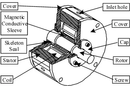
Fig.1 Sem i-isometric view of MLDSB
MLDSB is composed of cover,cap,magnetic conductive sleeve(Cold-Rolled Non-Oriented Silicon Steel Sheet+Chrome Plated),coil,stator(Cold-Rolled Non-Oriented Silicon Steel+Chrome Plated),rotor,and so on.Eight poles are circumferentially distributed in MLDSB.Two adjacent opposite poles are a pair of poles,and the magnetic loop and magnetic force are generated between themagnetic poles and magnetic conductive sleeve.There are inlet hole and bearing cavity inside themagnetic pole,and the hydrostatic force can be generated when the lubricant flows through the gap between themagnetic pole and magnetic conductive sleeve[2].

Fig.2 Fu II-sec tions drawing of MLDSB
Due to small film thickness,strong damping,positive stiffness and repulsion of the hydrostatic bearing system,and the large air gap,weak damping,negative stiffness and suction of the magnetic suspension system,the operation stability of MLDSB can be reduced sharply by the coupling and the interference between two bearing system[3-4].
Recently,coupling property of themultiple degrees of freedom ofmagnetic suspension bearing and fluidsolid coupling characteristics of hydrostatic bearing had been studied deeply by lots of scholars who have got fruitful achievements.
Zong M et al.[5]investigated the reason of the coupling problem of electromagnetic force between two degrees of freedom in a PM biased radial magnetic bearingwith four poles.Strategy and feedforward compensator decoupling algorithm for the PM biased radial magnetic bearing was presented.Through comparing and analyzing the electromagnetic force and control current before and after decoupling control showed that feed-forward compensation decoupling algorithm proposed was feasible.
Zhao H Y and Zhu C S[6]showed a feed-forward decoupling control formagnetically suspended rigid rotor.Numerical simulations and experiment results showed that the radial four degree-of-freedom coupling system for the AMB-rigid rotor can be completely decoupled intofour single degree-of-freedom systems by the feed-forward decoupling controller.
Chen L L et al.[7]showed a control strategy based on inverse system decoupling and improved two degree of freedom(2-DOF)control.It was shown that the control strategy proposed can stably suspend the AMB high-speed flywheel rotor system and effectively suppress its vibrations,with the advantages of high stability,strong robustness,and good ability of against noise.
Tao SW et al.[8]applied fluid-structure coupling principle and static pressure supporting theory,dynamic characteristics of slipper bottom film were studied,and the finite element software ANSYS had been used for simulating calculation of fluid-structure coupling between slipper bottom and film.It showed that compare to the circumstancewhen the plunger translated from low pressure region to high pressure region,there was significant difference in the circumstance from high pressure region to low pressure region.
In conclusion,many scholars at home and abroad devoted to the electromechanical coupling characteristic ofmagnetic suspension.However,there are no relevant research about the decoupling and control of magnetic-liquid coupling system which is the basic premise and inner core of stable supporting and operation of MLDSB.So the dynamic equation of single DOF bearing system is established in the paper,and the coupling rule of magnetic-liquid system is revealed.And then Similar Feed-Forward Decoupling Controller and Diagonal-Matrix Decoupling Controller are designed,and the decoupling effect of two controllers with Simulink modules can be contrasted and analyzed.
2 Structure of single DOF supporting system
The hydrostatic force and magnetic force of two adjacent opposite poles are equal respectively,so they are called a pair of poles,and then the upper and lower oppositemagnetic pole pairs and the supporting cavity are a unit for analysis called“supporting unite”.
The single DOF vertical bearing system is taken as the research object,and it is composed of upper supporting unit,lower supporting unit and rotor as shown as Fig.3.
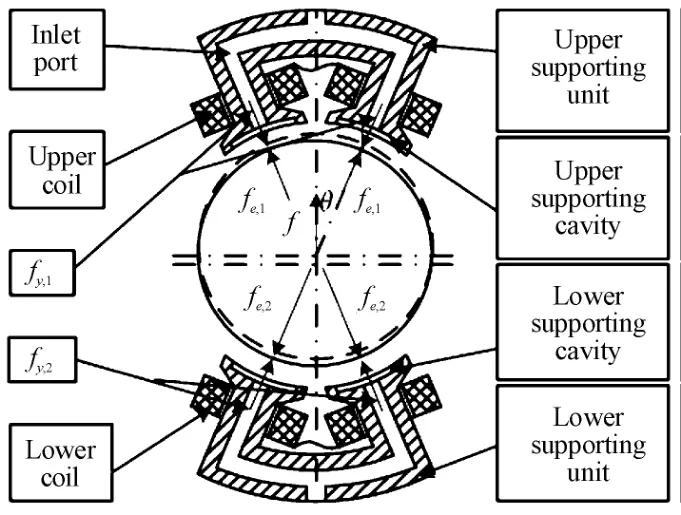
Fig.3 Forcediag ram of sing DOF suppo rting system
The adjustment principle of MLDSB is shown as Fig.4.There are coupling and interference between the magnetic supporting and hydrostatic supporting system which are controlled by the differentialmode,and the nonlinear characteristic and is increased,and then the operation stability of MLDSB can be reduced sharply[9].
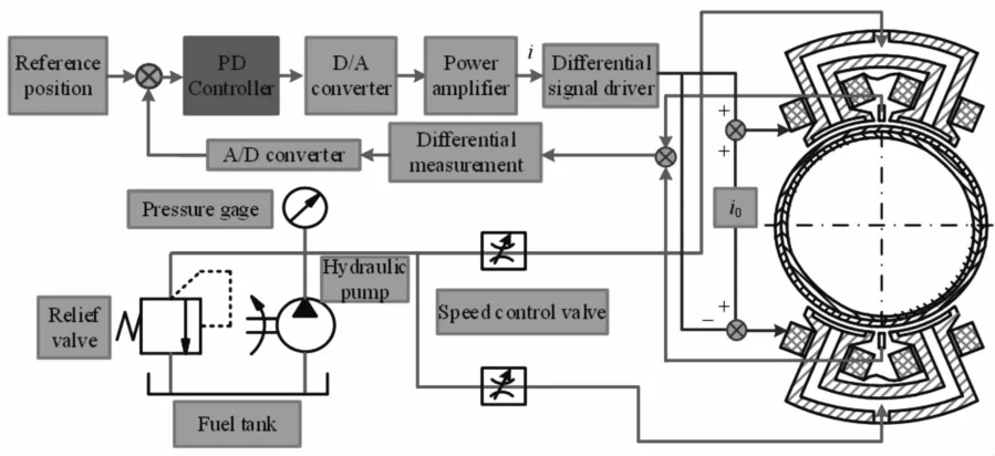
Fig.4 Sing Ie DOF supporting system of MLDSB
3 M athem atical m odel of single DOF supporting system
For studying the supporting characteristics of MLDSB,there are some following assumptions[9-11]:
(1)Flow state of lubricant is laminar,and inertial force of lubricant is ignored.
(2)The viscosity-pressure characteristics is ignored.
(3)The leakage of magnetic flux of the winding can be ignored.
(4)Themagnetic resistance between iron core and rotor is ignored,and then themagnetomotive force is assumed to act only on the air gap.
(5)The effect of hysteresis and eddy current of magnetic materials can be ignored.
(6)The supporting surface can be assumed as the rigid body.
(7)The weight of the rotor can be ignored.
3.1 Transfer function of single DOF supporting system
The dynamic equation of MLDSB can be shown as follows[10]:

Wheremismass of rotor(kg);feismagnetic force of magnetic pole(N).

fyis hydrostatic force of bearing cavity(N).

3.2 Choice of design parameters
The design parameters of MLDSB are shown as Table 1.
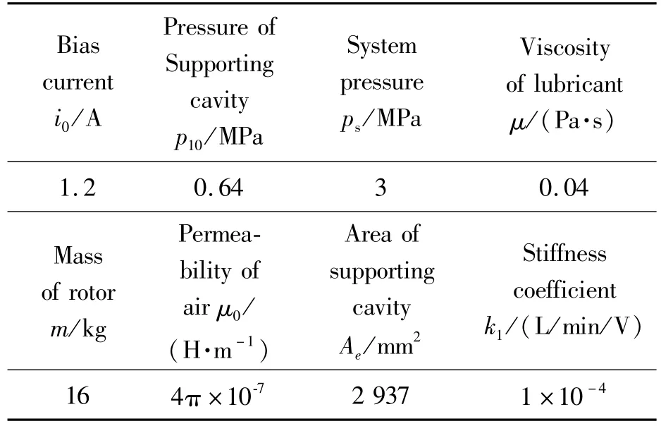
Tab Ie 1 Design param eters of MLDSB

Continued Table
3.3 State equation of single DOF supporting system
Eq.1 can be solved with the linearization and Laplace Translation,and then state equation of transfer function in which the input are control currenticof coil and control voltageuof proportional valve and the output aremagnetic forceFeand hydrostatic forceFycan be shown as follows:

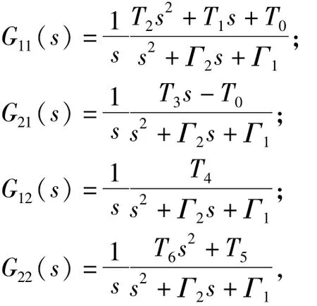
Eq.2 can be conveyed into the form of translation equation as follows:

Where

4 Decoup ling strategy of single DOF supporting system
4.1 Similar feed-forward decoupling strategy
The similar feed-forward decoupling strategy of single DOF supporting system can be shown as Fig.5.The input and output are r and y,and the controller and compensated decoupling device are Gl c(s)and Nl(s),and then the identificationmodel and convertermatrix are Gl(s)and Ml(s).

Fig.5 Princip Ie of Sim iIar Feed-Forward Decoup Iing
Based on Fig.5,r,y,Gl c(s),Nl(s),Ul(s)and Ml(s)can be shown as follows:
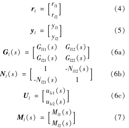
In the nominal case,Eq.6 can be shown as follows:

Arranging Eq.8:
The Similar Feed-Forward Decoupling device can be shown as follows:
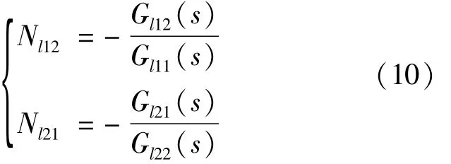
Arranging Eq.10,the transfer function Gf(s)after decoupling process can be obtained:

After similar feed-forward decoupling process,identification model Gl(s)is the form of diagonalmatrix,and the coupling characteristic between the magnetic and liquid control channel can be eliminated.
4.2 Diagonal-matrix decoupling strategy
The diagonal-matrix decoupling strategy of single DOF supporting system can be shown as Fig.6.The input and output are r(s)and y(s),and the controller and compensated decoupling device are Gd c(s)and Nd(s),and then the identification model and convertermatrix are Gd(s)and Md(s).
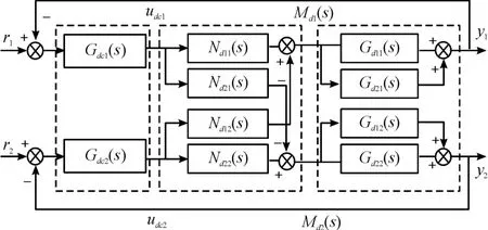
Fig.6 Princip Ie of diagona I-m atrix decoup Iing
Identificationmodel Gd(s)and targetmatrix Gm(s)can be shown as follows:

Tips:Gm(s)must be nonsingularmatrix.
And the decoupling devicematrix can be shown as follows:

Arranging Eq.14:
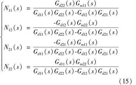
After diagonal-matrix decoupling process,identification model Gd(s)is the form of diagonal matrix,and the coupling characteristic between the magnetic and liquid control channel can be eliminated.
4.3 Analysis on decoupling effect
4.3.1 Analysis of hydrostatic and magnetic forcewhen proportional valve’s voltage changes
With the coil currentunchanged,the voltage of proportional valve is adjusted(Square wave load is applied,starting time is1 s,the cycle is1 s,the amplitude is1 V,as shown as Fig.7),and then the curves ofmagnetic force and hydrostatic force can be shown as Fig.8-Fig.9.

Fig.7 Input signa Iof coiIand p roportiona Iva Ive
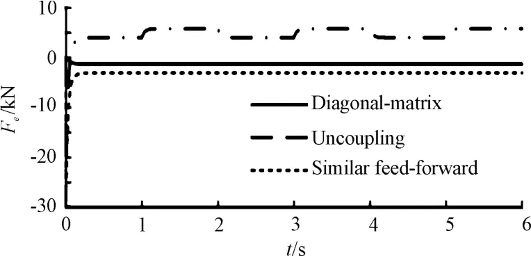
Fig.8 Curves ofm agnetic force
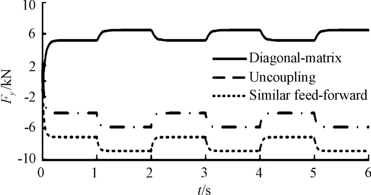
Fig.9 Curves of hyd rostatic force
According to Fig.8 and Fig.9,without the decoupling controller,the periodical varying(4.051~5.823 kN)of magnetic force can be caused by the changing hydrostatic force,and then there are coupling and interference between magnetic suspension system and hydrostatic supporting system.
Themagnetic force can remain unchanged with two decoupling controllerswhen hydrostatic supporting system changes,and then it is constantly-1.288 kN with Diagonal-Matrix Decoupling Strategy while constantly-3.039 kN with Similar Feed-Forward Decoupling Strategy.So the coupling and interference between two supporting systems can be eliminated.
The characteristics of the output can vary with the different targetmatrix Gm(s).The targetmatrix Gm(s)in the paper is shown as follows:


Adjusting timets,delaying timetdand ErrorX(i),RateM(i)of system bias can be taken as characteristics indexes,and the mathematical model can be shown as follows:
(1)Adjusting timets:the minimum time for the response curve to reach and remain within the permissible error range.
(2)Delaying timetd:the response curve from zero to 50%of the steady state.
(3)ErrorX(i):

Where,iis the number of cycles after stabilization,i=3;Fmax(i),Fmin(i)are the maximum value and minimum value in one stability period.
(4)Bias RateM:

Where,F0is the stable value of initial stage.
The result of hydrostatic force characteristics indexes can be shown as Table 2.
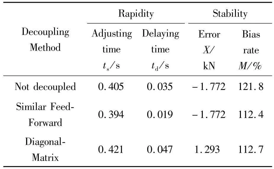
Tab Ie 2 Resu It of hyd rostatic force characteristics indexes
According to Table 2,the bias rateMof hydrostatic force is smaller by Similar Feed-Forward Decoupling Controller.As for the adjusting timets(s)and Delaying timetd(s),the Similar Feed-Forward Decoupling Controller is faster.In short,Similar Feed-Forward Decoupling Controller is suitable for decoupling and control of single DOF supporting system of MLDSB.4.3.2 Analysis of hydrostatic and magnetic forcewhen the coil current changes
With the voltage of proportional valve unchanged,the current of coil is adjusted(Square wave load is applied,starting time is1 s,the cycle is1 s,the amplitude is 1 A as shown as Fig.10),and then the curves ofmagnetic force and hydrostatic force can be shown as Fig.11-Fig.12.
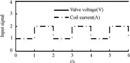
Fig.10 Input signa Iof coiIand p roportiona IvaIve
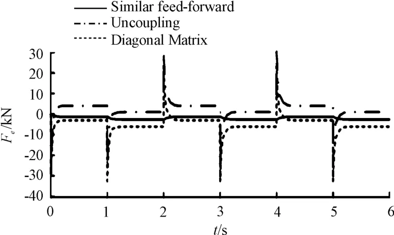
Fig.11 Curves of magnetic force
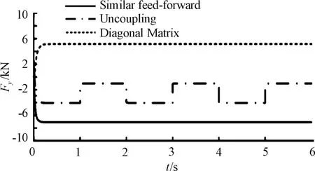
Fig.12 Curves of hydrostatic force
According to Fig.11 and Fig.12,without the decoupling controller,the periodical varying(-1.013~4.051 kN)of hydrostatic force can be caused by the changingmagnetic force,and then there are coupling and interference between magnetic suspension system and hydrostatic supporting system.
The hydrostatic force can remain unchanged with two decoupling controllers when magnetic supporting system changes,and then it is constantly 5.170 kN with Diagonal-Matrix Decoupling Strategy while constantly-7.090 kN with Similar Feed-Forward Decoupling Controller.So the coupling and interference between two supporting systems can be eliminated.
The result of characteristics indexes can be shown as Table 3.
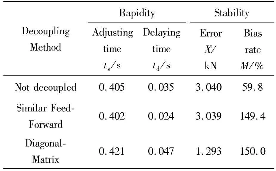
TabIe 3 Resu It of magnetic force characteristics indexes
According to Table 3,the bias rateMof magnetic force is smaller by Similar Feed-Forward Decoupling Controller.As for the adjusting timets(s)and Delaying timetd(s),Similar Feed-Forward Decoupling Controller is faster.In short,Similar Feed-Forward Decoupling Controller is suitable for decoupling and control of single DOF supporting system of MLDSB.
5 Conclusion
(1)Coupling effect between magnetic-hydrostatic supporting systems can be eliminated with both Similar Feed-Forward Decoupling Controller and Diagonal-Matrix Decoupling Controller.
(2)Similar Feed-Forward Decoupling Controller is suitable for decoupling and control of single DOF supporting system of MLDSB.
- 机床与液压的其它文章
- Influence of the thermal effect on the sealing performance of the hydraulic combined dynam ic seal
- Dynam ic GRNNmodel of hydraulic system fault detection based on the internet of things technology
- Form ing modeling and sensitivity analysis of sandwich composites
- Research of aerodynam ic characteristics of heavy commercial vehicles under crosswind for different urban road layout
- Design ofmulti-parameter ultrasonic measuring instrument for fluid
- Maintenance level decision-making for aeroengine based on large margin nearest neighbor algorithm

