Design ofmulti-parameter ultrasonic measuring instrument for fluid
Xing-hong ZHANG,Zhi-zhong ZHANG,Xiang-yu HOU,Yi-rui LI,San LI
(Liang-Jiang International College,Chongqing University of Technology,Chongqing 401135,China)
Abstract:In order to solve the problem of singlemeasurement parameters of fluid tester,amethod ofmeasuring fluid multiparameter by ultrasonic technique is proposed.When the propagation distance is constant,the volume flow,density,and mass flow of the fluid are obtained indirectly by using the propagation velocity of ultrasonic waves in the fluid.Because the parameters such as fluid flow and density are affected by the temperature,the temperature signal is used as the reference signal in the design to compensate the parameters in real time.At the same time,using FPGA as the control core to achieve high-velocity signal acquisition and processing,and using software interpolation algorithm to accurately realize the precise calculation of ultrasonic propagation time,the measurement results can bemore stable and reliable.
Key words:Flow measurement,Densitymeasurement,FPGA,Time of transmission
The fluid volume flow,density,and mass flow are the basic parameters of the fluid.Themeasurement of these parameters not only exists in fluid mechanics,but also appears in factories,scientific research institutions and inspection departments[1].In traditional temperature measuring instruments, thermocouples,thermal resistors,infrared thermometers and other instruments are usually used to measure temperature;float,vibration,and optical densitymeters are used to measure density;differential pressure flow meters and electromagnetic flow meters are used to measure flow rate.With the development of electronic technology,the requirements for the realization function,processing velocity,and measurement accuracy of measurement and control systems in production and research are also constantly improving.It is hoped that the measurement equipment can carry out unified testing on many parameters,and even the measurement and control system can realize the remote measurement of the measurement parameters.Traditional measuring instruments are simple to operate and easy to maintain.However,it can only measure a single signal.When the user needs to perform a comprehensive analysis of multiple measurement parameters,the measurement system cannot accuratelymeasure all of these parameters.Ultrasonic measuring technology is a new type of measurement technology developed in recent years.Because of its low power consumption,high precision and wide range and other advantages,it is widely used in the detection of various fluid parameters[2].But there are few academic papers about multi-parameter ultrasonic measuring instruments.Therefore,it is necessary to design amulti-parameter ultrasonicmeasuring instrumentof volume flow,density and mass flow in engineering practice.
The three parameters of fluid volume flow,density,and mass flow have correspondingmeasurementmethods.In this paper,ultrasonic technology is be used to obtain these parameters at the same time.Ultrasonic technology has the characteristics of highmeasurement accuracy,widemeasurement range and flexible installation,which can effectively solve the problem of low integration of traditional instruments.This article uses FPGA’s high-velocity hardware acquisition system to collect data.Various sensors installed in the system can realize real-time measurement of parameters such as volume flow,density and mass flow.And it can be intuitively displayed on the display.This makes the fluid measurement system more flexible and reliable.
1 Working p rincip le of fluid m u lti-param eter u ltrasonic m easu ring instrum ent for fluid
1.1 Measurement principle
The design ofmulti-parameter ultrasonic measuring instrument for fluid is based on the design principle of time difference ultrasonic volume flowmeter.Time difference ultrasonic flowmeter is the application of ultrasonic wave in the field ofmeasurement.Some parameters of the ultrasonic wave propagating in the fluid will change due to the information of the medium.Therefore,the information can be used to indirectly measure the parameter value of the fluid.As shown in Fig.1,bymeasuring the propagation time of ultrasonic waves in the downstream and upstream of the pipeline[3].Using forward and backward flow timemathematical operations to obtain the fluid velocity and volume flow.Through the relationship between the velocity of ultrasonic waves in still water and the density of the fluid,the second parameter density of the fluid is measured.Finally,the productof the volume flow rate and the density is used to obtain themass flow rate of the fluid,so that the volume flow rate,density,and mass flow rate of the fluid can bemeasured.

Fig.1.Princip Ie diagram ofm u Iti-param eter u Itrasonic measurem ent of fIuid
1.1.1 Volume flow measurement
In Fig.1,the propagation of ultrasonic from transducer A to transducer B is the forward flow process,with the propagation time oft1,and the propagation of ultrasonic from transducer B to transducer A is the reverse flow process,with the propagation time oft2.If the propagation velocity of the ultrasonic wave in still water isc,the fluid velocity isv,the distance between the transmitting transducer and the receiving transducer isL,and the angle between the flow direction of the fluid and the sound channel isθ,then[4]:

The time difference between ultrasonic forward and reverse flow is

The time product of ultrasonic forward and reverse flow is

The expression of flow velocityvcan be obtained by combining equation(3)and(4)[5]:

Therefore,the expression of volume flowqvis

It can be seen from equation(5)that,during the calculation of the flow velocity,the propagation velocitycof ultrasonic wave in still water is eliminated.However,the propagation velocity c of ultrasonic waves in still water is easily affected by the ambient temperature.Therefore,it is not necessary to consider the effect of temperature on flow velocity after omitting the propagation velocityc.This simplifies the temperature correction process of measurement results.The fluid volume can be calculated only by measuring the time of forward and reverse flow propagation,which improves themeasurement accuracy.
1.1.2 Fluid densitymeasurement
Different fluid media will affect the propagation velocity of ultrasonic waves.The density of the fluidmedium is different,and the propagation velocity of ultrasonic waves is different.The relationship between the propagation velocity of ultrasonic waves and the density of fluid is as follows:

Kis the coefficient of compressibility.The coefficient of compressibility of differentmedia can be obtained by looking up the table.The density of the fluid can be obtained by measuring the propagation velocity of ultrasonic in the fluid.The value ofKwill change with differentmedium and temperature variation.The coefficient of compressibility of different medium is listed in Table 1[6].
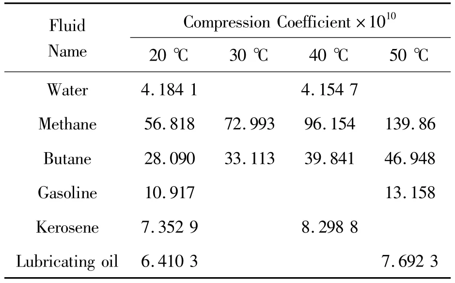
Tab Ie 1 Com p ressibiIity coefficient of differentmedia
According to equation(1)and equation(2),the propagation time of ultrasonic forward and reverse flow can be obtained.

The propagation velocity of ultrasound at rest is

In combination with equation(7),the calculation formula of fluid density can be obtained as follows

1.1.3 Mass flow measurement
There are twomain methods[7]of ultrasonic mass flow measurement:the directand the indirectmethod.This design uses an indirectmeasurementmethod.It is based on volume flow measurement and multiplies the calculated density to obtain the mass flow.The calculation results are as follows:

1.2 Multichannel structure design ofmeasuring instrument
The structure of ultrasonicmeasuring instrument can be divided intomono and multi-channel.The division is based on the different pairs of the transducers[3].A channel composed of only a pair of transducers is called amonophonic ultrasonic measuring instrument.A channel composed of two pairs ormore of transducers is called a multi-channel ultrasonic measuring instrument.The purpose of designing multi-channel structure is to solve the limitation of monophonic measurement and to avoid large deviation ofmeasurement results caused by external conditions such as random errors and uneven distribution of flow velocity.Use the average velocity of sound of different channels to get the final result.It can fully reflect the velocity of ultrasonic waves in different channels,and the measurement accuracy is higher.The calculation formula of velocity ofmulti-channel ultrasonic measuring instrument is as follows[8]:

wirepresents theweighted integral coefficient of channeli.If the cross-sectional area of the pipeline is denoted byA,the volume flow of the fluid is

Themass flow is

In theory,the greater the number of channels,the higher the accuracy of themeasurement results.However,in reality,too many channels have little effect on improving accuracy,but it increases the cost and design difficulty.Therefore,the number of channels should be selected according to the actual situation.Considering many factors such as design cost,hardware circuit complexity,design difficulty and so on.This paper chooses the two-channel measurement method.Common installation methods are shown in Fig.2.Each channel is equipped with a pair of ultrasonic transducers.Each transducer can both transmit and receive ultrasonic waves.Therefore each channel can complete the entire transmission and reception process.
2 Scheme design
According to the data,the propagation velocity of ultrasonic in water is about 1 496 m/s and the distance of the pipe diameter is300mm.The propagation velocity of ultrasonic waves in water is very fast,which requires the processor to process the signal at a high velocity.Combined with numerous literature analysis,field programmable gate array(FPGA)has the advantages of high velocity and good stability.It is more and more widely used in ultrasonic products.Domestic and foreign scholars have also done a lot of research work on ultrasonicmeasurement product base on FPGA.FPGA can process all kinds of complex digital signals and store the data in its internalmemory to achieve high-velocity access to thememory.
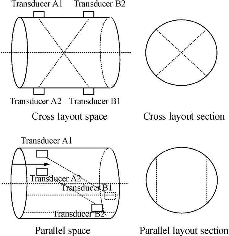
Fig.2 Mu Iti-channe I u Itrasonic m easuring instrum ent channe IIayout
In summary,this research designs a core device scheme based on FPGA.FPGA can realize the generation of ultrasonic signals,channel control,selection of forward and reverse flow mode,sampling and storage of ultrasonic signals and echo signals.As shown in Fig.3.The scheme includes:Selection of measurementmethods,determination of FPGA core devices.Themain body of the scheme is divided into hardware design and software design,focusing on the design of the transducer,the high-velocity signal sampling and the processing circuit design,and the algorithm design of themeasurement of the start time and the end time of ultrasonic propagation.A special software interpolation algorithm is used to determine the end pointof the ultrasonic propagation time.
3 Circuit design
3.1 Hardware circuit design
The hardware structure of the system is shown in Fig.4.It ismainly composed of driving circuit,temperature measuring circuit,signal processing circuit and display circuit.The driving circuitmainly comprises pulse signal generating module,D/A conversion circuit,power amplifying circuit and channel switchingmodule.The temperaturemeasuring circuitmainly completes real-time measurement of the fluid temperature.It includes temperature sensor part,filter circuit and amplification module.The signal processing circuit is a key part of the multi-parameter measurement system.It mainly includes the measurement system to control the transmission and sampling of the ultrasonic signals,the filtering the clutter signal,the amplifying the small signals,the storage of echo signals and the calculation of various parameters.The display circuit includes the keyboard,data bus and LED display.
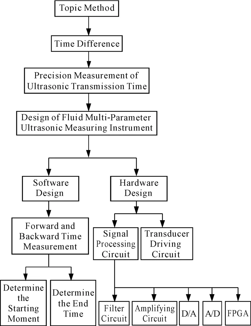
Fig.3 System schem e design
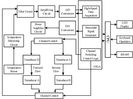
Fig.4 System hardware structure diagram
When measuring the ultrasonic forward and reverse flow propagation time of each channel,it is processed by the time-sharingmode.Themeasurement of propagation time of each channel can work in parallel under the logic control of FPGA,avoiding themutual interference of ultrasonic signals caused by simultaneous operation ofmultiple channels,so it can increase reliability.The system works as follows[9]:
First,FPGA generates the excitation signal to drive the transducer to generate ultrasonic wave,and controls at the same time controls the A/D converter to sample the ultrasonic echo signal.When the ultrasonic signal propagates through the fluid and reaches the receiving end,at this time,the amplitude of the received signal is small and containsmany invalid signals.It needs to be filtered and stored in the storage area inside the FPGA.When the sampling ends,the CPU reads the sampling data and performs analysis and processing.Finally,the calculation result is transmitted to the display circuit.
3.2 Software design
The purpose of the software design is to accurately calculate the propagation time of the ultrasonic in the fluid.Then the volume flow,density andmass flow of the fluid are obtained indirectly according to mathematical calculation of forward and reverse flow time.The software control process is shown in Fig.5.
The software working process is:
(1)After the system is powered on,first complete the initialization process,including parameter clearing,clock setting,system self-test,etc.
(2)The system selects the channel,and the gating needs tomeasure the channel and set the forward and reverse flow workingmode of the channel transducer.If the forward flow measurement mode of the first channel is selected,the temperaturemeasurement circuit first completes the measurement of the current temperature and stores the temperature value in the register.The CPU controls FPGA to send out driving signals to drive corresponding transducers to emit ultrasonic signals.At the same time,control the A/D conversion circuit to sample the data and store the sampled data in the RAM area,and then turn off the excitation signal.After sampling,the CPU reads data from the storage area and analyzes the sampled data to obtain the time value of forward flow propagation.
(3)After the forward flow time measurement is completed,switch the workingmode of the transducer and start the reverse flow measurement.Follow the above steps to complete the sending,collection and processing of reverse flow measurement data.
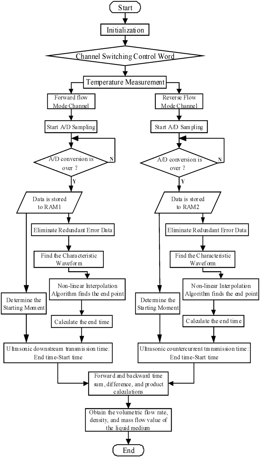
Fig.5 Software design p rocess
(4)Switch channels to completemultiple forward and reverse ultrasonic transmission time measurements,average the measurement results,and calculate the final flow rate value and density.
3.3 Calculation of ultrasonic propagation time
As shown in Fig.6,the time corresponding to the zero-crossing point of the eighth drive signal is the starting point of the ultrasound control by the FPGA.The end point of the ultrasonic propagation time is the requested time,corresponding to the zero-crossing point of the received maximum waveform[8].
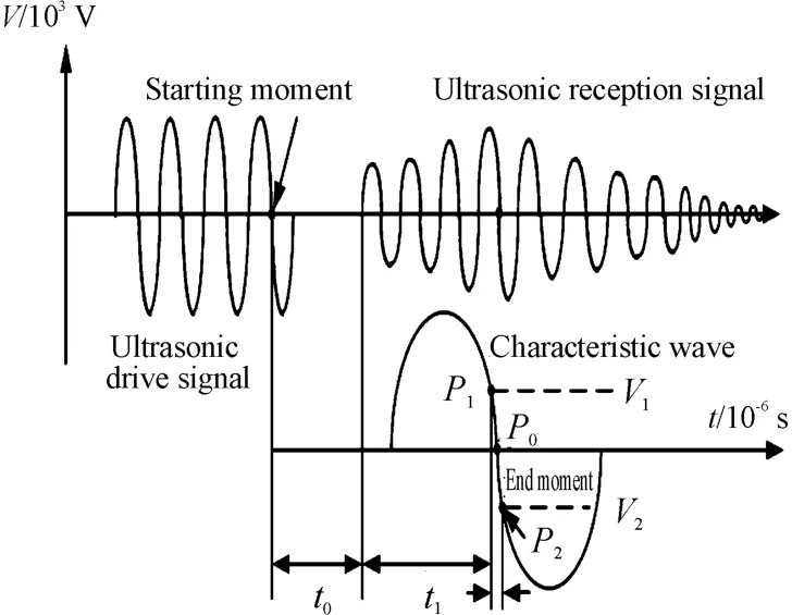
Fig.6 Schem atic diagram of u Itrasonic p ropagation time
Let A/D sample frequency be represented by symbolfA/D.The sampling circuit starts counting after receiving the sampling command.If the first sampling point is recorded as1,the number of samples from the first point to the sampling pointP1isN.The sampling values of sampling pointsP1andP2are respectivelyV1andV2,and the corresponding time are respectivelyt1andt2.The time atwhichP0is located is the desired end time,and the time interval betweenP0andP1ist2.Then the calculation formula of ultrasonic propagation time is[10]:

3.4 Measurement accuracy analysis
The design of the fluid multi-parameter ultrasonic measuring instrument is to use the propagation time of the ultrasonic waves in the fluid in the forward and reverse directions to indirectly obtain the flow velocity,volume flow,density and mass flow.In the process of measuring the propagation time,due to human factors,environmental factors and the system itself all have a certain influence on the measurement results,so it is necessary to analyze and correct the measurement results[11].
3.4.1 The revision of flow velocity distribution

In equation(5),the flow velocity derivation formula is carried out under ideal conditionswhere the flow velocity of the fluid is evenly distributed.But in actual operation,the fluid flow is not uniform.Therefore,themeasurement datamust be corrected[5].The correction formula is as follows[9]:kis the flow velocity distribution coefficient.Based on fluid mechanics knowledge,there is a functional relationship between the correction coefficientkand the Reynolds number of the velocity.The ratio of inertia forceFgand viscosity forceFmin fluid flow is Reynolds number,the symbol isRe,it is an important parameter to characterize fluid flow characteristics.When the fluid is laminar statue(the Reynolds number is less than 2320),the flow ratemeasured by the ultrasonicmeasuring instrument is3 or 4 times the actual fluid flow rate,i.e.[12]:

When the Reynolds number is greater than 2320,the fluid is in a turbulent state.The relationship between the flow rate distribution and the Reynolds number is as follows,and the correction coefficient value can be determined based on the Reynolds number.

When the fluid motion state is between laminar flow state and turbulent flow state[13]:

3.4.2 Temperature correction
The propagation velocity of ultrasonic in the fluid will change with the change of temperature.Taking water as an example,the trend of ultrasonic propagation velocity with temperature is shown in Fig.7.When the temperature rises,the propagation velocity presents a law of increasing first and then decreasing in a nonlinear form.Since the value of ultrasonic propagation velocity is omitted in the calculation of flow velocity,the influence of temperature on volume flow can be neglected.This papermainly studies the relationship between temperature and fluid density[14].
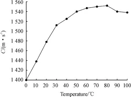
Fig.7 Re Iationship betw een u Itrasonic p ropagation veIocity and water tem perature
Because the volume change of the object is propor-tional to the temperature,βrepresents the volume change of the medium volume with temperature,that is,the volume change amount for each temperature increase of 1℃compared with the volume at 0℃.Therefore,the volume when themedia temperature ist℃ is as follows:

If the temperature ist1,the volume of the fluid isVt1,and the temperature ist2,the volume changes toVt2,including:

Suppose the density of the object at temperaturet1andt2isρ1andρ2respectively,if themass of the object ism,there are:
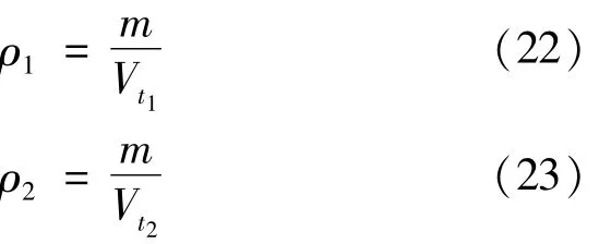
By substituting intoρ1andρ2,we can get:

Neglecting theβ2term,the above formula can be approximately written as:

If the ratio ofρ1-ρ2andt2-t1represents the temperature correction value of the density,and represents the correction value,the density of the medium after the temperature change is:

It can be expressed asβ:

It can be seen from the above that the volume increase of the object is proportional to the temperature increase,and themeasured density can be corrected.
3.4.3 Resolution analysis
According to equation(15),the resolution at the end point is[15]:

Letfube 1 MHz,A/D be 12 bit converter,sampling frequency is 32 MHz,Theoretically,there are

It can be seen from the analysis above that the parametermeasurement resolution of the ultrasonicmeasuring instrument can reach nanosecond level.It can be seen from equation(29):the resolution ofmeasurement timemainly depends onRA/Dandfu,and is proportional to them.WhenRA/Dis constant,the higher thefu,themore accurate themeasurement results are.Whenfuis constant,the higherRA/Dis,the more points are sampled in each cycle,and themore accurate the sampling is.Therefore,the accuracy of themeasurement results can be improved by increasing the ultrasonic input frequency or the number of digits of resolution of the A/D converter.
3.5 Analysis of results
Themeasurement of fluid multi-parameters is actually the measurement of ultrasonic propagation time.In this paper,using water as the fluid medium,the actual propagation time of ultrasonic in water was carried out.The experiment time is selected from 09∶00 to 12∶00 in the morning,with room temperature at 25℃and constant temperature.6 000 experimental data were measured in 3 hours.The plotted curve is shown in Fig.8.It can be seen from Fig.8:The ultrasonic propagation time has a small deviation in continuous time.The main reason is that due to the influence of temperature,the propagation time decreases slightly with increasing temperature.
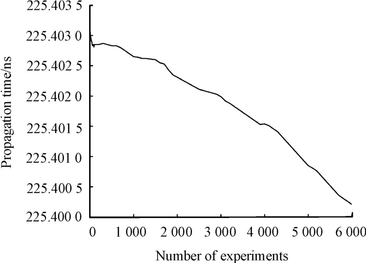
Fig.8 Continuous measurem ent of u Itrasonic p ropagation tim e
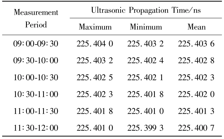
In order to accurately analyze the sampling data,all the experimental data are segmented by time,and the segmented results are shown in Table 2.
Table 2 shows that when the temperature changes within a certain range,the ultrasonic propagation time is basically stable,and the error is about1 ns.Select 300 sampling data in the last group of time in Table 2 for drawing,and the curve in Fig.9 can be obtained.It can be seen from Fig.9 that,in a certain period of time,the ultrasonic propagation time is stable,and both aremaintained at the time period of 225.403 5.In the experimental data,only a few sampling points have an error of about0.3 ns,and the q error data is close to the theoretical resolution of 0.122 ns.It shows that the design is reasonable and can achieve stable and high-precision ultrasonic propagation time measurement.
Tab Ie 2 Experimenta Idata segm ented by tim e
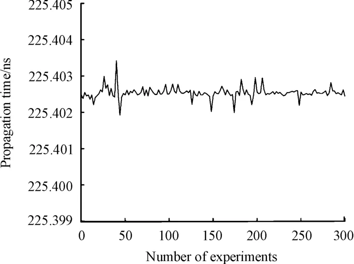
Fig.9 UItrasonic p ropagation tim e in a certain period of tim e
4 Conclusions
To solve the problem of singlemeasurement of fluid parameters,a method for measuring multi-parameters of fluid by ultrasonic technology is proposed.The features are as follows:
(1)In the two-channel measurement method,two pairs of measuring heads are evenly installed on the outside of the fluid medium container,which effectively avoids the requirements of fluid medium ofthe fluid medium on the material of the transducer.The random error caused by uneven fluid distribution is reduced,making themeasurement resultmore accurate.
(2)With themeasured fluid as the propagationmedium,when the propagation distance of the ultrasonic wave is fixed,the flow rate and density of the fluid can be obtained bymeasuring the propagation time of the ultrasonic wave in the forward and reverse flow.Different channel measurement works in time-sharing mode,which avoids cross interference of different signals.
(3)Ultrasonic propagation timemeasurement adopts software interpolation subdivision algorithm.The advantage is that timemeasurement can achieve nanosecond accuracy.
(4)With temperature as the reference signal,multisignal fusion is realized,and themeasurement results are corrected in real time to ensure the reliability of measurement.
- 机床与液压的其它文章
- Decoupling control of single DOF supporting system ofmagnetic-liquid double suspension bearing
- Influence of the thermal effect on the sealing performance of the hydraulic combined dynam ic seal
- Dynam ic GRNNmodel of hydraulic system fault detection based on the internet of things technology
- Form ing modeling and sensitivity analysis of sandwich composites
- Research of aerodynam ic characteristics of heavy commercial vehicles under crosswind for different urban road layout
- Maintenance level decision-making for aeroengine based on large margin nearest neighbor algorithm

