
Influence of towing speed on effectiveness of rolling dynamic compaction
2020-02-18 03:07BrendnScottMrkJksPeterMitchell
Brendn T. Scott, Mrk B. Jks, Peter W. Mitchell,b
a School of Civil, Environmental and Mining Engineering, The University of Adelaide, Adelaide, South Australia, 5005, Australia
b Aurecon, Adelaide, South Australia, 5000, Australia
Keywords:Rolling dynamic compaction (RDC)Optimum towing speed Ground improvement
A B S T R A C T The influence of towing speed on the effectiveness of the 4-sided impact roller using earth pressure cells(EPCs) is investigated. Two field trials were undertaken; the first trial used three EPCs placed at varying depths between 0.5 m and 1.5 m with towing speeds of 9-12 km/h.The second used three EPCs placed at a uniform depth of 0.8 m,with towing speeds of 5-15 km/h.The findings from the two trials confirmed that towing speed influences the pressure imparted to the ground and hence compactive effort. This paper proposes that the energy imparted to the ground is best described in terms of work done,which is the sum of the change in both potential and kinetic energies. Current practice of using either kinetic energy or gravitational potential energy should be avoided as neither can accurately quantify rolling dynamic compaction (RDC) when towing speed is varied.
1. Introduction
Improving the ground is a fundamental and essential part of civil construction.Compaction is a prevalent ground improvement technique that involves increasing the density of soil by means of mechanically applied energy to increase shear strength and stiffness or reduce permeability. This paper is concerned with rolling dynamic compaction (RDC) which involves traversing the ground with a non-circular roller. Typical module designs have 3, 4 or 5 sides.As the module rotates,it imparts energy to the soil as it falls and impacts the ground.More introductory information pertaining to RDC is included in Scott and Jaksa (2015) and Ranasinghe et al.(2017).
At filled sites containing significant soil variability, it can be difficult to quantify the effect of a single variable. Similarly, the inherent soil heterogeneity of natural ground can also influence results,often making it hard to quantify the effect of towing speed alone.To overcome this limitation,two compaction trials that used homogeneous soil conditions are described in this paper.Both trials used buried earth pressure cells (EPCs) and were undertaken at a dedicated research site. Whilst replacing natural soil with fill material and conducting full-scale trials are expensive exercises,particularly where the trial is not part of a client funded project,having full control over a site enabled variables other than towing speed to be held constant.The aim of this paper is to determine the influence, if any, of towing speed on the energy imparted to the ground.
The impact roller was originally developed in South Africa with the intention of improving the properties of granular soils, in particular to identify and improve collapsing sands within 3 m below the ground surface in southern Africa (Clifford, 1978).Wolmarans and Clifford (1975) described a case study of compacting Kalahari (collapsing) sand in Rhodesia where at least 25 passes were required; layers were able to be compacted in thicknesses of up to 1.5 m and still achieve the target density. Clifford(1975) stated that the impact roller is not a finishing roller, as it over-compacts the near-surface soils, often requiring the upper 0.1-0.2 m to be compacted by rollers used for surfacing works.Ellis(1979) described that one of the main advantages of RDC was to compact cohesionless soils in thick layers; however, he cited a disadvantage that in loose soils,the near-surface soil is disturbed by RDC and must be compacted by other machines,agreeing with the results of Clifford (1975).

Fig.1. 4-sided RDC module (Broons).
The typical operating speed range of the 4-sided impact roller,as shown in Fig.1, is 9-12 km/h. Clifford (1980) stated that one of the difficulties encountered with RDC is the need for rollers to be operated at their optimum speed to ensure that sufficient energy is generated for each impact blow.In cases where the towing speed is slower than the typical range, or the module slides across the surface, Clifford (1980) found that adding a capping layer of material containing a granular/cohesive mixture could reduce lateral shearing effects and aided traction of the module for typical towing speeds. Clifford (1978) described a case study where an insufficiently thick capping layer was adopted which resulted in individual impact blows punching through to the underlying dredged fill;the site was also divided into a series of small working areas in which the roller was unable to maintain a towing speed within the typical range. According to Clifford (1978), both factors cause a reduction in speed and are the key reasons that better results could not be obtained.
Clifford (1980) discussed that there is an upper speed limit beyond which an impact blow is not delivered by the face of the module. At towing speeds greater than the typical range, Clifford(1980) stated that the roller can spin as a circular mass and only contact the ground with its corners, a condition that should be avoided. Avsar et al. (2006) described the compaction of a 22-km2reclamation area for the new Doha International Airport Project.They identified towing speed as one of the most important indicators that directly influenced the in situ dry density that could be achieved;an optimum towing speed of the 4-sided roller for that project was found to be 11 km/h. Chen et al. (2014) conducted a laboratory investigation on a scale model impact roller device in loose dry sand,by examining the effect of module weight,size and towing speed.They used a Chinese cone penetration test to confirm that towing speed was one of the most important factors contributing to the effectiveness of the impact roller.The aforementioned cases generally support the concept that towing speed influenced the effectiveness,as did the findings of Scott and Suto(2007),who stated that ground near the perimeter of a fenced site could not be improved as successfully as the rest of site due to access-related issues that reduced the towing speed of the module. This paper presents the findings of two full-scale field trials that were undertaken to quantify the effect of towing speed for the 4-sided impact roller.
2. Testing methodology
Each time the module of an impact roller strikes the ground, a pressure wave is created that travels through the soil from the surface. A key aim of the trial is to measure the loading-induced stresses below the ground due to RDC. EPCs allow real-time measurements of stresses imparted to the ground. Rinehart and Mooney (2009) successfully used Geokon Model 3500 semiconductor type EPCs in a field trial to measure dynamic loading induced from vibratory circular drum rollers. They used 100 mmdiameter cells that were 10 mm thick with normal stress measurement ranges of 250 kPa,400 kPa and 1000 kPa.The same type of cells were selected to measure the pressure imparted into the soil due to RDC, albeit 230 mm-diameter cells of 6 mm thickness with a normal stress measurement range of 6000 kPa to capture the expected higher loads from the impact roller.
It has been well documented by researchers (e.g. Weiler and Kulhawy, 1982; Rinehart and Mooney, 2009) that a buried cell can influence localised stress fields and therefore any measurements may not be representative of the true loading-induced stresses. They discussed that errors can be minimised via the choice of pressure cell design, by undertaking calibration and by the use of correct field placement techniques.Given the challenges associated with measuring in situ stress accurately, it was important to characterise the uncertainty in the measurement techniques adopted.A whole system calibration was performed both pre-and post-testing, whereby the worst-case scenario was a difference of 8.5%. This magnitude of error is generally consistent with that reported by Dave and Dasaka (2011) who compared different calibration techniques for EPCs and stated that pressure cell output could be considered reliable within an error of approximately 10%.The dynamic frequency response (peak capture) was affected by the data acquisition rate and any internal filtering used in the signal path. The data acquisition rate selected was 2000 samples per second,and the filter used was set at 800 Hz.Fast Fourier transform analysis of the data indicated that the fundamental frequency of impulses due to RDC was less than 800 Hz,confirming that the peak values were not attenuated by the adopted filter.
2.1. Trial A
A field trial was undertaken at Monarto Quarries, located approximately 60 km southeast of Adelaide, South Australia. The test site was primarily chosen because there was access to earthmoving equipment, and importantly, homogeneous quarry material was used for the field trial.An area within the quarry where the ground was flat,close to material stockpiles,yet away from quarry operations was chosen for the trial. Natural soil was removed to a depth of 1.75 m,over a plan area that was 10 m long and 5.5 m wide.Three Geokon Model 3500 EPCs were buried at nominal depths of 0.5 m,1 m and 1.5 m within the quarry fill material that was placed in seven lifts of 250 mm thickness. Bedding sand was placed immediately below and above each pressure cell to ensure horizontal placement and to prevent gravel sized particles of the fill material from damaging the cells.Each lift was wheel-rolled using a Volvo L150E loader; a vibrating plate compactor was used to compact soil within 250 mm from each EPC to prevent possible damage.
2.1.1. Material classification
The fill material placed for the trial was a crushed rock with a maximum particle size of 20 mm that was readily available and locally produced. A summary of the particle size distribution and Proctor compaction test results for Trial A is given in Table 1.For Trial A, particle size distribution (ASTM D6913-04(2009), 2009) results are the average of nine tests,and the standard(ASTM D698-12,2012)and modified(ASTM D1557-12,2012)Proctor compaction results are the average of three curves. The field moisture content (ASTM D2216-10, 2010) reported is the average of nine tests undertaken.Atterberg limit testing (ASTM D4318-10, 2010) confirmed that the fines consisted of clay of low plasticity.According to the Unified Soil Classification System(USCS),the fill material used for this compaction trial could be described as well-graded gravel(GW).
The aim of Trial A undertaken in August 2012 was to measure the loading-induced stress at three different depths for 40 passes in total;10 passes of the roller were conducted at each of the towing speeds of 9,10,11 and 12 km/h. Towing speed was controlled via the control panel in the towing unit (i.e. tractor) but was subsequently validated by dividing the distance between EPCs by thetime interval between the peak pressures that were measured.Three EPCs were used to measure the pressure imparted to the ground, each offset by one-half of one revolution of the module(2.9 m) in the forward direction of travel.Avalle et al. (2009) used buried instrumentation to capture the ground response of the 4-sided impact roller and their work found that the time during which the impulse load occurred was less than 0.1 s. They found that a sampling frequency of 2 kHz was sufficient to capture the rapid increase in pressure caused by impact from RDC and this same sampling frequency is adopted for the field trial presented in this paper. The selection of thin EPCs used in the present trial provides a much more reliable measurement of in situ soil stress than the bulky load cell used by Avalle et al. (2009), which is significantly stiffer than the surrounding soil.

Table 1 Particle size distribution, compaction and field moisture test results of 20 mm crushed rock fill material for Trials A and B.
2.1.2. Assessment of EPC results
Fig.2 presents example results of the measured pressures versus time for a single pass of the impact roller travelling across the test site.The order in which the three traces were recorded is a function of the physical placement of the EPCs in the ground; 1.5 m depth located farthest left, 1 m depth in the middle and 0.5 m farthest right.The largest peak pressure was observed for the EPC buried at 0.5 m depth, whereas the deeper pressure cells at 1 m and 1.5 m depths recorded smaller impulses, indicating that the pressure imparted into the soil reduces in magnitude and increases in area with greater depth, as expected. Fig. 3 highlights a single impact blow measured by an EPC,where a loading-induced peak pressure of 648 kPa was recorded at 0.5 m depth. Fig. 3 demonstrates the dynamic nature of RDC and the importance of adopting a 2 kHz sampling frequency is evident from the individual data points shown, given that the loading and unloading phases occur over a time period of approximately 0.045 s.

Fig. 2. Example results for a single pass of the impact roller over buried EPCs.
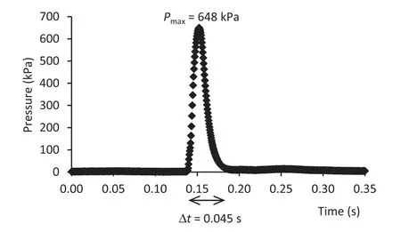
Fig. 3. Measured impulse pressure at 0.5 m depth.

Fig. 4. Measured peak pressure increasing with towing speed.
Fig. 4 presents the relationship between the measured peak pressures versus depth for each of the towing speeds examined,with an increasing trend between the peak pressure and towing speed evident for all depths measured, and a decrease in pressure with depth, as one would expect. As can be observed from these results,a clear relationship exists between measured pressure and towing speed,with the slowest speed of 9 km/h yielding the lowest pressures, and progressively increasing with greater speed. Fig. 5 presents the results of the measured peak pressure plotted against offset distance for all depths,whereby the offset distance is defined as the distance between the centre of the module and the centre of the buried EPC.From this figure,it can be observed that,at shallow depths, offset distance has a large influence on the peak pressure recorded. However, with increasing depth, the effects of offset distance are less pronounced, suggesting a greater radial effect away from the centre of impact as depth increases.For an EPC depth of 0.5 m, offset distances between -100 mm and 400 mm generated the greatest pressures,apart from an anomalous result at an offset of-275 mm,and two other offsets that coincide with the corners of the module (-650 mm and 650 mm). This finding is generally consistent with Avalle et al. (2009), who found that the zone of maximum impact was located from 0 mm to 400 mm from the centre of the module.In order to further examine the effects of towing speed, an additional field trial was undertaken.
2.2. Trial B
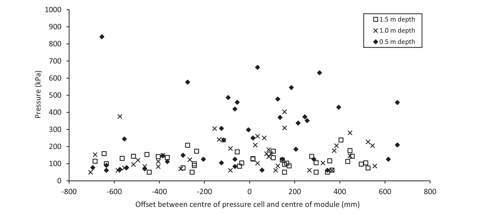
Fig. 5. Non-uniform pressure distribution measured at 0.5 m,1 m and 1.5 m depths.
Field Trial B was undertaken at Monarto Quarries during August 2014, albeit at a different location from Trial A. Natural soil was removed to a depth of 1.2 m, over a plan area 12 m long and 3 m wide. Three Geokon Model 3500 EPCs were placed at a constant depth of 0.8 m. Quarry fill material was placed in six equal lifts of 200 mm thickness,with each lift again being wheel-rolled using a Volvo L150E loader and a vibrating plate compactor used to compact soil within 200 mm from each EPC. The aim of the field trial was to measure the loading-induced stress at a single depth for 100 passes in total; 35 passes of the roller were conducted at a towing speed of 12 km/h prior to comparative EPC measurements being undertaken to achieve effective refusal. Five passes were conducted at each of the following towing speeds and in the following order: 12,10, 8, 6, 9, 7, 5,11,14,13 and 15 km/h, respectively. Due to time constraints, no EPC measurements were recorded between passes 90 and 100.
2.2.1. Material classification
The fill material placed for the trial was a crushed rock with a maximum particle size of 20 mm that was readily available on site.A summary of the particle size distribution(ASTM D6913-04(2009),2009) and standard (ASTM D698-12, 2012) and modified (ASTM D1557-12, 2012) Proctor compaction test results for Trial B is given in Table 1.The test results indicate that the material is similar to that used in Trial A;however,there are differences which can be attributed to the two-year interval between trials, different weather conditions at the time of testing, and the material being sourced from different parts of the quarry. For Trial B, the particle size distribution results are the average of seven tests, and the standard and modified Proctor compaction curves were generated using a minimum of five data points each; both laboratory compaction curves were generated five times. The field moisture content reported is the average of 30 tests undertaken.According to the USCS, the fill material is again classified as well-graded gravel(GW). Atterberg limit testing confirmed that the fines consisted of clay of low plasticity.
Density measurements and other in situ tests were not undertaken during either field trial presented in this paper.However,the authors carried out in situ test from pre- and post-compaction in very similar soil conditions as this study during a separate field trial that was also conducted at Monarto Quarries.The results have been published in Scott et al. (2016). It is acknowledged that only undertaking pre- and post-compaction testing provides limited information regarding changes in soil state with increasing compactive effort; however, such testing regimes are common as they are effective at determining whether a project specification has been met, or otherwise. A recently published paper by Scott et al. (2019) captured the ground response of a single module impact in real-time using buried EPCs and accelerometers.
2.2.2. Assessment of EPC results
Fig. 6 presents the minimum, maximum and average peak pressures that were recorded at varying towing speeds. As mentioned above,five passes were conducted at each target towing speed,with each pass traversing over three EPCs at a uniform depth of 0.8 m, resulting in 15 data points per towing speed. It can be observed that at towing speeds lower than 9 km/h, significantly lower pressure is imparted to the soil. The maximum pressure(1220 kPa) was recorded at a towing speed of 14 km/h and the highest average peak pressure (646 kPa) at a towing speed of 11 km/h. Large pressure variations were measured for the same towing speed due to limitations of using EPCs that are buried at fixed locations.The location of the centre of the module landing on the ground surface relative to the centre of a buried EPC is variable.As discussed by Avalle et al. (2009), this variability is something unable to be controlled(despite some attempts at trying to do so).As discussed by Scott et al.(2016),whilst the module is nominally a“square”, the sides have curved features,and this results in a nonuniform pressure distribution and is a key contributing factor why some passes yielded much larger peak pressures for the same towing speed than others.
Fig. 7 presents the same data set, plotted instead with peak pressure versus offset distance. Adjacent speeds have been combined to yield 30 data points for each line.It can be observed that,for increasing towing speed, greater pressure is imparted to the ground up to 11-12 km/h.For speeds of 13-14 km/h,the shape of the pressure versus offset relationship is in contrast to the other towing speeds,indicating that the corners of the module impart the greatest pressure. This suggests that the behaviour of the module changes with increasing towing speed,which is consistent with the findings of Clifford(1980)as discussed earlier.In contrast,at slower speeds,the module face produces the greatest impact.Fig.8 shows a plot of the peak pressure versus normalised time for the oddnumbered towing speeds. The largest peak pressure (1160 kPa)was recorded at a towing speed of 13 km/h.

Fig. 6. Minimum, maximum and average peak pressures for varying towing speeds.

Fig. 7. Large variation in peak pressure for varying offset distances and towing speeds.
To confirm the observations from the pressure cell data, a number of qualitative behaviours were observed; at lower towing speeds,the blows were delivered by the face of the module,which maintained a regular contact pattern with the ground. At faster speeds, the blows were delivered towards the corners, and the module was observed to skip along the surface from corner to corner,which is again consistent with the findings from Fig.7 and Clifford(1980).The spacing between successive blows of the roller module was also monitored and physically measured on site. The module imprint length was measured to be significantly larger than the physical face length (1450 mm) of the module for towing speeds greater than 13 km/h as indicated in Fig. 9, implying nonuniform rotation and skipping behaviour. Bradley et al. (2019)used high-speed photography that captured the kinematics of the 4-sided module at 1000 frames per second. The field work undertaken by Bradley et al.(2019)is highly relevant to the field work of this study even though the two field trials had different aims and motivations and were undertaken on separate(adjacent)test areas within the Monarto Quarries site. There are strong similarities between the two; both field trials were held concurrently, allowing the same 4-sided impact roller to be used and fill material from the same stockpile to be used. The study by Bradley et al. (2019)captured the motion and estimated the kinematic profile of the module during impact to estimate the energy imparted to the ground (23 kJ ± 4 kJ) for a constant towing speed of 10 km/h that was adopted during the trial.
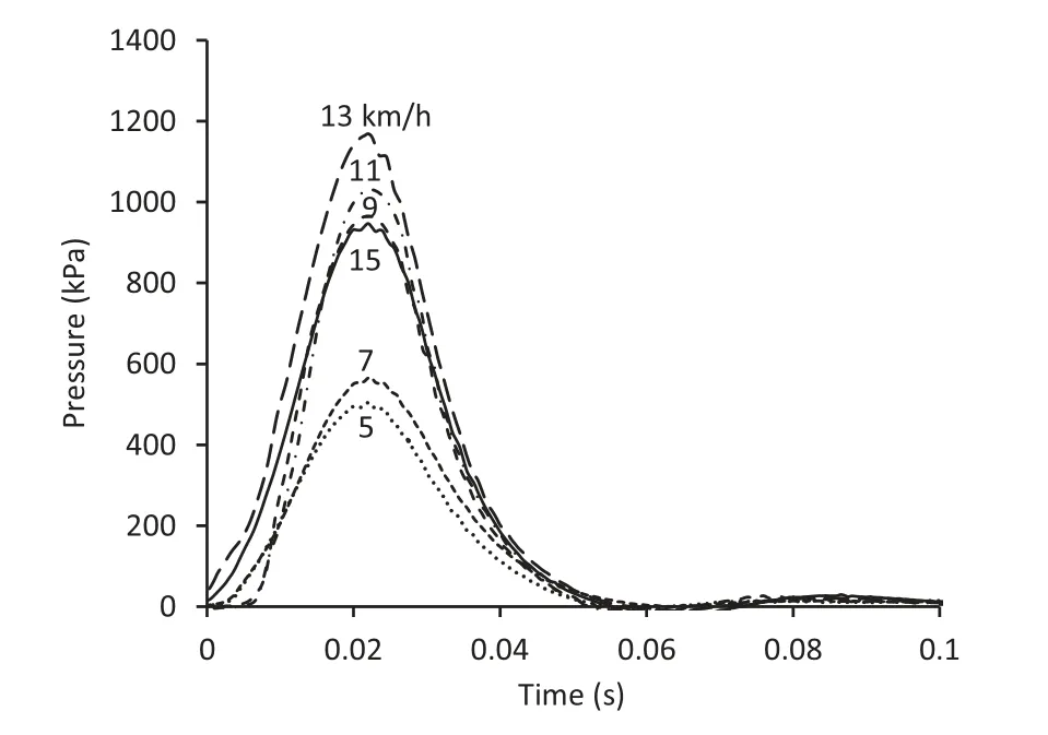
Fig. 8. Duration of pressure impulse not greatly influenced by towing speed.
3. Discussion
In this paper,towing speed refers to the horizontal motion of the towing unit, whereas rotational velocity refers to the angular velocity of the module. To quantify the difference between the two,Clifford and Bowes (1995) presented theoretical analyses from independent mathematicians who predicted the change in rotational velocity of the module as it falls to impact the ground.They claimed that towing speed was more significant than other factors such as module mass or lift height.Whilst the use of load cells is referenced in their paper, no experimental results were included to confirm their findings. Clifford and Bowes (1995) used high-speed photography to support their calculations regarding the change in angular velocity of the module during the lifting and falling phases of each impact for a constant towing speed. They explained that a key reason why the angular velocity of the module is not constant(unlike the towing speed) is due to the double-spring-linkage system on the 4-sided impact roller. Clifford and Bowes (1995)explained that the module velocity is slowed during the lifting phase as the springs of the double-linkage system are compressed.This causes the module to lag a little behind the towing frame that is travelling at a constant speed. During the impact phase, the springs are then discharged which cause the module to move faster than the towing frame as the spring energy is released. Whilst no results of the high-speed photography were presented in their paper,they claimed that the spring energy resulted in a decrease in rotational velocity during lifting,and an increase in module velocity during the falling phase.They found that the magnitude of change in module rotational velocity was inconsistent and was dependent upon soil surface irregularities.Their calculations proposed that the energy delivered by the 4-sided roller during a single impact can be described by kinetic energy,estimated to be up to 50 kJ,depending upon their assumptions made regarding the velocity of the module upon impact with the ground,vf.

Fig. 9. Inconsistent module imprint length on ground surface with increasing towing speed.
McCann (2015) used 3- and 5-sided modules and presented an alternative viewpoint, stating that the magnitude of the gravitational potential energy provides a reasonable estimate of the energy delivered by the 3-sided roller.McCann(2015)cited the work of Heyns (1998) who undertook both theoretical and empirical analyses.Heyns(1998)placed an accelerometer on the axle of a 3-sided impact roller to measure the magnitude of the peak deceleration of the module as it impacted the ground.Heyns(1998)used dynamic compaction theory from Mayne and Jones(1983)to infer the energy imparted to the ground based on the measured peak deceleration. Whilst good agreement between estimated and measured accelerations was noted by Heyns (1998), both are fundamentally based on dynamic compaction theory. The use of this theory without modification for RDC applications is questionable and requires further research. Heyns (1998), cited by Berry(2001), observed that an increase in towing speed resulted in an increase in energy imparted to the ground,but it was not the major component of the energy for towing speeds tested between 9 km/h and 14 km/h. After losses were taken into account, Heyns (1998)concluded that the magnitude of the gravitational potential energy, PEg(Eq. (1)), was a reasonable estimate for the energy delivered by the 3-sided roller to the ground. If this theory is applied to a 4-sided impact roller with a module mass, m, of 8-tonne and a maximum module drop height, h, of 0.15 m, the estimated energy imparted to the ground would be approximately 12 kJ.
PEg= mgh (1)
where g is the gravitational acceleration.
Clearly, there is a need for further research as this finding is in stark contrast with that of Clifford and Bowes(1995)who estimated the energy for a single impact using total kinetic energy, KE (Eq.(2)), based on an 8-tonne module mass, m, and a module landing velocity,vf,that was assumed to be greater than the towing speed.

The fact that Clifford and Bowes(1995)analysed a 4-sided roller and Heyns (1998) analysed a 3-sided roller may, to some extent,explains the disparity in results.The standard 4-sided impact roller,as shown in Fig. 1, consists of a single 8-tonne module that is 1300 mm wide,1450 mm high and rotates with the aid of a doublespring-linkage system. The standard 3-sided impact roller, as shown in Fig.10, consists of twin 6-tonne modules that are each 900 mm wide and 2170 mm high that rotate about a fixed axle with the aid of a hydraulic accumulator. The concept of energy storage upon lifting and release on impact theoretically increases the potential energy imparted to the ground; however, there is little, if any, published information that quantifies the magnitude of the energy that can be stored and released by either the double-springlinkage system or the hydraulic accumulator.

Fig.10. 3-sided RDC module (source: Landpac.com).
In an attempt to quantify the effects of the spring-linkage system, Clifford and Bowes (1995) analysed the change in angular velocity of the module before and after impact. They did not,however,quantify the contribution of spring energy in terms of the potential energy imparted to the ground. Whilst differences in impact roller configuration may account for some of the disparity in the estimates provided by Heyns (1998) and Clifford and Bowes(1995), there is clear disagreement as to whether the use of potential energy or kinetic energy provides more accurate estimates.It is also apparent that research is required to determine the effects of the double-spring-linkage system and the hydraulic accumulator to be able to accurately quantify the total potential energy delivered by the 4- and 3-sided impact rollers, respectively.
From both field trials undertaken, it is evident that the towing speed of the module influences the pressure imparted to the ground, suggesting that gravitational potential energy alone does not accurately capture the ground response of RDC. Whilst Heyns(1998) found that towing speed influenced the energy imparted to the ground at towing speeds higher than the typical range,these findings present compelling evidence that the magnitude of the energy imparted to the ground is a function of towing speed,even within the typical operating range of 9-12 km/h. Clifford and Bowes (1995) argued that module speed was a critical parameter,and that the continuous rolling action must be more beneficial than the equivalent falling weight that relied solely on gravitational potential energy. However, the magnitude of peak pressures measured in the ground with changes in towing speeds strongly suggests that the use of total kinetic energy does not accurately describe it either. If it did, greater changes in pressure would have been evident with varying speed. The observations indicate that total kinetic energy overestimates the contribution of towing speed, and therefore does not provide a reliable estimate of the energy imparted to the ground. Combining the findings of past research and the trials presented in this paper,the energy imparted to the ground appears to be a function of both potential and kinetic energies. To determine the magnitude of energy imparted to the ground by a single blow,it is necessary to analyse the potential and kinetic energy before and after impact in more detail, which is addressed below.
3.1. Energy imparted by RDC
considered a more appropriate means to describe the energy delivered by RDC, rather than relying solely on gravitational potential or total kinetic energy.
W = ΔPE+ΔKE (5)
The high-speed photography approach used by Clifford and Bowes (1995) quantified the spring energy in terms of a change in module rotational velocity as the springs are compressed and subsequently released. However, spring energy, as defined by Halliday et al. (1993), is a form of potential energy, therefore the contribution of the dual springs in the linkage system should,more appropriately, be quantified in terms of potential energy.
In order to estimate the energy imparted to the ground as a consequence of RDC, the conclusions from the high-speed photography undertaken by Clifford and Bowes (1995) are adopted. They indicated that, when compared to the average, the module velocity decreased by 10-20% during the lifting phase of the module,and increased by 10-20%during the falling phase.The module frame is towed at a relatively constant speed,therefore the speed of the module after impact with the ground is slower than that prior to impact, but is not zero as implied by Clifford and Bowes (1995) for their use of total kinetic energy to be correct.For calculation purposes,a module mass,m,has a velocity increase of +10% prior to impact, vi, and a velocity decrease of -10% after impact, vf, when compared to the average. These correspond to lower bound values stated by Clifford and Bowes (1995), to determine the work done due to the change in kinetic energy, Wke,which is equal to ΔKE, as defined using Eq. (3). The results are presented in Table 2.

3.2. Contribution of the spring-linkage system
The double-spring-linkage system consists of two springs: a large outer spring and a smaller inner spring that fits within the internal diameter of the larger spring. To determine the contribution of each of the springs to the energy imparted by the module,the stiffness of both springs was determined. Each spring was placed separately in a large compression machine whereby the load versus displacement response was quantified. The maximum compression of the dual springs was governed by the limiting compression distance of the outer spring,as both springs compress together in the towing frame.The force in the spring is determined using Hooke's law in Eq.(6),where the spring force,Fs,is a function of the spring stiffness, k, and the compression distance of the spring, x:
Fs= -kx (6)
Based on Halliday et al. (1993), the work done by a spring, Ws,can be determined by
The change in potential energy,ΔPEg,is equal to the work done due to gravity, Wg, therefore, the module falling to the ground surface can be described by Eq. (4), in which the module drop height after impact,h2,is equal to zero;hence for an 8-tonne mass,m, and a lift height (h1) of 0.15 m,ΔPEg≈12 kJ.
Wg= ΔPEg= mgh1-mgh2(4)
It should be emphasised that Eq. (4) gives the maximum potential energy that can be delivered to the ground.This energy will not be delivered with every impact as the full gravitational potential energy will only be reached when the module is compacting soil that is hard enough to allow the full lift height to be achieved.It is noted that using high-speed photography will also capture changes in module velocity due to the spring-linkage system, or due to energy losses in the system(such as frictional forces that act between the module and the ground surface). The net work done,W, as described by Eq. (5), is a combination of both the change in potential and kinetic energies, as work is being done against gravity, as well as inertia and frictional resistive forces, and is

where xmaxis the maximum spring compression.Using Eq.(7),it is possible to determine the work done, Ws, by both the inner and outer springs with varying spring compression distances up to the maximum (limiting) compression, xmax. Whilst having different spring stiffnesses,k,both the inner and outer springs compress by the same magnitude in the double-linkage mechanism, the work done by the springs is equal to the change in spring potential energy,ΔPEs, as described by
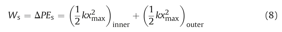
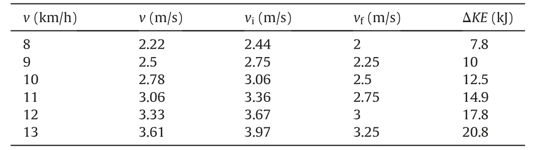
Table 2 Predicted change in kinetic energy based on high-speed photography by Clifford and Bowes (1995).
The outer spring was found to contribute 84%of the work done by the dual springs combined, due to the larger spring stiffness(k = 370 N/mm), compared to the inner spring (k = 70 N/mm).As observed in Fig.11,the work done by the springs is approximately 5 kJ at the maximum spring compression. This is the maximum energy that the springs are able to deliver, but the full potential energy of the springs will not be delivered with every blow,as both the geotechnical properties of the ground and the undulating surface profile significantly affect the behaviour of the module.

Fig.11. Energy contribution of the dual springs in the linkage system of the 4-sided impact roller.

Fig.12. Increasing energy for typical towing speeds of the 4-sided impact roller.
A summary of the work done with varying speed is presented in Fig. 12. It is observed that the change in gravitational and spring potential energies is constant for all speeds. The maximum spring energy is more likely to be realised at faster towing speeds; however, further research involving more direct measurement techniques is needed to confirm this.As stated previously,the change in kinetic energy,as quantified by Clifford and Bowes(1995),accounts for spring effects and this is supported by Fig.12,where ΔPEs<ΔKE.Without taking into account the spring energy contribution twice,the total work done is equal to the sum of the change in gravitational potential,and kinetic energies(Eq.(5)).This yields values of total work done between 22 kJ and 30 kJ for typical towing speeds of 9 km/h and 12 km/h, respectively. For the same speeds, Clifford and Bowes (1995) predicted 30 kJ-54 kJ, respectively, using Eq.(2) and assuming that the spring-linkage system increases the landing velocity of the module by 10%.The predicted energy that is imparted to the ground by Bradley et al. (2019) does support the assumptions made by Clifford and Bowes (1995) regarding the relationship between towing speed and module velocity that were used in this study to estimate the change in kinetic energy.Bradley et al.(2019)quantified the change in energy due to a single module impact from high-speed photography, and estimated that the energy imparted to the ground due to a single module impact was 23 kJ (±4 kJ) for a towing speed of 10 km/h, consistent with the findings of this study.
4. Conclusions
This paper examined the effect of towing speed on the energy imparted to the ground from the 4-sided impact roller. This involved combining theory from Halliday et al.(1993),observations from two full-scale field trials,high-speed photography by Clifford and Bowes(1995),and estimates of energy imparted to the ground for the 3-sided roller by Heyns (1998). The maximum imparted energy delivered to the ground by the 4-sided impact roller was found to lie in the range between 22 kJ and 30 kJ,for typical towing speeds of 9-12 km/h.
It is proposed that the energy imparted by RDC to the ground needs to be considered in terms of work done,which is due to the change in both potential and kinetic energies. Current practice of describing the energy imparted to the ground using total kinetic energy should be avoided as it overestimates the energy imparted to the ground. Describing the energy via the use of gravitational potential energy should also be avoided,but for a different reason;it is counter-productive for the impact rolling industry to develop specifications stipulating target towing speeds when the rollers are described solely in terms of their gravitational potential energy.
The change in potential energy is derived from a combination of both gravitational and spring energies for the 4-sided impact roller.The values presented in this paper for the potential energy delivered by the springs(5 kJ)and gravitational potential energy(12 kJ)are the maximum values that are theoretically possible. However,they are not values that will be achieved with every impact, as favourable ground conditions are needed for the full potential energy to be delivered. The change in kinetic energy is a function of the friction between the module and the ground surface. Quantifying the friction at the module-soil interface is extremely difficult to evaluate theoretically, as it depends on several variables associated with the module,such as the roughness of the module face in contact with the ground, the presence of wear plates or anti-skid bars, the contact area between the module and soil, and the towing speed. Properties relating to the ground are also significant,with soil type, grading, moisture content, density, elastic modulus and surface geometry all providing different frictional resistance,which makes it complex and extremely difficult to estimate the energy needed to overcome friction as it is material-dependent.
If the energy imparted to the ground was only due to potential energy,then it would be theoretically independent of towing speed and would be limited to a maximum value of 17 kJ.The findings of this research confirm that towing speed does influence the energy imparted to the ground.There is,therefore,a need for specifications to detail a target towing speed range for RDC.Based on the authors'experiences, the optimum speed will vary depending on site conditions. To optimise the use of the 4-sided impact roller, a towing speed range of 10-12 km/h is recommended, which is consistent with the findings of the field trials reported in this paper.
Declaration of Competing Interest
The authors wish to confirm that there are no known conflicts of interest associated with this publication and there has been no significant financial support for this work that could have influenced its outcome.
Acknowledgments
The authors wish to acknowledge the following civil engineering students from the University of Adelaide who contributed to the field work referred to in this paper: Andrew Bradley, Gianfranco Canala, Chris Gauro, Dapeng Liu, Jackson March, Chris Smith and Richard Strapps. The authors are grateful to the instrumentation and laboratory staff at the University of Adelaide who have provided invaluable assistance over the years and to Cathy Cates for her assistance with word processing. The authors are also grateful to Broons and Monarto Quarries personnel for access to equipment and the test site, without their help and support, the work undertaken in the field trials featured in this paper would not have been possible.
 Journal of Rock Mechanics and Geotechnical Engineering2020年1期
- Journal of Rock Mechanics and Geotechnical Engineering的其它文章
- On the use of 1g physical models for ground movements and soil-structure interaction problems
- Ground behaviour analysis, support system design and construction strategies in deep hard rock mining - Justified in Western Australian's mines
- Prediction of TBM jamming risk in squeezing grounds using Bayesian and artificial neural networks
- Multi-scale modelling of gas flow in nanoscale pore space with fractures
- Three-dimensional double-rough-walled modeling of fluid flow through self-affine shear fractures
- Numerical study on tensile failures of heterogeneous rocks