V2X-Communication Assisted Interference Minimization for Automotive Radars
Jingxuan Huang,Zesong Fei,*,Tianxiong Wang,Xinyi Wang,Fan Liu,Haijun Zhou,J.Andrew Zhang,Guohua Wei
1 School of Information and Electronics,Beijing Institute of Technology,Beijing 100081,China
2 State Key Laboratory of Wireless Mobile Communications,China Academy of Telecommunications Technology (CATT),Beijing 100083,China
3 Department of Electronic and Electrical Engineering,University College London,London WC1E 7JE,U.K.
4 University of Technology Sydney,Sydney,NSW 2007,Australia
Abstract: With the development of automated driving vehicles,more and more vehicles will be fitted with more than one automotive radars,and the radar mutual interference will become very significant.Vehicle to everything (V2X)communication is a potential way for coordinating automotive radars and reduce the mutual interference.In this paper,we analyze the positional relation of the two radars that interfere with each other,and evaluate the mutual interference for different types of automotive radars based on Poisson point process (PPP).We also propose a centralized framework and the corresponding algorithm,which relies on V2X communication systems to allocate the spectrum resources for automotive radars to minimize the interference.The minimum spectrum resources required for zero-interference are analyzed for different cases.Simulation results validate the analysis and show that the proposed framework can achieve near-zero-interference with the minimum spectrum resources.
Keywords: automotive radars; V2X communications; radar interference; spectrum allocation
I.INTRODUCTION
Automated driving vehicles (ADVs)are becoming a reality with the advancing of artificial intelligence and electronic technologies.Recently,advanced driver assistant systems (ADASs)have already been commercialized,while fully automated vehicles have been validated successfully in laboratory.By 2015,15% of vehicles were equipped with ADASs,while around 50-60% of vehicles are expected to have higher-level automation by 2020 [1].With the help of ADV,it is possible to prevent more than 85 percent of traffic accidents caused by human errors [2].Traffic jam will also be reduced by the coordination among ADVs.
Automotive radar is widely used in driver assisted systems to enable safety features such as adaptive cruise control and automatic emergency braking.Compared with camera and LIDAR,automotive radar is advantageous in that it can work at any time and under all weather conditions.On the other hand,vehicle to everything (V2X)communication is also a key component for ADVs [3].By connecting to the cloud and the fog using V2X systems,each individual vehicle can get global information,unlimited computing and storage resources and cooperation abilities.
Therefore it is favorable to have both sensing and communication capabilities equipped on the ADV,where the co-existing and the co-designed radar and communication systems are typically required [4].Some schemes were proposed to enable radar and communication systems sharing the same spectrum by eliminating the interference between these two systems [5]-[9],thus the frequency resources can be used more efficiently.The work in [5] proposed an opportunistic spectrum sharing scheme where the communication system utilizes the space and frequency spectra when they are not occupied by radar.The authors in [6] proposed a null-space projection method,in which radar signal is projected onto the null-space of the interference channels between the radar and the communication base station (BS).In [7],[8],the authors considered spectrum sharing between MIMO radar and multi-user MIMO (MU-MIMO)communications.The authors in [9] proposed an adaptive signal processing method for communication system to remove the interference from radar.
As a step further,some researchers focus on realizing radar and communication functionalities by use of shared waveforms [10]-[13].In [10],the authors proposed to exploit IEEE 802.11ad protocol for target detection.In [11],[12],sensing and communication systems were integrated on a C-RAN based mobile network.Recently,an MU-MIMO radar-communication waveform was designed to minimize the downlink multi-user interference while formulating a desired radar transmit beampattern [13].In [14],the authors investigated how to use radar signal for MIMO communication beam training.Nevertheless,it still remains an open issue that how the radar system can benefit from the communication systems.
The ADVs may be a suitable scenario that communication system can benefit to radar.With the increasing number of ADVs,the number of automotive radars will also increase.On the other hand,the spectrum resource for automotive radar is limited,thus enormous number of radars have to share the same spectrum,and significant radar interference will arise due to the lack of coordination among them.Particularly,interfering radars that are implemented in vehicles traveling in the opposite direction and work in the collision frequency band will create ghost targets that cause false alarm and noise-like interference which degrades the target detection performance [15],[16].The works in [17] and [18] suggested an approach that randomizes chirp sweeping frequency to reduce the false alarm probability.The authors in [19] modeled the automotive radar interference by using stochastic geometry,and proposed an optimization methodology to calculate the optimum random access probability that can reduce interference.In addition to the aforementioned techniques,V2X communication can introduce coordination between automotive radars and further reduce the interference,i.e.,bring gain for radars.
In this paper,we propose a new centralized framework that utilizes V2X communication system to allocate spectrum resources for the automotive radars and reduce interference.Similar to the conventional frequency division multiplexing (FDM)method,the frequency band is divided into several sub-bands.However,the number of sub-bands is limited,while the number of automotive radars is huge,it is impossible to allocate non-reused orthogonal band for each radar as mobile communication system.Thus in our proposed framework,the BS allocates the reused spectrum resources to minimize radar interference using a greedy algorithm based on the location and direction information of radars.We also analyze the positional relation of interfering radars,and evaluate the interference in different cases based on Poisson point process (PPP).Moreover,we analyze the minimum spectrum resources required for zero-interference.Simulation results show that our proposed framework can eliminate interference by using the minimum spectrum resources,while achieving higher radar detection probability compared with random spectrum access method when the spectrum resources are not sufficient.
The rest of this paper is organized as follows.In the second section,we formulate the model of radar interference.In the third section,we propose the spectrum allocation framework and the algorithm.In the fourth section,we analyze the average interference and the minimum spectrum resources required for completely avoiding interference.In the fifth section,we show the simulation results.At last we conclude the paper.
II.SYSTEM MODEL
In this section,we formulate the model of radar signal and radar interference.Then we construct the vehicle model that how radars are equipped on the vehicle.At last we present the positional relation of the two radars that interfere with each other.
2.1 Signal model and interference model
In practical scenarios,it is more likely for two radars to cause noise-like interference rather than ghost target [16],especially for frequency modulated continuous wave (FMCW)radars that are widely used in vehicles.Thus in this paper,we focus on noise-like interference,and utilize signal to interference plus noise ratio (SINR)to evaluate the performance of radar.
The power of the signal that is transmitted by the radar and reflected from the target can be characterized by the radar equation [20] as follows:

whereSis the received signal power,Ptis the transmitting power,Gtis the transmitter antenna gain,Ris the distance from the radar to the target,σcis the radar cross-section area (RCS)of the target,and is the effective aperture of the receiver antenna,whereGris the receiver antenna gain,andλis the wavelength.Note thatScan be equivalently divided into three parts as


where

represents the incident signal to the target,and

denotes the reflection from the target.Thus if the transmitted signal is received by an opposing radar that works in the same spectrum,the interference power will only depend onγtandAe,and the interference power from radarmto radarncan be expressed as

wherePtmandGtmare the transmitting power and transmitter antenna gain of radarm,respectively,Grnis the receiver antenna gain of radarn,andRmnis the distance between the two radars.
2.2 Vehicle model
Both automated driving vehicle and vehicle with ADASs could be fitted with more than one radar [21].There will be a long range radar (LRR)on the front of the vehicle for sensing distances of 10-250 m,enabling the features such as adaptive cruise control (ACC)and brake assist.There will also be several medium range radars (MRRs)and short range radars (SRRs)on the front,side or the back of the vehicle for sensing distances of 1-100 m and 0.15-30 m,respectively.The MRRs/SRRs on the front and side are for collision warning,cross traffic alert and blind spot detection,while the MRRs/SRRs on the back mainly provide backup parking assist [22].
Since the radars on the back are mainly used for parking,the interference generated to the vehicles can be neglected in general.We therefore only consider radars on the front and the side.In this paper,we assume that each vehicle is fitted with three radars,i.e.,one front radar,and two side radars on the left and right respectively.Each vehicle is equipped with V2X systems that work in the different frequency bands with the automotive radars.For simplicity,we assume each radar shares the same parameters,and denote the transmit power asPt,the antenna gain asG,and the antenna beam width asθ.Note that the three radars in the same car have different direction,thus the interference among them is negligible,and can be eliminated by self-cancellation.
2.3 The geometrical layout of radar interference
A geometrical layout of interfering automotive radars is illustrated in figure 1,which shows the potential interference between two opposite radars on the road.In figure 1,we decompose the distance into two directions,one is the extension direction of roads,denoted as ±z,and the other is the vertical direction,denoted as ±L,thus the location of a vehicle can be expressed as (z,L).The interested vehicle located on the zero point is called the typical vehicle,and the driving direction of the typical vehicle is +z.
First we will investigate the interference to the front radar of the typical vehicle.The front radar will be interfered by other front radars of the vehicles traveling in the opposite direction.Consider the antenna beam width and ignore sidelobes,the interfering front radars are mounted on the vehicle beyond a minimum distance,as shown in figure 1 (a).The location of the interfering front radar satisfies
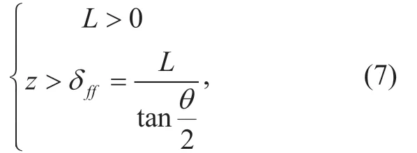
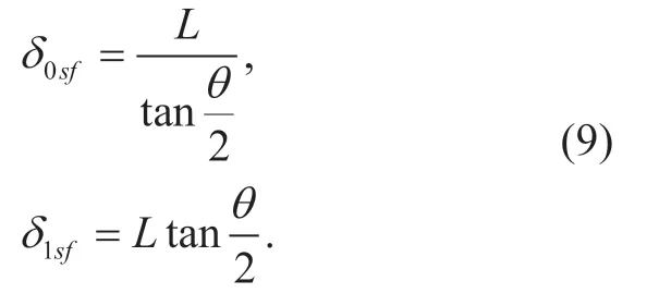
whereδ ffis the minimum distance.Ifthe front radar of the typical vehicle will also receive the interference from the side radars of the vehicles that locate between a minimum distanceδ0sfand a maximum distanceδ1sfon the other lanes,as shown in figure 1 (b).Specifically,the location of the interfering side radar satisfies

where
Similarly,the side radar will be interfered by other opposite side radars equipped on the vehicles of other lanes,as shown in figure 1 (c).For example,for the left side radar of the typical vehicle,the location of the interfering side radar satisfies

wheres


where
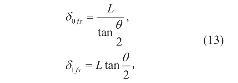
as shown in figure 1 (d).
From the discussion above,we observe that the most significant interference is generated from one side radar to another.If the antenna beam width is narrow,the interference between a side radar and a front radar will disappear,and the interference between two front radars is small because the distance is quite large.However,it is always possible that two opposite side radars are closer to each other.
III.THE PROPOSED INTERFERENCE MINIMIZATION FRAMEWORK AND ALGORITHM
In this section,we introduce the framework that utilizes V2X communication network to allocate spectrum resources and minimize automotive radar interference.We formulate an optimization problem,which is then solved via a greedy algorithm.
3.1 V2X Communication assisted radar spectrum resource allocation framework
It is impossible to allocate non-reused orthogonal spectrum resources allocation for automotive radars.Typical automotive radar,e.g.,FMCW radar,requires a large bandwidth of at least 200 MHz [26].Even though there is totally 2 GHz bandwidth for automotive radars at 77 GHz in most countries [16],only 10 non-reused orthogonal sub-bands can be used.Considering the huge amount of automotive radars,especially for dense traffic situation,it is meaningful to study how to allocate the limited resource based on location information to minimize the interference.
In the proposed framework,the vehicles in a section of road belong to the same base station.For vehiclej,denoting the index of its front radar,left side radar and right side radar as 32j- ,31j- and 3j,respectively,we have

whereMis the total number of automotive radars andJis the total number of vehicles.The frequency band of automotive radar is divided intoTorthogonal sub-bands with the same bandwidth.Denote the sub-bands allocation matrix asF∈{0,1}MT×,and denote themth row ofFasfm.We havefm∈{0,1}1×T,wherefm(t)1= means the th sub-band is allocated to radarm.
Each vehicle uploads its parameters to the base station,including the locations and the orientations for each radar.The base station can also require speed information to predict the location of vehicles during two uploading slots.After that,the base station calculates the potential interference between the automotive radars.The potential interference means there is interference if two radars were allocated with the same sub-band.Location,radar orientations and antenna beam widths are substituted to Eq.(7-12)to decide whether there exists potential interference between two radars.If two radars interfere with each other,the base station further calculates the distance between these two radars,and then gets a potential interference matrixP∈RMM×based on Eq.(6),where

is the potential interference from radarmto radarn.Note thatPis a symmetric matrix,and main diagonal elements are zero.The base station needs to allocate sub-bands for radars to minimize the total interference.The optimization problem is given as follows:
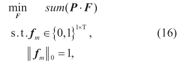
3.2 Interference minimization algorithm
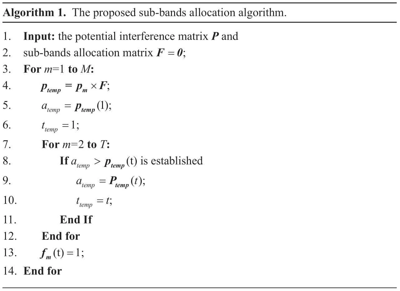
Here we propose a greedy algorithm to solve the minimization problem.First the sub-bands allocation matrix is initialized as a zero matrix.Then the base station allocates the sub-bands for radars in the order of their index.For each radar,the base station calculates the interference that will be introduced to all sub-bands,and allocates the radar with the sub-band that the introduced interference is minimum.The detailed algorithm can be found in Algorithm 1,wherepmis themth row ofP.
IV.THEORETICAL ANALYSIS OF RADAR INTERFERENCE
In this section,we analyze the mean power of radar interference by using PPP.Moreover,we analyze the minimum number of sub-bands required for zero-interference.
4.1 Radar interference mean
Without loss of generality,we consider the two-lane road with two opposing traffic directions.For a certain lane,we assume there is no correlation between the locations of vehicles,and all vehicles are located in the centerline of the road.Under this assumption,the locations of vehicles resemble a unidimensional PPP in R1with a homogeneous linear intensityρ[23].For a typical vehicle,the interference to its front radar and left radar comes from the vehicles in the other lane.We denote the set of vehicles in the other lane as Φ.Without the proposed framework,each radar accesses one ofTorthogonal sub-bands randomly,thus the probability that two opposing radar access the same sub-band and interfere with each other is 1/T.We apply random thinning on the vehicles set Φ with a retention probabilityξ=1/T.An illustration of the proposed road model is shown in figure 2.
Utilizing the result in Subsection 2.3 we can get the expressions of interferer set.For the front radar of the typical vehicle,the interferer front radars set can be expressed as

where Μff(z) is a random mark defined as

andB(ξ) is a Bernoulli random variable with selection probabilityξ.For the interferer left radars set Θsf,the random mark Μsf(z) can be expressed as

Similarly for the left radar of the typical car,the random mark for the interferer front radars set Θfsis

Algorithm 1.The proposed sub-bands allocation algorithm.1.Input: the potential interference matrix P and 2.sub-bands allocation matrixF 0= ;3.For m=1 to M:4.p = p Ftemp m× ;5.atemp =ptemp(1);6.ttemp =1;7.For m=2 to T:8.If atemp >ptemp(t)is established 9.a t temp =Ptemp();10.t t temp = ;11.End If 12.End for 13.fm(t)1= ;14.End for
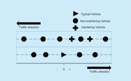
Fig.2.The illustration of the proposed road model.
The random mark for the interferer left radars set Θssis

For the typical vehicle at the zero point,the distance to another vehicle in the next lane can be expressed as

where L1is the lane width.Neglecting the length and width of the vehicle,Eq.can also express the distance between two radars,and the power of interference can be expressed as

Fig.3.Full-interference set of the straight road.
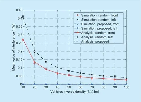
Fig.4.The interference mean versus vehicle linear intensity.

where

Thus for the front radar of the typical car,the aggregated interferencePfcan be written as

By applying Campbell theorem [24] to Eq.,we can calculate the mean value ofPf:

In the worst case thatθ≈180°,i.e.,the antennas have a very low directivity,we havethus

Similarly,for the left radar of the typical car,the aggregated interferencePscan be written as

And the mean value ofPsis

In a worst case thatθ≈180°,we haveδ0fs=0 andδ1fs=δss=∞,and

Note that while we only consider the simple scenario of a two-lane road,it is straightforward to extend the analysis to the multiple-lane situation.
4.2 Minimum number of sub-bands required for zero-interference
Denote Γ as a set of radars,where every radar in Γ has potential interference with all reminded radars,i.e.,the corresponding rows and columns in the potential interference matrixPconstitute a sub-matrix,where every elements are nonzero except the main diagonal elements.We named Γ as a full-interference set.Note that in Γ,we have to allocate different orthogonal sub-bands for different radars,otherwise there is interference among the radars in this set.Thus the minimum number of required sub-bands equals to the maximal size of Γ.Denote the minimum number of required sub-bands asN,we have

Generally speaking,Nis decided by the locations and the orientations of the vehicles.In figure 3 we observe the full-interference set of the straight road for the worst case whenθ≈180°.From figure 3 we can find that for the straight road,we haveN=2 if there are two lanes of opposing traffic directions,andN=4 if there are four lanes.
V.SIMULATION RESULTS
In this section,we present the simulation results for the averaged radar interference and radar ranging success probability,and compare the performance of our proposed sub-bands allocation framework (proposed framework)with the random access scheme (random scheme).The vehicles are deployed over a length of 1000 m in front of the typical vehicle,and over a length of 1000 m behind the typical vehicle.We consider the worst case whenθ≈180°.The other simulation parameters can be found in Table I.
In figure 4,we present the average interference versus vehicle linear intensity for the two-lane road.We setT=2,andρvaries from 0.01 to 0.1.The average interference for both the front radar and the left radar of the typical vehicle is presented.From figure 4,first we can see the simulation results match well with the analysis for the random scheme.We can also find that the average interference decreases with the decreasing of vehicles intensity,and the average interference for the left radar is larger than that for the front radar.In addition,for the proposed framework,the simulated average interference for the front radar and the left radar of the typical vehicle is zero,which validates that the proposed framework can reduce interference significantly.

Table I.Simulation parameters.

Fig.5.The average interference versus the number of sub-bands for two-lane road.

Fig.6.The average interference versus the number of sub-bands for four-lane road.
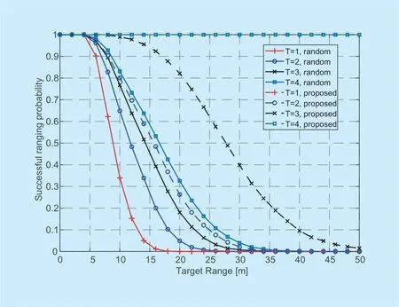
Fig.7.The radar ranging success probability versus the target distance.
Figure 5 and figure 6 show the average interference versus the number of sub-bands for both two-lane road and four-lane road.The average interference of the front radar and the left radar of the typical vehicle and the normalization total interference for all radars on the road are presented.We setρ=0.1,and varyTfrom 1 to 6.In both figure 5 and figure 6,whenT=1,the average interference is the same for the proposed framework and the random scheme.However,with the increase ofT,the average interference in the proposed framework decreases much faster than the random scheme.The normalization total interference decreases to zero whenT≥2 in figure 5 and whenT≥4 in figure 6,which means the proposed framework can achieve zero-interference for all radars with the minimum required number of sub-bands,for both two-lane situation and four-lane situation.
In figure 7,we show the radar ranging success probability versus the ranging distance for the left radar of the typical vehicle when the number of lanes is four.We setρ=0.01,and varyTfrom 1 to 4.
Successful ranging and detection require that the SINR is larger than a certain thresholdTh.For dense traffic conditions,interference limits the performance rather than noise,thus in simulation we calculate the signal to interference ratio (SIR)and count the number of times that it exceeds the threshold to obtain the simulated success probability.From figure 7 we can find that for the random scheme,the improvement of the success probability is not obvious withTincreasing.Moreover,the success probability for the random scheme is lower than 0.9 when the target is more than 10 meters away,and this probability approaches zero when the target range is 30 m.However,the success probability improves notably whenTincreases by using the proposed framework.WhenT=3,the success probability decreases much slower with target range increasing.And whenT≥4,there is no interference between radars,thus the success probability is only limited by noise.This result gives further insight that the electromagnetic compatibility (EMC)design of the automotive radar may be relaxed with the help of communication systems,e.g.,the transmitting power can be increased to improve the detection performance.
VI.CONCLUSIONS
In this paper,we proposed a framework that utilizes communication system to allocate orthogonal frequency sub-bands and minimize the automotive radar interference.A greedy algorithm was proposed to resolve the minimization problem based on the location and the parameters of radars.The Poisson point process was used to formulate interfering radars and to calculate the average interference.Moreover,the minimum number of orthogonal frequency sub-bands was also analyzed.The simulation results verified the analytical results,and demonstrated the effectiveness of the proposed framework.It was also validated that the proposed framework could use the minimum number of sub-bands to eliminate interference.
ACKNOWLEDGEMENTS
This work was support by China Information Communication Technologies Group Corporation.This work was also supported in part by Chinese Ministry of Education-China Mobile Communication Corporation Research Fund under Grant MCM20170101,and the European Union's Horizon 2020 research and innovation programme under the Marie Skłodowska-Curie Grant Agreement No.793345.
- China Communications的其它文章
- A Satellite Communication System Transmission Scheme Based on Probabilistic Shaping
- Application of Neural Network in Fault Location of Optical Transport Network
- Distributed Optimal Control for Traffic Networks with Fog Computing
- A Real Plug-and-Play Fog: Implementation of Service Placement in Wireless Multimedia Networks
- New Identity Based Proxy Re-Encryption Scheme from Lattices
- A Sensing Layer Network Resource Allocation Model Based on Trusted Groups

