Routing Loop Audit Mechanism Based on SDN
Tao Yu*,Yuchen Zhang,Diyue Chen,Hongyan Cui,*,Jilong Wang
1 Institute of Network Science and Cyberspace,Tsinghua University,100084
2 State Key Laboratory of Network and Switching Technology,Beijing University of Posts and Telecommunications,Beijing 100876,China
Abstract: Routing loops can cause packet loss and long delay problems in the traditional network.Even in future networks - Software-Defined Networks,with loop-free implementation mechanism,it still suffers loop problems.In this paper,we propose an architecture to solve the loop problem in SDN.Unlike the existing passive routing loop detection algorithm,this algorithm processes based on the SDN loop-free characteristic,by auditing third-party network forwarding rules’ modification requests to avoids loop generation,thus avoid the network loop problems.Testbed is built to simulate our proposed algorithm.The evaluation shows that the loop audit algorithm proposed in this paper has better performance in extra spatial utilization and smaller number of extra interactions between SDN controller and switches.
Keywords: software-defined network; Open-Flow; routing loops; forwarding request
I.INTRODUCTION
SDN is increasingly used in the data center [1],for SDN-based data center architecture makes the network forwarding capacity perform better,as well as lower network control complexity and energy consumption [2][3].In addition,the development and deployment of service level agreements (SLAs) based on SDN is also simplified [4].In order to achieve higher network capacity [5],plenty of “richly-connected” data center network architectures have been proposed to replace the traditional tree architecture,such as Fat-Tree [6],BCube [7],FiConn [8],uFix [9],etc.These architectures employ abundant switches and links to enjoy full bisection bandwidth at traffic peak time.Although these rich network structures guarantee the high capacity of the network,the structure of the network becomes very complex,too many redundant links make the network prone to the issues of routing loops,routing black holes and others.
In many implementation of SDN controller,such as floodlight,OpenDaylight,Ryu,etc,these controllers are born to be loop-free.First,controllers have global topology information of the network,the routing strategy is the shortest path first (DFS) or Dijkstra algorithm.These algorithms are all loop-free,so no loop would be generated from the calculated routing.Second,the matching field of the flow entry is directly filled by obtaining data packet header,so as to realize the accurate match of the data stream.So,according to the two loopfree reason mentioned above,one flow entry computed by the controller routing algorithm will not affect uncorrelated data streams.Therefore,the implementation strategy makes SDN a loop-free network.
But research shows that even if in SDN,loop problems still exist.Papers [15,16,17,19] discussed about the network update consistency problem issued by the SDN strategy may lead to temporary loops in the network.Paper [11] also discussed the implementation of Loop-Free Alternates (LFAs) algorithm as fast reroute algorithm for OpenFlow-based SDN may leads to loops in the network,and they came up using header filed as ID encoding to detect loops.In paper [20],a mechanism called SIMPLE,a SDN-based policy enforcement layer for efficient middlebox-specific “traffic steering”,is presented,but SIMPLE may cause routing loops in the networks.Therefore,the solution of routing loop in the SDN is also discussed in papers.The paper [13] studies the detection of routing loops using package headers and TTL value,and this method is user in the paper [12] to find loops caused by node failure in flow-aware multi-topology adaptive routing.
Besides the reasons mentioned above,the network forwarding modification request from outside controller (e.g.REST API) can also cause SDN routing loop.According to the paper [10],20% network errors are caused by the incorrect network maintenance,especially in the SDN architecture,which provides the ability to operate the network flow entry for application layer.This flexibility also brings new risk,and may also generate routing loops in SDN,even if it is loop-free in the implementation mechanism.Third-party business requests like the operation and maintenance department and the security department modified forwarding strategy for their special needs may affects the forwarding behavior of the unrelated data stream for lacking of global forwarding views or matching multiple data flows with a wide match field or high priority,resulting in routing loops or black holes.
In this paper,we audit the forwarding rule modification request from the outside controller:
1.Would the third-party routing forwarding rule modification request affect the forwarding behavior of unrelated data flows and lead to routing loops.
2.Would the higher priority flow entry already exists on the switching affect the forwarding behaviors of the third-party request flows and result in the routing loops.
We propose an audit mechanism aiming at forwarding rules requests that may lead to routing loops.When designing the loop avoidance mechanism,we take the advantage of the loop-free characteristics in SDN to avoid useless calculations.Compared with traditional routing loops detection methods applied on SDN,and global flow table synchronization loop detection method,our mechanism has a good optimize at the complexity of the algorithm storage space,or the complexity of controller-switch interaction numbers.In our simulation,the calculation time of a switch with 8000 flow entries takes about 800ms.
The remainder of the paper is structured as follows.Section II discusses loop detecting solution in traditional networks and SDN.Section III explains how to check forwarding rules modifications request to avoid loop in SDN based on OpenFlow protocol.Section IV introduces the complexity of the audit mechanism algorithm proposed in this paper,and compares with the existing solutions,as well as presents simulation results.Section V summarizes our research and outlines our future work.
II.RELATED RESEARCH
The method of detecting loops in SDN network is difficult to complete on the switches because the switch function is limited and the switch do not run as the distributed routing protocol.With the routing function transferred to the controller,controller obtains the running status of the whole network and the routing information of each switch.By analyzing flow tables of each switch,loops in the network can be detected.However,due to the complexity and diversity of the business data flows,the number of routes on a single node and the routing strategy is very large.It will take a huge calculation time and storage to traverse the whole network node and the routing strategy to find loops,which will be a huge burden for controller.At present,the detecting strategy for SDN routing loops can be divided into the following categories
In paper [11],the author proposes an automatic rerouting mechanism for SDN,which is realized by implementing LFAs algorithm in SDN.However,in some cases,to prevent node failures or multiple failures,LFAs can cause loops,making additional links unusable.The author proposed a scheme to deal with the loop generated by LFAs.In his algorithm,a special fields of the header part (e.g.DSCP,ECN,MPLS of the IP header Field) will be used to identify switch IDs,and an additional flow entry is added to each switch to detect loop flows.When switches output flows with its ID token and receive flows with the same token,this flow is detected to be loop flows and will be discarded by flow table action.The algorithm is implemented by assigning a single token between 1 and N for each switch.N is the total number of switches in the network.In the traffic sent by the switch,theith- bit of the header field indicates whether the traffic has passed through the switchi,and if the same flow pass through a same switch twice,a loop is detected.This loop detection just helps to prevent loops for LFAs,but it cannot protect traffic for which no LFAs exist.Although it is not designed for all flows,the idea of add tags in flows is widely used in traditional network and we will make comparison later.In addition,the usage of tag to solve the routing loop has also been applied in other papers.In the paper [20],the design of the scenario does not use VLAN and Tos field,so the implementation of the mechanism takes VLAN and Tos field as the label of flows.
In paper [13],a routing loop detection method is proposed through detecting replica streams of the network.If a loop occurs in the network,the same flows are repeated on the switch in the loop until the packet escapes from the loop or the TTL reduces to zero.The switch reveals these replica packets have the following characteristics:The headers of the packets are the same,but their TTL values are decremented and the TTL values differ by at least 2.If a replica stream is detected,the algorithm consolidates the flows through the switch into a loop to determine the location of the loop.When there are multiple loops in the network,by integrating those overlapping data flows in time,these flows are likely to be generated by the same routing loop.In paper [12],this method of packet header matching and TTL value comparison is also used to detect routing loops due to link failures and node failures in Flow-Aware Multi-Topology Adaptive Routing.
The method proposed in this paper has the following shortcomings:In order to achieve the algorithm,the router needs to cache all the packet headers information it forwards for a period of time and TTL field,to make comparison.The calculation of the algorithm is huge,thus will influence the performance of the router.If the cached package match filed and TTL value are in switch tables,which means almost one loop detecting flow entry for one forwarding route,flow tables usage will be reduced to about 50%.
In patent [14],authors proposed a routing loop detection method based on SDN,with SDN centralized control architecture,the controller obtains the global topology and flow table information to build flows forwarding map to determine whether a routing loop exists.This mechanism maintains a global flow table information and realizes real-time synchronization of network flow.To save the time interaction complexity,paper [21] proposed a weak vertex cover algorithm to synchronize global flow tables.
This method has the following shortcomings:1.With the network size becoming larger and the size of the flow table on switches increasing,the maintenance of the entire network flow table information consumes large storage resources.2.With the network size becoming larger,the update of the routing table is frequent and the amount of interaction between switch and controller is too large.
In addition to routing loops detection,there are many papers studying network update consistency problems,which lead to routing loops in SDN.Due to the inconsistency of the flow table update,some switch flow table update early,and others update late,thus leads to temporary routing loop during update gaps.In paper [15],in order to solve the problem of inconsistency update in flow table,the author proposed a “per-packet consistency” flow table update method,which means a packet is forwarded along the path of either strategy one or two,instead of a mix of them to avoid inconsistency.Paper [16] comes up with a strategy flow table updates improved by paper [15],and it points out that paper [15] method is too strong for forwarding loop free property.They show that a careful ‘mix’ of the old rule and new rule could hold forwarding-loop free property.This method constructed a dependency tree based on the forwarding path.After building up the dependency tree,update schedule is arranged as:starting update process from the root and then updating children of each node in sequence [18].
III.SYSTEM DESIGN
3.1 System analysis
In OpenFlow protocol,the calculation of the route is obtained by running the routing algorithm on the controller instead of being decided by the switch,and SDN controller maintains the global network topology.The shortest path first algorithm is loop-free algorithm and the matching field of the flow entry is automatically generated to achieve accurate match.Therefore,the flow entries calculated by controller’ SPF algorithm will not bring loops to the network and the flow entry will not affect unrelated flows.
However,in switches,the flow entries not only come from routing algorithm,but also a flow table modification API provided by the controller to the third-party (such as the operation and maintenance,security department,etc.) to operate switch flow entry for application layer‘s special needs.So these APIs break SDN loop-free properties,we need to check forwarding rules modifications request from API to avoid loops.
In order to provide an audit function for a third-party forwarding rule modification request,we proposed a concept called Virtual Routing,which is preceded by simulating the request impact on the network before request is sent to the associated switch.If the simulation results show the request will generate a routing loop in the network,Virtual Routing will logically reject the request and provide the appropriate information,otherwise the request flow entry will be sent to the switch.In the next section,we will show how Virtual Routing demonstrate routing loop audit process.
3.2 Virtual routing design
To prevent the flow forwarding request from resulting in routing loop,Virtual Routing needs to simulate routing paths in the following two scenarios:
1.Will a third-party routing forwarding rule request affect the forwarding behavior of unrelated data flows and result in routing loops?
2.Will higher priority flow entry rules already exist on the switch modify the forwarding behavior of the third-party request related flows,leading to routing loops?
In general,before the third-party traffic forwarding rule request takes effect,it is necessary to determine whether there are unrelated flows on the new switch being affected or higher priority existed flow entries affecting the third-party forwarding request to cause loop.
To make readers understand the loop audit strategy,we provide two examples to show how the Virtual Routing works.
1) Scenario One
Unrelated flows are affected by third-party routing forwarding rule requests and result in loop,which can be shown in the following example:
The original traffic forwarding path in the network is →S1→S2→S3→ as indicated by the green arrow,at this point network received a manual third-party routing forwarding request to carry a new flow →S2→S3→S4→S1→,as indicated by the dashed red arrows,the forwarding request and original flow comes to a meet atS2.When SDN controller receives the third party request,the request will be sent to relevant SDN switches,S2,S3,S4,S1.If the matching field of the flow table can match the data flow of the green arrow (as shown in figure 1.),the forwarding behavior of the existing flow is modified:
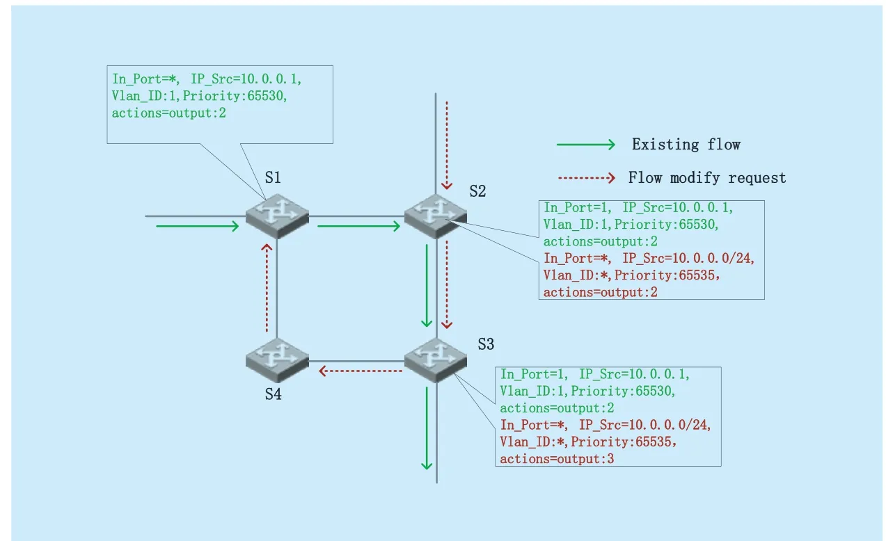
Fig.1.Loop generate in scenario one.
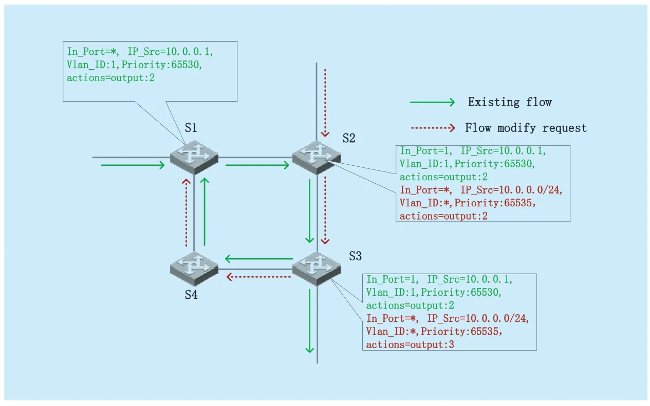
Fig.2.Loop forwarding routes in scenario one.
The forwarding behavior of the data flow will be changed after the modification of the green arrow of forwarding rules request comes.When forwarding the flow to the destination nodeS1according to the request,if there is an associated flow entry onS1,it can process flows coming after the request,as shown in figure 1.,AfterS1receiving the flow,it will go as the way ofS1→S2,and then captured by the modification request inS2,then formed a loop,as shown in figure 2.
Of course,under normal circumstances,when a flow entry with correct source IP address,destination IP address,TCP port and MAC address,VLAN ID,etc.,it will not match to other data flows,but the third party request is manually set and the matching field may be not accurate,for example,the source IP segment is too broad,VLAN ID is not set,the incoming port of the flow is not set,or the priority of the set flow entry is too high,thus affect the destination unrelated flow forwarding strategy results in the emergence of routing loops.In fact,each matching field in the actual environment is more complicated,but if the matching field is provided by application layer or third parties,the forwarding behavior of the unrelated flows cannot be avoided of matching problem.
When unrelated flows mismatch,the Virtual Routing mechanism will simulate the effect of the third-party request on the existing traffic forwarding behavior in the network before the request is mapped to switches.The steps of the simulating algorithm are as follows.
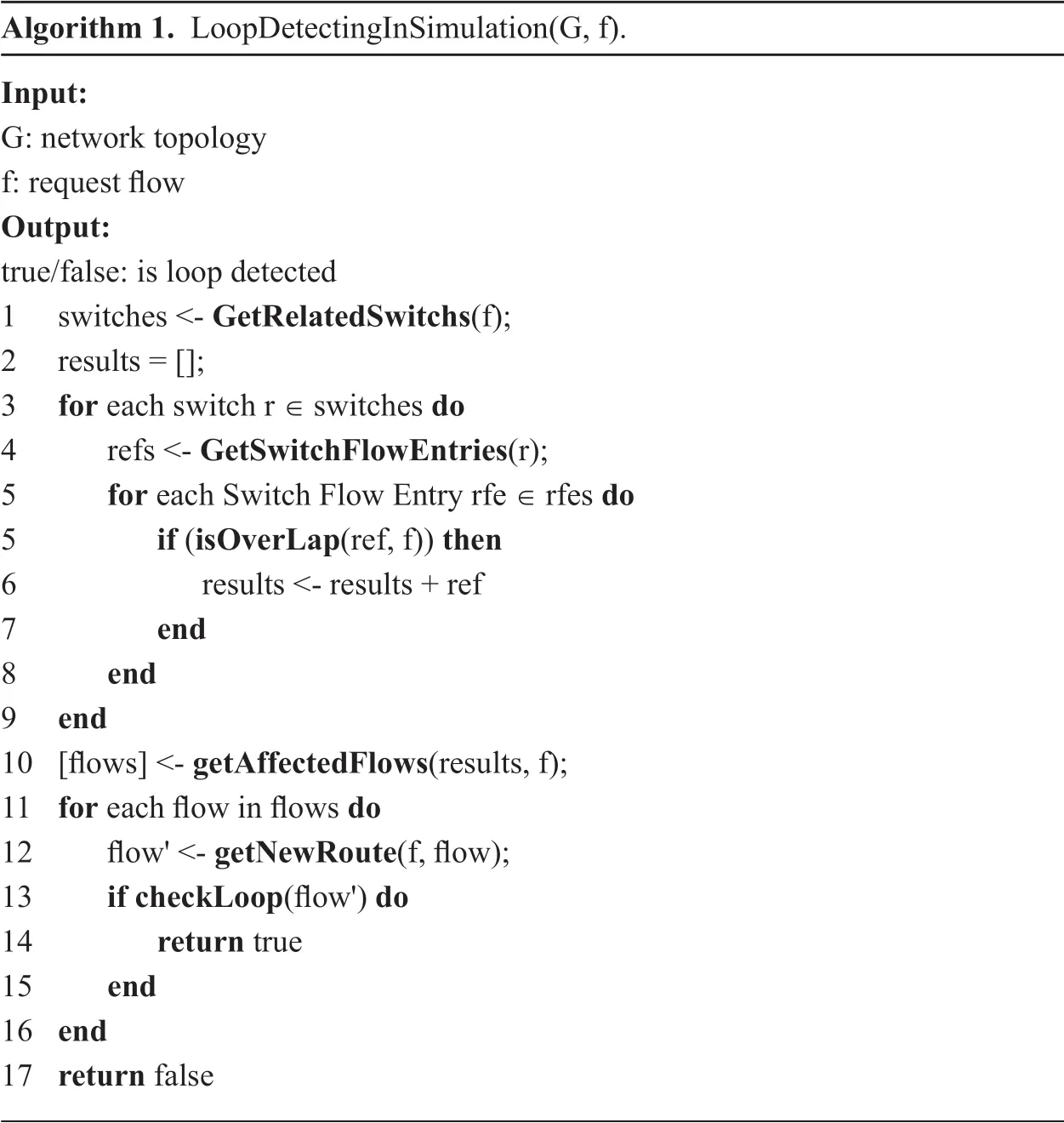
In our algorithm,when it comes a forwarding modification requestsf,our algorithm will get all the switches involved inf,for each flow entry on every switch inf,we check overlaps between flow entry andfto find out flows will be mismatched byf,then calculate the forwarding strategy of the mismatched flows and use loop algorithm to detect whether there is loop generation.The whole process goes as algorithm 1.
In the algorithm,isOverlapfunction will return the overlapped flows,getAffectedFlowsfunction will check the priority,and return flow entries whose priority is smaller than the priority of the requestf.These flow entries are affected data flows.
If an unrelated data flow is detected to be affected by request,the new forwarding behavior will be simulated by thegetNewRoutefunction.
After the new forwarding behavior of the affected data flow is obtained,the loop algorithm can calculate whether there is a routing loop in the forwarding behavior.In the loop detectioncheckLoop,for saving the space occupied by the algorithm,we only use two pointers to traverse the route and find loop in the route.One pointer is called fast,the other pointer is called slow.The two pointers come from the beginning of the route to traverse,and fast pointer once moved two steps,while slow pointer move one step once,if loop exists in the route,the fast pointer and the slow pointer will meet in the end,otherwise end the algorithm.
With the process above,we can find out whether flows affected by forwarding modification request will end up with loops.
2) Scenario Two
Higher priority flow entry already exists on the switch modifies the forwarding behavior of the third-party request-related data flow,resulting in a routing loop.This scenario can be shown in the following example:
As is shown in figure 3.,if the third-party forwarding rule modification request is →S2→S3→ in the red arrow,but there is a higher priority flow entry inS3as indicated in the green arrow,this flow entry can match the request flow due to matching priority and header field set,so flow comes followed by the request will change its forwarding behavior affected by existing flow entry.
When requests lead the flow coming,it will be forwarded followed by the rules of the higher priority flow entry.The forwarding behavior in the real network is shown in figure 4.
Algorithm 1.LoopDetectingInSimulation(G,f).Input:G:network topology f:request flow Output:true/false:is loop detected 1 switches <- GetRelatedSwitchs(f);2 results = [];3 for each switch r ∈ switches do 4 refs <- GetSwitchFlowEntries(r);5 for each Switch Flow Entry rfe ∈ rfes do 5 if (isOverLap(ref,f)) then 6 results <- results + ref 7 end 8 end 9 end 10 [flows] <- getAffectedFlows(results,f);11 for each flow in flows do 12 flow' <- getNewRoute(f,flow);13 if checkLoop(flow') do 14 return true 15 end 16 end 17 return false
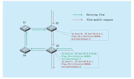
Fig.3.Loop generate in scenario two.
As what can be seen from the figure,since the forwarding behavior is modified by the higher priority flow entry,the request’s flow generates a routing loop in the network,thus affects the performance of the related switches.In this case,if the existing flow entry matching field is broad enough to affect request data,we also need to use Virtual Routing to simulate.The algorithm goes as follows:
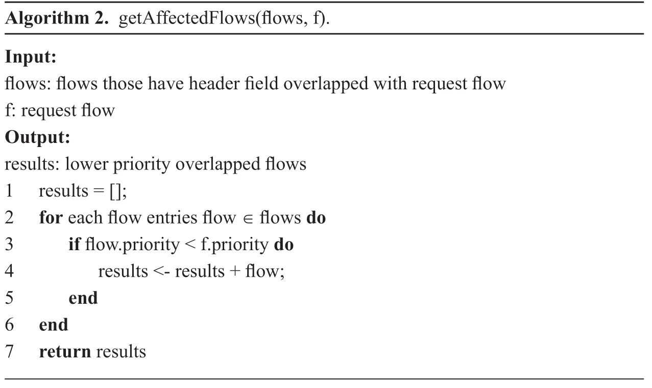
Algorithm 2.getAffectedFlows(flows,f).Input:flows:flows those have header field overlapped with request flow f:request flow Output:results:lower priority overlapped flows 1 results = [];2 for each flow entries flow ∈ flows do 3 if flow.priority < f.priority do 4 results <- results + flow;5 end 6 end 7 return results
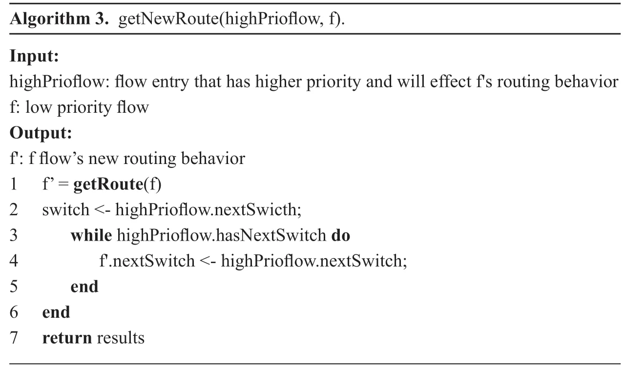
Algorithm 3.getNewRoute(highPrioflow,f).Input:highPrioflow:flow entry that has higher priority and will effect f's routing behavior f:low priority flow Output:f':f flow’s new routing behavior 1 f’ = getRoute(f)2 switch <- highPrioflow.nextSwicth;3 while highPrioflow.hasNextSwitch do 4 f'.nextSwitch <- highPrioflow.nextSwitch;5 end 6 end 7 return results
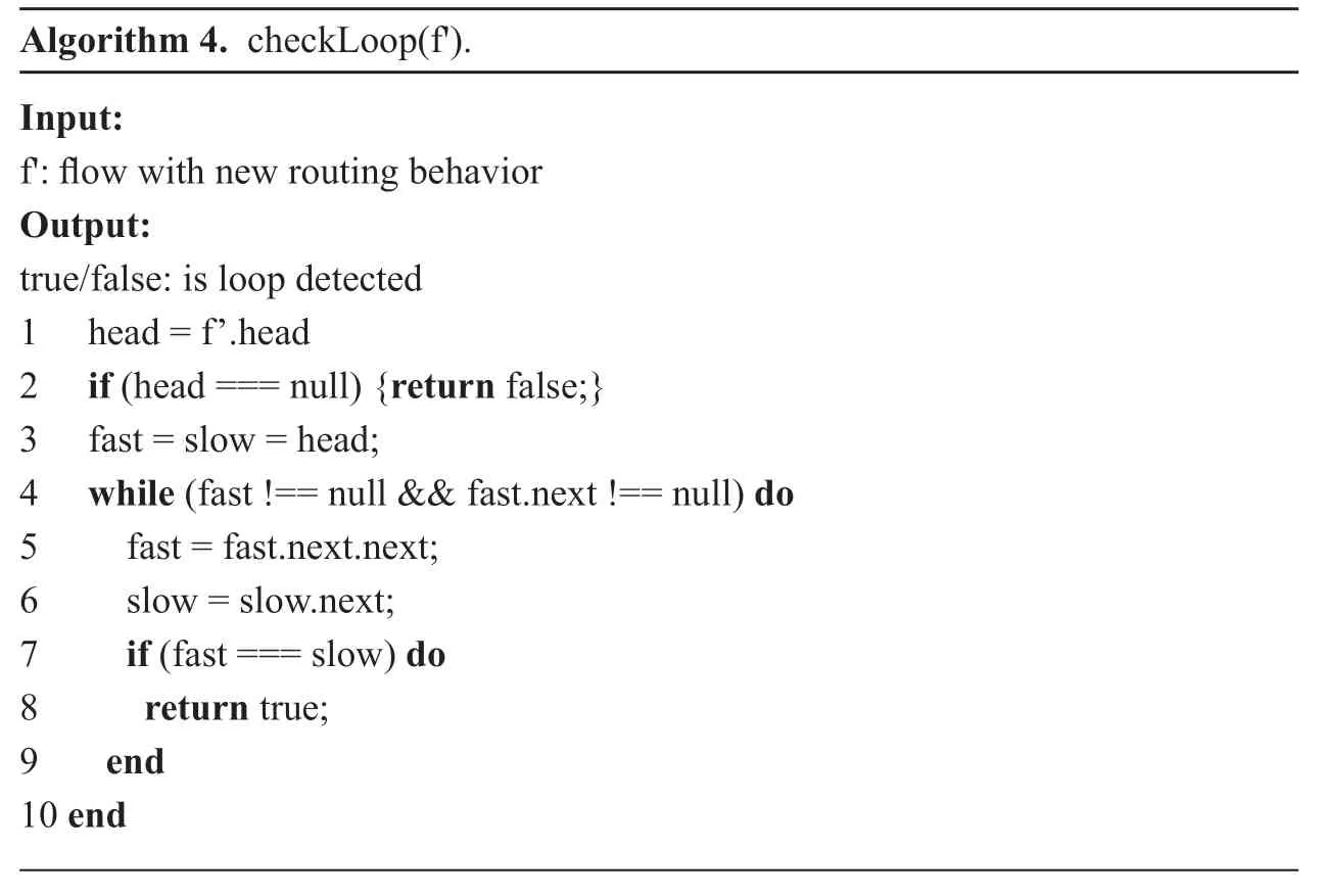
Algorithm 4.checkLoop(f').Input:f':flow with new routing behavior Output:true/false:is loop detected 1 head = f’.head 2 if (head === null) {return false;}3 fast = slow = head;4 while (fast !== null && fast.next !== null) do 5 fast = fast.next.next;6 slow = slow.next;7 if (fast === slow) do 8 return true;9 end 10 end
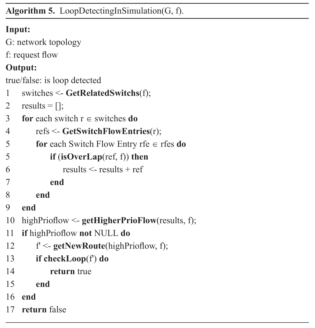
In this process,most steps are the same with scenario one,but the biggest difference between it and the first case is that in this situation,existing flow entry has a higher priority than the request flow entry priority.So in this case,we find the first stream entry that request’s data will match.getHigherPrioFlowfunction achieves this goal.
What’s more,the return value of thegetHigherPrioFlowfunction should be the first parameter of thegetNewRoute.
3) The Time Complexity of the Algorithm
Taking common fat-tree datacenter network topology as an example.The time complexity of the routing loop audit algorithm is related to the number of switches in the route and the number of flow entries in the switch.In the route,there are up to five switches in the fattree network,so the complexity of the switch being through isO(1).In this algorithm,we need to traverse all the flow entries of the switch involved in the request,so the time complexity of the algorithm is only linearly related to flow entry number in the switch,On(),wherenmeans the flow entry number in the switch.
IV.EVALUATION
4.1 Implementation and experiments
To find out the exact time utilization of this scheme,we implement the routing loop audit method as a module of floodlight,and do the network simulation in Mininet.Because the algorithm complexity proposed in this paper is related to the number of flow entries in the switch,we adjust the frequency of the traffic requests initiated by hosts in the network to create flow entries.In the simulation,we use Mininet 2.3.0 with 4-port switches’ fat-tree topology as the simulator,totally 20 host,16 switches composed in the object.Then we use Python script to automatically run the test,including initialization of switches and network,connecting Floodlight controller,and use Iperf to generate random UDP data flows in one virtual machine with the configuration of CPU i7-6700,4G memory and 20G disk.The size of the data flow is 1Mbit,and the duration of the data flow is randomly distributed from 1 to 30 seconds,the source and destination host are randomly selected.
In simulation,by controlling the probability of each host,we start UDP traffic to control the number of flow entries on switches.For each probability we simulate 20 times,then collect each experiment time of detecting the network loops.The experiment results are shown in figure 6 and Table.1.
In the simulation,by setting the probability host sending new UDP request,we simulate the network random flow event,running the loop calculation algorithm.We also get algorithm calculation time in Table.1.The result shows that as the number of flow entries grows,the algorithmic computation is growing,as we can see in figure 6,where the time is spent.
Figure 6 shows the relationship between probability of host that sends UDP traffic and the average flow entry number in the network.And the bar in figure 6 shows the relationship between the simulation algorithm processes time and the number of flow entries in the switch.We can see that Virtual Routing simulation time depends on two parts,the first part is the controller gets flow entries information form switches,the second part is traversed flow entries consumption time.According to the figure,the traversing time increases when the number of flow entries,and the time of collecting flow table information from the switch is related to the network status.In order to better show the relationship between time consumption and the number of flow items,we add more flow entries to the network and get figure 7.
From figure 7 we can see that the flow traversal time and the number of flow entries are positively correlated,and the average traversal time of 5000 flow entries is about 400ms,which depends on server hardware configurations.In addition,the transmission time of the flow entry data in actual environment is more than the simulation environment and the server is faster than the simulation environment in the actual network,so the total time consumption of the algorithm will depend on a greater extent on the transmission time.
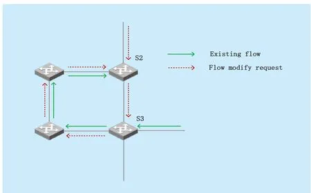
Fig.4.Loop forwarding routes in scenario two.
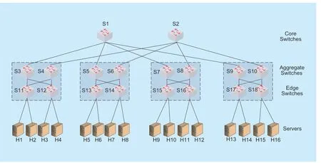
Fig.5.Fat-tree network topology structure.
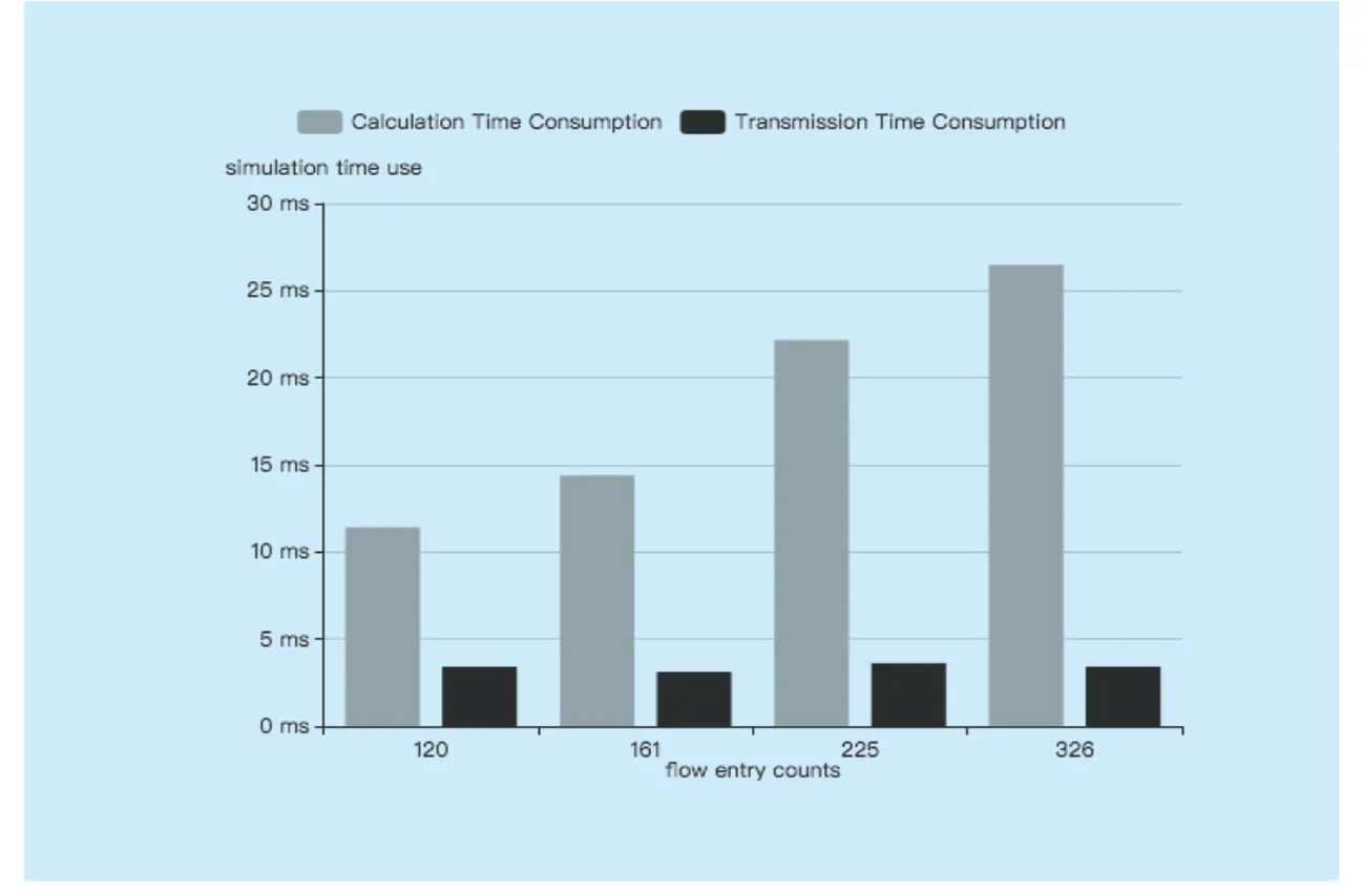
Fig.6.Time consumption against flow entry counts.
Algorithm 5.LoopDetectingInSimulation(G,f).Input:G:network topology f:request flow Output:true/false:is loop detected 1 switches <- GetRelatedSwitchs(f);2 results = [];3 for each switch r ∈ switches do 4 refs <- GetSwitchFlowEntries(r);5 for each Switch Flow Entry rfe ∈ rfes do 5 if (isOverLap(ref,f)) then 6 results <- results + ref 7 end 8 end 9 end 10 highPrioflow <- getHigherPrioFlow(results,f);11 if highPrioflow not NULL do 12 f' <- getNewRoute(highPrioflow,f);13 if checkLoop(f') do 14 return true 15 end 16 end 17 return false
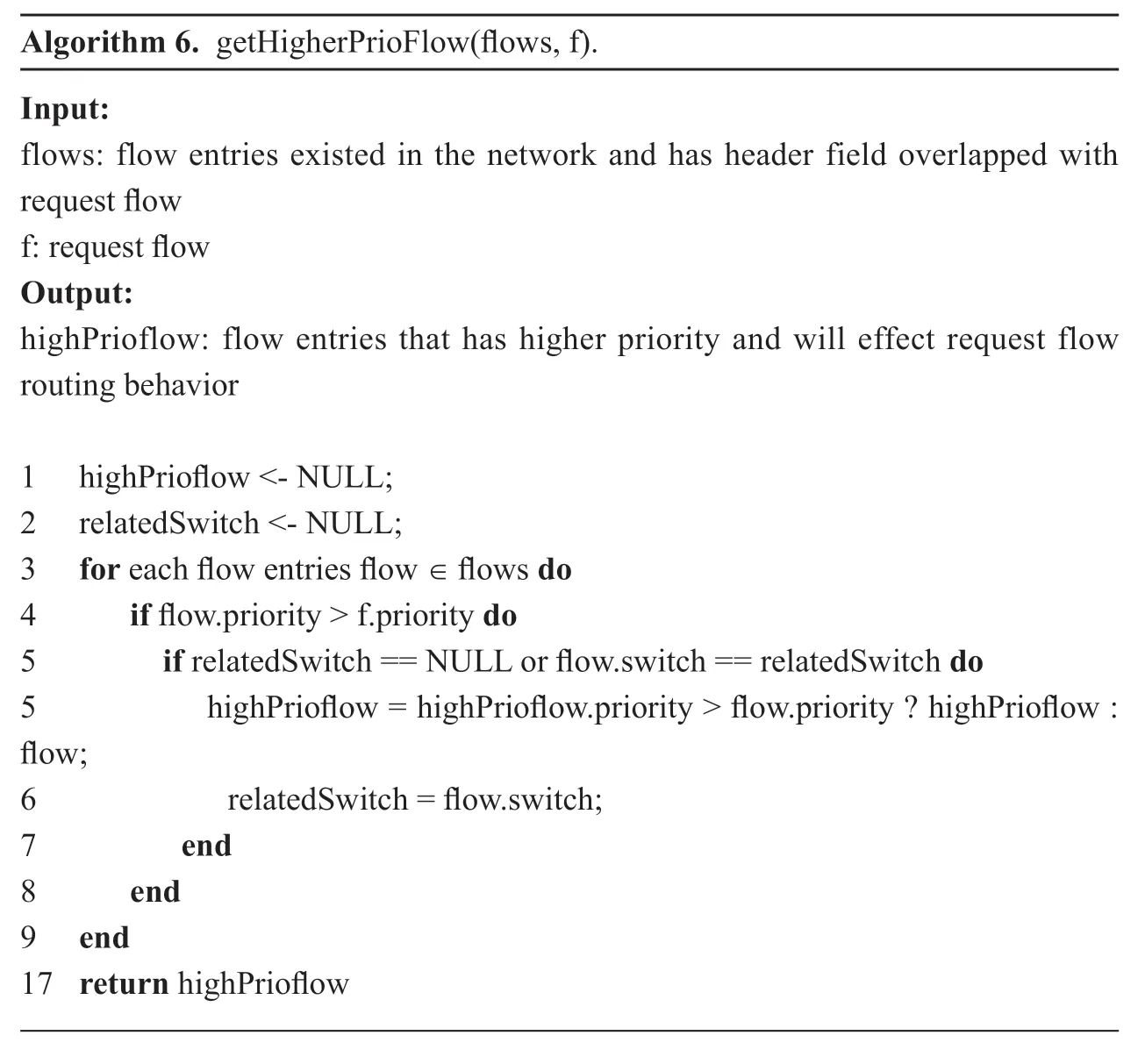
Algorithm 6.getHigherPrioFlow(flows,f).Input:flows:flow entries existed in the network and has header field overlapped with request flow f:request flow Output:highPrioflow:flow entries that has higher priority and will effect request flow routing behavior 1 highPrioflow <- NULL;2 relatedSwitch <- NULL;3 for each flow entries flow ∈ flows do 4 if flow.priority > f.priority do 5 if relatedSwitch == NULL or flow.switch == relatedSwitch do 5 highPrioflow = highPrioflow.priority > flow.priority ? highPrioflow :flow;6 relatedSwitch = flow.switch;7 end 8 end 9 end 17 return highPrioflow
Figure 8 shows the relationship between transmission time and flow entry counts.
In figure 8,we can get that when the flow entry counts is small (<1000),the time required for the controller to obtain the switch flow table information is almost Not affected by the number of flow table counts,but the key factors are server IO time,network delay and so on.When the number of flow entries is more than 1000,the time to obtain the data with the number of flow table items increases,roughly linearly.Thus,we can get the following optimization points:
When the number of flow entry counts is small,the time of controller obtains the flow table information mainly depends on the system IO time and the network delay,so it’s better to combine small batches of flow meter information into a single time period to obtain a large number,thus saving additional IO time and network delay consumption.In the SYNC-Loop algorithm,whenever a change in the flow entry on the switch,the synchronization of the flow table entry is performed and wastes a lot of time on IO and network delay.But our algorithm only triggers when a third party request comes,and gets all the flow tables from the switch in one network session,savings network resources.
4.2 Comparison of similar algorithms
Compared with this algorithm are similar routing loops strategy:1.Using flow table tags for routing loop detection algorithm,abbreviated as:Header-Tag.2.Identify the same flow header and compare the TTL,abbreviated as:TTL-Loop.3.Synchronize the network state and use the topology loop detection,abbreviated as:SYNC-Loop.The indicators of comparison are:the time complexity of the algorithm,the extra space used by the algorithm,the number of extra interactions between the switches and the controller.
Let’s analyze the complexity of the algorithm.Assume that there aremswitches in the network andnflow entries on each switch.
1) Header-Tag algorithm,
This algorithm draws on the idea of the paper [11] and paper [20] that loop is detected by matching the incoming traffic tag of the flow.Flow tag is set when flows come out of the switch and then it is detected when returns to the switch.In paper [11],this schema is used for detecting FLA protected flows,if this method is used for detecting each flow,it is likely that the length of the tag field is insufficient due to too many switches in the network.Therefore,to overcome it,other matching field such as flow IP,MAC address,port,etc.should be set to match each flow,leading to use multiple loop detecting flow entries in switches.As the loop detection flow table is a sequential match,the algorithm has a time complexity ofO(n).The extra space used by the algorithm isO(n),which is not on external storage but on switch flow table.When implementing this algorithm,the controller needs to send an extra flow entry to the switch per flow,so the number of additional controller interactions isOmn(*).
2) TTL-Loop Algorithm
According to paper [13],Loop detecting is on the switch,which caches flow headers and TTL values when sending out flow,and match each flow header when flow comes.So the algorithm’s time complexity isO(n)for matching each flow.The extra spatial complexity isO(n).For the fact that the algorithm is implemented in a non-SDN network and therefore does not have interactions with the controller.If is not in SDN,the header can be cached automatically by the switch,so the extra interaction will also be 0.But if the header and TTL value are cached in flow forwarding table as presented in paper [12],the extra interaction will beOmn( *).
3) SYNC-Loop Algorithm
The idea of this algorithm is to synchronize flow table information of all the switches in the network to construct the forwarding map,and run the loop detecting algorithm.The time complexity of the algorithm isO(n).Because all the flow tables of all the switches are to be stored,the spatial complexity of the algorithm isOmn( *),and the controller needs to synchronize flow table information.So the flow entry overtime needs to be synchronized to the controller,the number of additional interactions to the controller should beOmn( *).The paper [21] proposes a method to cover weak vertex.The best time and spatial complexity isO(n)while the worst isOmn( *).

Table I.Simulation time.
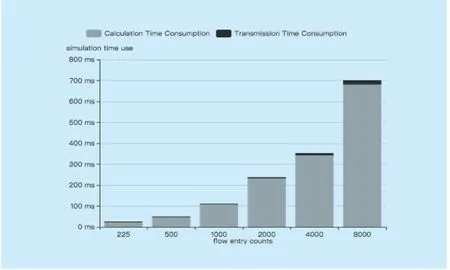
Fig.7.Time consumption against flow entry counts.
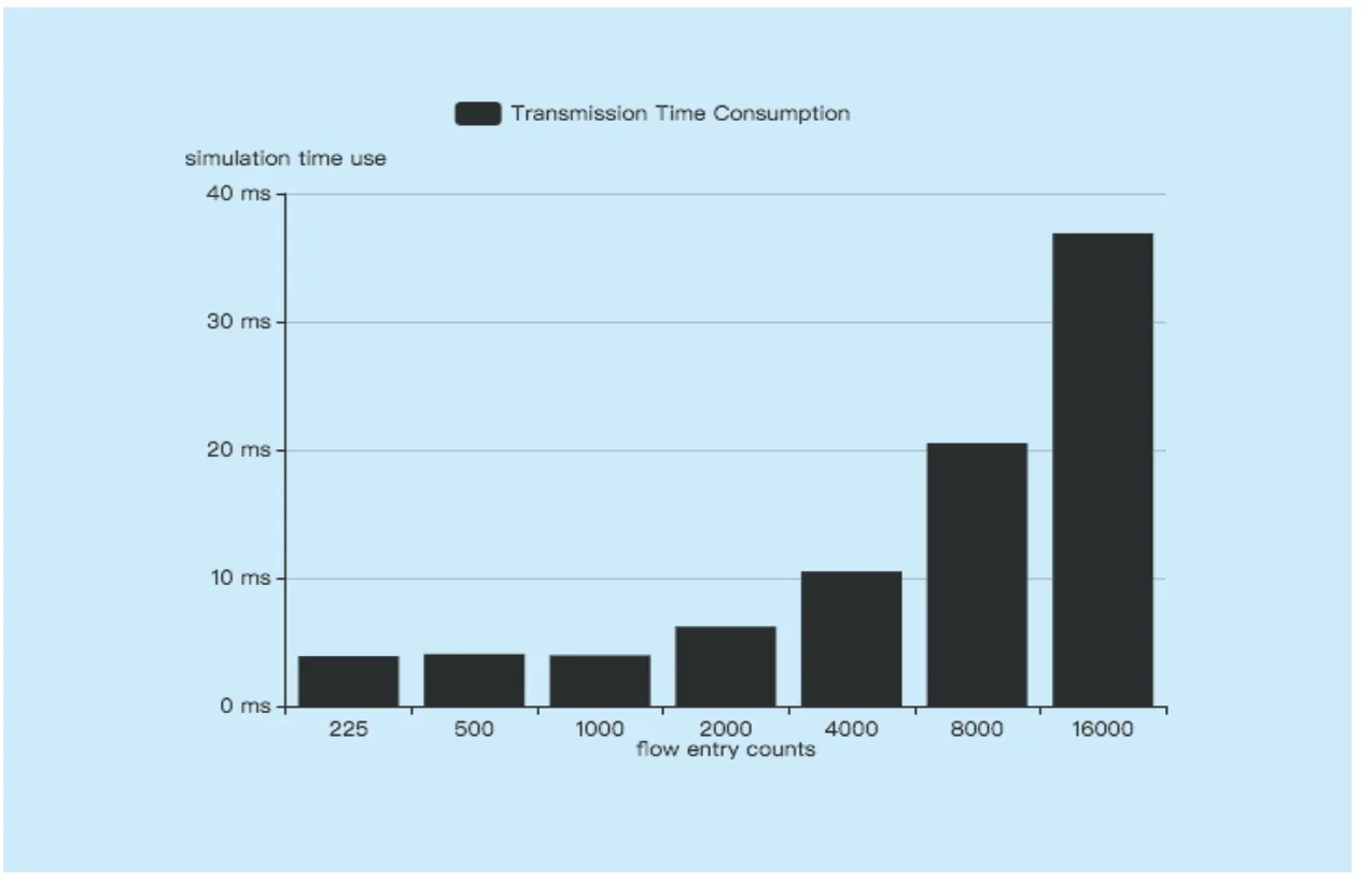
Fig.8.Transmission time consumption against flow entry counts.
4) Virtual Routing Algorithm
Our algorithm needs to traverse all the flow tables on the request-related switches.Therefore,the time complexity of the algorithm isO(n).Before traversing,it needs to store the flow table information of the related switch,where the spatial complexity isO(n).The number of switch interacts with the controller depends on the number of related switches,so the number of additional interactions isO(1).
So,we can get a comparison table shown as Table.2.,wherenis the number of flow entries on the switch,mis the switch number.
If the network has fat-tree topology,there arenswitches in the network,and the number of flow entries per switch isO(n2),the algorithm comparison table is shown as Table.3.
But not every algorithm is suitable for SDN.If implemented in SDN,the Header-Tag algorithm and TTL-Loop algorithm using flow forward table as implemented in paper [12] have the same time and spatial complexity.Besides,additional interactions are controller sending extra flow entries to detect loops each switch.However,this method needs to create an extra matching flow entry for each flow entry in the switch.Therefore,only 50% of the flow table space in the switch is available,and the other half is used for loop detection.Open-Flow switches store their flow tables in expensive,limited TCAM.Since the stored tablescannot be large,this method costs too much and is not suitable in SDN implementation.The TTL-loop algorithm needs to cache the header information and TTL value of the output flows for a period of time.By comparing the packet header of the received flows and TTL value,it can detect the loops.The advantage is that header information can be stored outside the flow table to save the switch’s flow table space.But this loop detecting process is on the switch,which goes against SDN concept of separated controlling and forwarding ability.Besides,when traffic in the network increases,traversing through cached headers consumes a lot of time,such problem might affect the forwarding performance of the switch,which is unbearable in switches.

Table II.Comparison of similar algorithm.

Table III.Comparison of similar algorithm.
For the third method,it will synchronize all the flow entries of the switch to be backed up on the controller,and when the switch flow entry deletes,it is necessary to notify the controller to delete the backup flow entry.The advantage of this method is that we do not need to use extra flow table space and this method matches the concept of SDN.However,synchronous switch flow entry will take up a lot of interaction resources,in the case of more switches,it will bring a lot of burden to the controller,so this method is suitable for the network with less switches.
The scheme of this paper makes use of the loop-free characteristic of SDN,so it is a targeted loop avoidance strategy for the third party forwarding rule modification request which may cause loop in SDN.Since the calculation of the loop detecting is done on the controller,no extra flow entry is required.It only needs to synchronize the flow table information of the request related switches,and each switch requires one extra interaction,so the complexity of extra interactions should beO(1).
V.SUMMARY
In this paper,we propose an audit algorithm for the case that the third-party network forwarding rule modification request may cause loop in SDN.In this algorithm,we use the loop-free characteristics of SDN to audit the request for forwarding rules.Compared with the traditional network used in header matching with TTL value or matching field with switch ID tag,this method saves the extra flow table space and reduce extra calculation on switch to ensure forwarding performance.Compared with the method of synchronizing switch flow entries,this method has less number of interactions between the controller and switches as well as extra spatial complexity.
ACKNOWLEDGEMENT
This work was supported by the project of Ministry of science and technology special emphasis Research and Development Surveying and Mapping Cyberspace Resources (NO.112044017001),Cernet Next Generation Internet Technology Innovation(No.NGII20170417),and China Ministry of Education - CMCC Research Fund (No.MCM20170306).
- China Communications的其它文章
- Research on Mobile Internet Mobile Agent System Dynamic Trust Model for Cloud Computing
- EEG Source Localization Using Spatio-Temporal Neural Network
- DDoS Attack Detection Scheme Based on Entropy and PSO-BP Neural Network in SDN
- Constructing Certificateless Encryption with Keyword Search against Outside and Inside Keyword Guessing Attacks
- Customizing Service Path Based on Polymorphic Routing Model in Future Networks
- Energy-Efficient Joint Caching and Transcoding for HTTP Adaptive Streaming in 5G Networks with Mobile Edge Computing

