Decoupled Delay and Bandwidth Centralized Queue-Based QoS Scheme in OpenFlow Networks
Weihong Wu ,Jiang Liu *,Tao Huang
1 State Key Laboratory of Networking and Switching Technology,Beijing University of Posts and Telecommunications,Beijing 100876,China
2 Beijing Laboratory of Advanced Information Networks,Beijing 100876,China
3 Beijing Advanced Innovation Center for Future Internet Technology,Beijing 100124,China
Abstract: There are an increasing of scenarios that require the independent bandwidth and delay demands.For instance,in a data center,the interactive message would not occupy much bandwidth,but it requires the rigorous demands for the delay.However,the existing QoS approaches are mainly bandwidth based,which are inappropriate for these scenarios.Hence,we propose the decoupled scheme in the OpenFlow networks to provide the centralized differential bandwidth and delay control.We leverage the mature HTB to manage the bandwidth.And we design the Queue Delay Management Scheme (QDMS) for queuing delay arrangement,as well as the Comprehensive Parameters based Dijkstra Route algorithm (CPDR) for the propagation delay control.The evaluation results verify the decoupling effectiveness.And the decoupled scheme can reduce the delay for high priority flows.
Keywords: software-defined networks; openflow; quality of service; decoupled delay and rate
I.INTRODUCTION
QUALITY of Service (QoS) is essential for t he current networks.Different services have diversified flow characteristics.Thus,they require different network performance to provide the eligible QoE (Quality of Experience).The QoS mechanisms contain the IntServ and the DiffServ[2].The IntServ can provide the QoS commonly by reserving the network resource for the service.While in DiffServ,the services can be classified into several QoS categories,each of them corresponding to different QoS configuration.The typical IP network leverages a classic method called DSCP[3] (Differentiated Services Code Point) for the QoS,which assigns the TOS (Type of Service) value to represent the service’s QoS requirements.
The network scenarios become various together with the network evolution.The bandwidth-based QoS mechanisms cannot satisfy the QoS demand completely in these scenarios.For instance,in a cloud datacenter (DC),the Interactive flows are sensitive to the delay,while they require a little of the bandwidth resource[5].In contrast,the file transferring needs a broad bandwidth,neglecting the transmitting delay.There are also some services require both the bandwidth and the delay,such as the video conference and the Virtual Reality (VR).In VR,the visual information must be processed and transmitted less than the delay threshold to avoid vertigo.Meanwhile,the VR visual flows need the broad bandwidth too.
Software Defined Networks (SDN) is a novel network architecture that decouples the network configuration from the data plane.The SDN controller is the control entity which has the global view and can manage all the flows centrally.The controller interacts with the data plane facilities through the southbound protocols,of which the OpenFlow[1] is the most widely deployed.The OpenFlow 1.3[6] is a long-term-support version which includes 39 match fields in total.
The SDN allows the administrator to manage the network by programming in the controller.The management policy can be executed in the form of a cluster of OpenFlow flow entries.Therefore,the QoS problem can be treated as a kind of management policy in the SDN architecture.Thus,we propose the queue-based QoS scheme to decouple the delay and the bandwidth control in the Open-Flow networks.This scheme can provide the different delay to the flows and the different bandwidth,independently.
This scheme leverages the HTB (Hierarchy Token Bucket)[4] to provide the quantitative bandwidth control.And we present the Queue Delay Management Scheme (QDMS) to manage the queuing delay in each facility,as well as the Comprehensive Parameters based Dijkstra Route algorithm (CPDR) for the qualitative propagation delay control.
The reminder of this paper is as follows.In Section II we present the related works for QoS in OpenFlow networks.in Section III we introduce some essential functions of this scheme.Subsequently we elaborate the design of the scheme in Section IV,including the QDMS and the CPDR.We present the prototype implementation and the performance evaluation in Section V and finally draw a conclusion in Section VI.
II.RELATED WORKS
In OpenFlow networks,most of the QoS architectures are works based on DiffServ because of the plentiful match fields allows the dynamic flows classification.This classification allows the controller to conduct a dynamic and centralized QoS policy to provide different network performance to different flows.
2.1 Dynamic routing
The OpenE2EQoS[7] treats the multimedia flows as the QoS flows.In OpenE2EQoS,the N-dimensional statistically rerouting algorithm was proposed to minimize the complexity of the NP-complete route problem.It can reduce the computing time for the routing algorithm and the network congestion possibility.The algorithm reroutes the lowest priority traffic to mitigate the congestion situation,while remains the route of the multimedia flows (QoS flows) unchanged.
Liu presented the min-cost routing algorithm[8] for wireless mesh networks.The mincost QoS routing algorithm(MCQRA) aims at finding out the path which is more efficient and cost-saving.Similarly,the algorithm for route is an NP-hard problem too,and is solved by the LARAC (Lagrange Relaxation based Aggregated Cost)[10].
OpenQoS[9] treats the multimedia flows as the QoS flows and labels them through the MPLS[11].It utilizes the Constrained Shortest Path(CSP) model for the dynamic routing with the indicators containing the packet loss,the delay,and the jitter.For different QoS demands,it selects different indicators as the constraint parameters.The CSP problem is an NP-complete one whose object is finding a route that can minimize the defined cost.And it leverages the LARAC algorithm for the optimal solution too.
In Hilmi’s works[12],they focus on the QoS of the scalable encoded video flows.Scalable encoded videos traffic can be separated into two layers,namely the base layer and the enhancement layer.They treat the base layer as the QoS flows.Similar to the OpenQoS,the dynamic routing process is still a CSP problem that can be solved by the LARAC algorithm.
Tsung-Feng’s work[13] also focus on scalable encoded video flows.Like Hilmi’s work,they still give the base layer a higher QoS priority.However,they did not use the LARAC algorithm to find the solution.Instead,they check the shortest path whether it can satisfy the base layer’s demands,and then decide which flows can be sent through this path.
These dynamic routing approaches take advantage of the centralized route control in OpenFlow networks.However,it’s hard for them to provide the quantitative QoS with the deterministic demands.Besides the QoS flows may be effected too because the QoS control is not quantifiable.
2.2 Dynamic queuing
The PolicyCop[14] is a queue-based policy enforcement framework.It utilizes the OF-config[15] protocols to configure the queues in the data-plane.Each queue can be configured with the minimum and maximum transmission rates.Different flows will be sent through different queues.PolicyCop concentrates on policy enforcing and updating.When data-plane changes,for example,there happens a link failure or a policy violation,it will update the QoS policy automatically.The control plane of PolicyCop can centrally decide these operations like other OpenFlow-based QoS programs.
In the FlowQoS[16],they firstly utilize the Flow Classifier to map the flows from the programs to the flow space.The FlowQoS leverages the Linux TC (traffic control)[17] to shape the traffic.The FlowQoS faces the OpenWrt routers which run the OpenvSwitches[18].And in each link,there exists a traffic shaper realized by TC for its bandwidth configuration.
Slavica’s work[19] combined the dynamic routing and dynamic queuing together.For QoS flows,they use the OF-config to configure with queues with the bandwidth configurations,while for the best effort flows,they use the different route algorithm to minimize the performance degradation as far as possible.They set a threshold for each link to avoid the overuse so that the best effort traffic would not be degraded much.
OpenSched[20] utilizes the TC to configure the queues too.Comparing to FlowQos’ static traffic sharper,OpenSched can configure and set the queue parameter dynamically.It creates a pipeline through the controller and the OVS host machine.The controller can generate a TC command and send to the OVS host.And there runs a program on the OVS host machine,receiving and executing the TC command.This pattern allows that OpenSched can add or delete a queue dynamically.
Existing dynamic queuing scheme can set the minimum and maximum rates for a flow,but ignore the delay so that it cannot fix the diversified demands completely in nowadays networks.Considering this,we present the decoupled delay and bandwidth scheme to provide the bandwidth guarantee by HTB as well as the differentiated delay control through the QDMS and the CPDR.
III.ESSENTIAL FUNCTIONS
There some essential information required for the QoS policy.Thus,in order to acquire this information,we developed these essential functions for this scheme.The scheme works passively,so that it reacts to the QoS demands only if the QoS demand has been validated and the QoS flows exists in the data plane.
3.1 Demands
This scheme works passively,in which the incoming subscriber demands can trigger the QoS policy calculating.Thus this scheme requires the formatted demands message to indicate the expected performance.
In this scheme,the REST API[21] is utilized to deliver the demand to the controller from the subscriber.The subscriber can construct the demand in the form JSON[22],and then post it to the controller through HTTP.The demand message contains 4 components as illustrated in Table I.
When the controller receives the demand,it should allocate a QoS Number (QN) to label the demand.
The Action indicates the expected execution,namely adding or deleting.The Traffic Identifier will be set as the match fields of the related flow entries.In our design,we select a triplet containing the IP source address,the IP destination address as well as the destination port.The Bandwidth demand requires only 1 value which indicates the guaranteed bandwidth.
We define the Delay Tolerance Level (DTL) to quantitate the delay demand.6 stages in total are defined to describe the level as shown in Table II,referring to TS 23.203[25].The smaller value means that the service is more sensitive to the delay.In particular,the DTLcan affect the ceiling rate setting,a hidden parameter of the QoS policy which can restrict the maximum burst rate of the service.
3.2 Network status
This decoupled scheme works passively so that it requires the real-time network status for the QoS policy generating.The required status can be formulated by 3 items as following:
(1) The static bandwidth status
(2) The dynamic bandwidth status
(3) The propagation delay
The static bandwidth status includes the total bandwidth of each link and the whole network topology.The link’s bandwidth can be acquired from the facility manual artificially.The topology can be easily discovered through the LLDP[23].
The dynamic bandwidth contains the remaining bandwidth of each link.The bandwidth is occupied by the QoS flows and the best effort flows.The QoS flows occupation can be directly inquired from their demands,although the current rate may be less.The best effort flows rate is read from the flow entries periodically,by the Read-Stat message.
The propagation delay can be measured through a classic approach[24] demonstrated in figure 1.The router can measure the RTT of the secure channel by Packet-Out and then instant Packet-In.Subsequently,the controller can get the propagation delay with one additional intermediate link.Their time difference can be treated as the propagation delay of theadditional intermediate link.

Table I.The demand message components
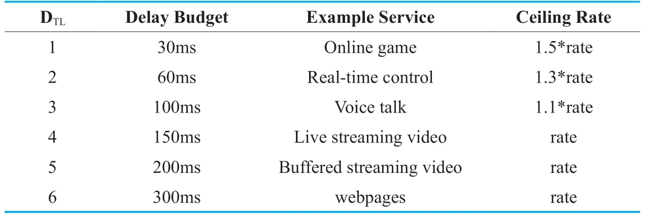
Table II.The DTLdefinition.
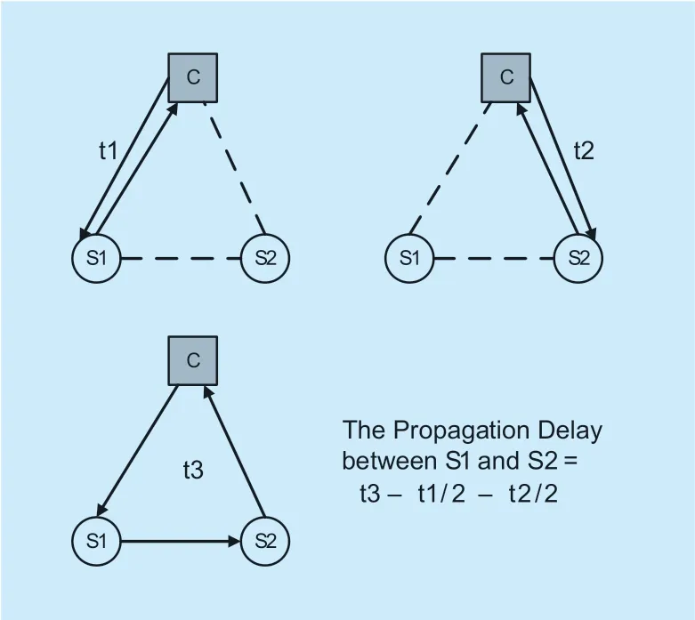
Fig.1.Measuring the propagation delay.
Similar to the DTLdefinition,the links of the network are grouped proportionally into 6 categorizes corresponding to the DTL.We set the Link Delay Level (LDL) to describe the propagation delay,ranging from 1 to 6.The little value means that the link has a lower propagation delay.
IV.DESIGN
In this section,we elaborate the design of the decoupled scheme.In order to achieve the decoupled control,we set that the bandwidth configuration has the intra-queue pattern while the delay control works in the inter-queue mode.
Figure 2 illustrates the layered architecture of this scheme.The QoS policy is the core design of this scheme,including the QDMS and the CPDR.The User Interface takes charge of the interaction with the subscribers.The Network Status module tracks the network status periodically.The Database is required to store the demands,the network status as well as the executory QoS policy.
4.1 Queue delay management scheme
The QDMS can manage the queues configuration in the data plane in order to provide the differential queuing delay.In our design,we leverage the HTB as the queuing algorithm.The HTB is a mature approach.It can provide the deterministic bandwidth control.It can set the guaranteed bandwidth as well as parameters for traffic burst.
The QDMS works in the inter-queue pattern,through arranging the priorities of the queues to make them be processed sequentially.
A piece of route decision can be split into a list of egress ports.Each port in the list should be configured a queue with the QoS setting.We select the rate,ceil,and the priority as the QDMS indicators.The rate can be set directly from the subscriber’s demand.The ceil means the permitted maximum burst rate.The ceil value is set from the DTL,as shown in Table II.
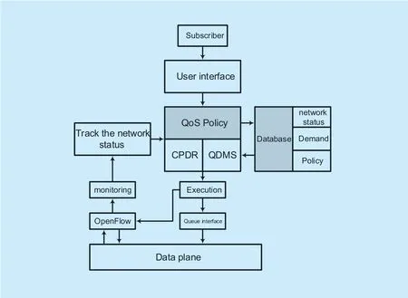
Fig.2.The decoupled scheme layered architecture
The priority of the queue is decided by the service DTL.We divide 13 priorities for each link.And every 2 priorities correspond to 1 DTL.The lower priority value means a higher priority.The priority 1 is reserved for network status tracking for the purpose of ensuring the tracking accuracy.The rest 12 priorities are allocated to the 6 DTLs in sequence.For instance,the DTL2 corresponds the priorities 2 and 3,the priorities 4 and 5 are belonging to DTL3,and so forth.
The priority decision inside each DTLis relative to the bandwidth demand.The controller can compute the average bandwidth demand of each DTL.If the incoming demand has the bandwidth demand which lower than the average value,it should be allocated the latter priorities,in other words the larger value.In contrast,if the demand is larger,the preferential priority should be set.For instance,assuming that the average rate of the DTL2 service is 10Mbps.If the incoming demands have the bandwidth 8Mbps as well as the DTL2,it should be allocated the queue priorities 3.
The QDMS takes charge of configuring the queues either.It configures the queues through a certain protocol which required to be implemented by the developer.Because different facilities have different queue configuration interfaces.The configuration parameters contain the QN,the rate,the ceil,as well as the priority.Because each queue requires a value to number it,thus we utilize the QNas the value.The configuration must be executed together with the route execution.In other words,the queue configuration messages should be sent accompanying with the Flow-Mod messages.
4.2 CPDR weight design
The CPDR can provide the differential propagation delay route.The OpenFlow allows the centralized route decision thus it easy to deploy a new route algorithm in the network.The CPDR is a passive route so that only the flows can trigger the calculation.
The CPDR must satisfy the demands of the subscribers,including the bandwidth,and the DTL.The CPDR requires several statistical values of the network status,which are shown as following.
(1) LDL:The link delay level of each links.
(2) be:The benotates the bandwidth occupied by the higher priority flows.For instance,if the demand has the DTL3,all the DTL1 and 2 in this link should be included in be.
(3) bt:the total bandwidth of each link.
The CPDR can read these indicators from the database directly according to figure 2.Because the CPDR is a reactive route,it should be constrained by the demands.In Table III we illustrate the constraints of the CPDR.
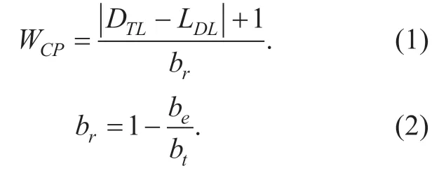
The design of the cost in the Dijkstra should take all the constraints into consideration.We define the WCPto notates the link cost in the CPDR.The lower WCPmeans that the link is more suitable for this service.The WCPis expressed in Equation (1) and (2):
The CPDR should only select the links that have the remaining bandwidth larger than the bandwidth demand.Hence in the process,all the bandwidth-unsatisfied link’s WCPis set to the Infinite (INF).
The molecule of the WCPequation is the absolute value of the difference between the DTLand the LDL.This difference can make the links having the LDLclosed to the DTLto be selected preferentially,which can satisfy the DTLconstraint.
We define the bras the relative remaining bandwidth ratio of the links in the perspective of the incoming demands.The relative remaining bandwidth is remaining resource that would be occupied at present.It’s the difference between the total bandwidth and the higher priorities flows’ bandwidth.The bris the value of the relative remaining bandwidth that has been manipulated by the normalization processing.The brcan help the CPDRdecrease the competition of each service.
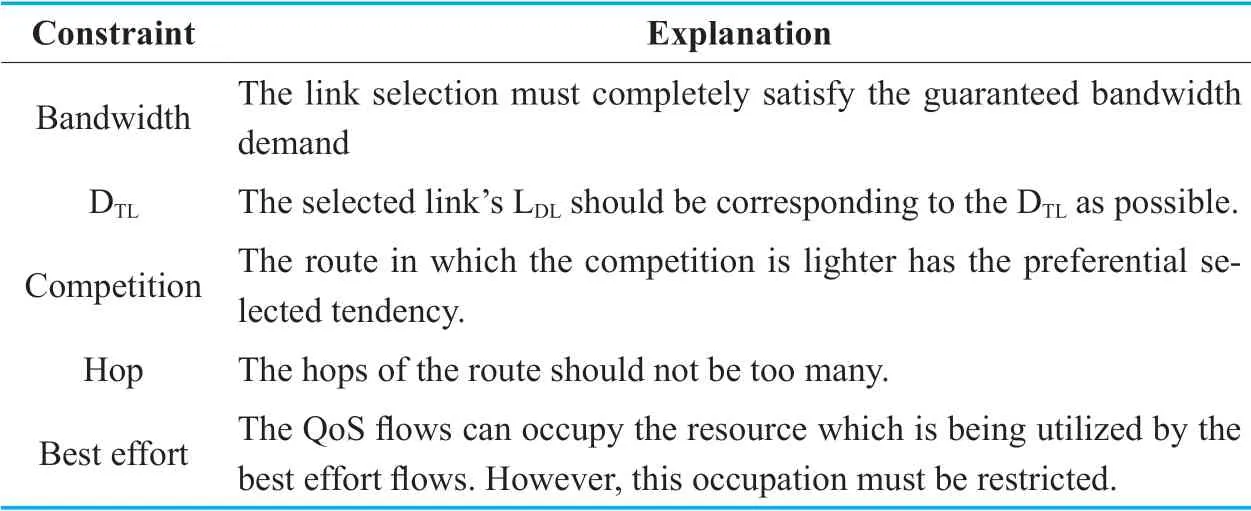
Table III.The CPDR constraints.
The other constraints namely the Hop as well as the Best effort are taken into consideration in the CPDR processing period.
4.3 CPDR process
The controller can get the Packet-In message when a packet encounters an OpenFlow switch in which there’s no matched flow entry.The Packet-In message can trigger the CPDR calculation.
The controller firstly imports the required data from the database.And subsequently,it organizes the data into 2 matrixes namely the MBWand the MLD.The MBWnotates the adjacent matrix of the relative remaining bandwidth,while the MLDrepresents the adjacent matrix link’s propagation delay.The topology is treated as a digraph so that the MBWand the MLDmay be unsymmetrical.
Besides the MBWand the MLD,the inputs of the CPDR still contains the admin-defined values.The administrator needs to set the LDLratio,in order to group the links according to their propagation delay.The demands are the input value too.The CPDR starts the process with the inputted quintuple containing the demand,the bt,the MBW,the MLD,and the LDLratio,as shown in Equation (3).

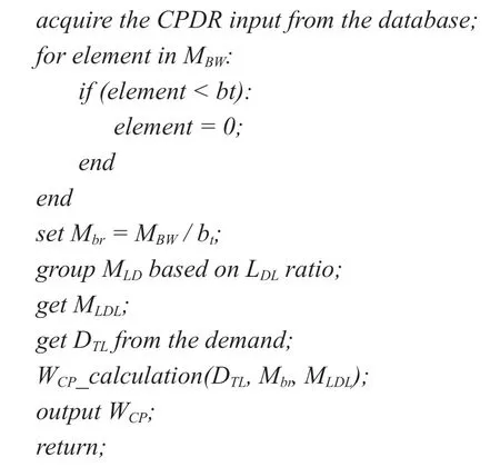
The inputted quintuple can generate the WCPmatrix.The CPDR firstly compares the bandwidth demand to the elements of MBWone by one to judge the acceptability.The elements less than the bandwidth demand should be set to 0.The updated MBWremoves all the unsatisfied links from the alternatives.Then,the CPDR divide the MBWby the bt,and the result is the Mbr.

The LDLratio is the basis of the links grouping.The CPDR ranges the all directed links in the sequence of ascending according to MLD.Then the CPDR groups the links and assigns the LDLto them.Assuming that the LDLratio is the 2:2:2:2:1:1,the 20% links of the minimum propagation delay are allocated the LDL1.When all the links have been grouped,the CPDR output the LDLmatrix MLDLfor the WCPcalculation.The elements of the MLDLis the LDLvalue of the link.
The DTLdemand can be acquired directly from the demands.The DTL,the Mbras well as the MLDLare the inputs of the WCPcalculation.

The CPDR can get the WCPaccording to Equation 1.The WCPcan describe the suitable degree of the links to the demand.The smaller means the more suitable.In particular,if the one certain link’s bris 0,its WCPis set to INF so that it would not be selected.The WCPcorresponds to the demand one by one so that it cannot be reused.After the WCPcalculation,the CPDR starts the pathfinding process.The WCPcalculation can be interpreted by the following pseudocode.
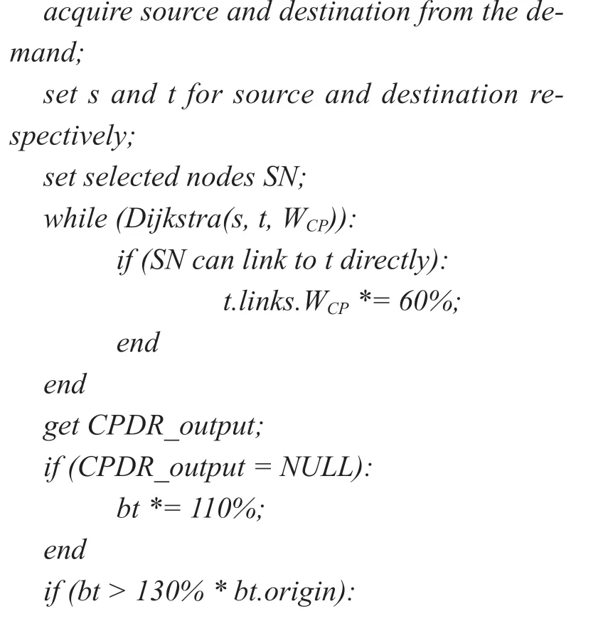
The CPDR is a modified Dijkstra algorithm,thus it should follow the basic Dijkstra procedures.The rules for pathfinding in CPDR is the same to the typical Dijkstra.However,after each pathfinding process step,the CPDR should judge whether the already selected nodes have the direct link to the destination.If there exists at least one node can direct link to the destination,the WCPof all the links which can directly link to the destination should be decreased by 40% after each step.The mechanism can avoid too many hops in the route,which can meet the Hop constraint.
When the destination node is selected,the CPDR ends and outputs a list of intermediate nodes and their egress ports.An fictitious instance of the CPDR output is illustrated in Equation 6.

Considering that the network resources may be not sufficient for the incoming demands,thus the CPDR should fix this case.The CPDR will increase the btby 10% if it cannot find a route of which all the links beare larger than the bandwidth demand.The btincreasing means that the resources of the best effort flows are occupied by the new coming QoS flows.If the bthave been increased more than 30% in total but the network is still unsatisfied,the controller will reject the incoming service demand,for which the resource is insufficient.Thus,the Best Effort constraint can be met through this mechanism.The pseudocode below elaborates the CPDR processing.
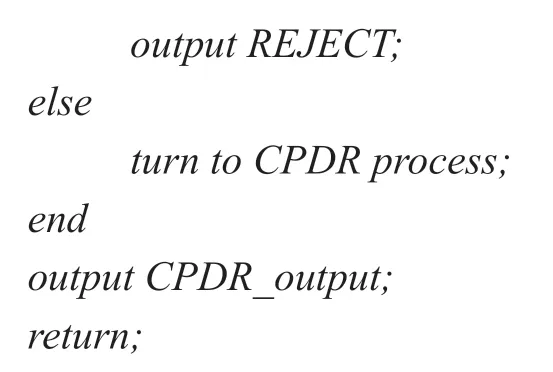
The CPDR output contains the intermediate interfaces in the route.The route policy is executed in the form of the flow entries.Once the route is generated,the QDMS can get the interfaces required the queue configuration.Thus,the CPDR output is the QDMS input too.
4.4 Dynamic update
Because the QoS flows may suspended for a time,the controller must dynamically update the QoS configuration in the data plane for the temporary releasing of resources.The controller can judge the flows existence through the Read-Stat message.
If the flow has been suspended over 10mins,the controller will remove its flow entries as well as the queue configurations in the data plane to release the cache resource.However,its demands and the QoS policies are still maintained in the data base.If the flow comes again,the controller can get the previous QoS polices at once from the data base.And subsequently,the QoS policies should be executed.The demands and the polices in the database can only be deleted by the delete message posted by the subscriber.
V.PERFORMANCE EVALUATION
In this section,we introduce some experiment conducted to expose the performance of this decoupled QoS scheme.We’ve built a demo prototype of this scheme on an RYU[26] controller.The evaluation experiments were performed from two perspectives respectively.The first experiment is measuring the performance of the QDMS,which is emulated on the prototype program.The other is the CPDR simulation conducted by a Python program with random topologies and demands.
5.1 Prototype implementation
We implemented this scheme based on the RYU,an open source OpenFlow controller programmed by Python.Some essential functions like the topology discovery are the builtin functions of RYU.The functions of this scheme are programmed according to figure 2.We built the User Interface by invoking the Python cmd class.
The User Interface is in the form of CLI,in which the subscriber can express their demands through the command line.The demands are converted into the JSON in the User Interface,and posted to the controller through the REST API.
We selected MySQL as the database in this scheme prototype.We created 5 tables in the database for storing the required information.The tables’ names and contents are shown in Table IV.
The queue configuration interface is also required in the prototype implementation.The interface is programmed facing the OpenvSwitch,a virtual OpenFlow switch that can run on the Linux.We leverage the Linux TC (Traffic Control) for the queue configuration execution.The TC can operate the queue in the network interface,including creating,modifying as well as deleting.The TC is configured through the CLI,thus it cannot be directly invoked by the controller.We developed a program by encapsulating the TC command line into several callable interfaces.And the controller can configure the queues by passing the parameters to this program.This program has an affiliated progress running on the hostmachine of the OpenvSwitch.This progress takes charge of acquiring the queue configuration message from the controller and executing it.The message is transmitted through Socket,and executed via the popen() pipeline.
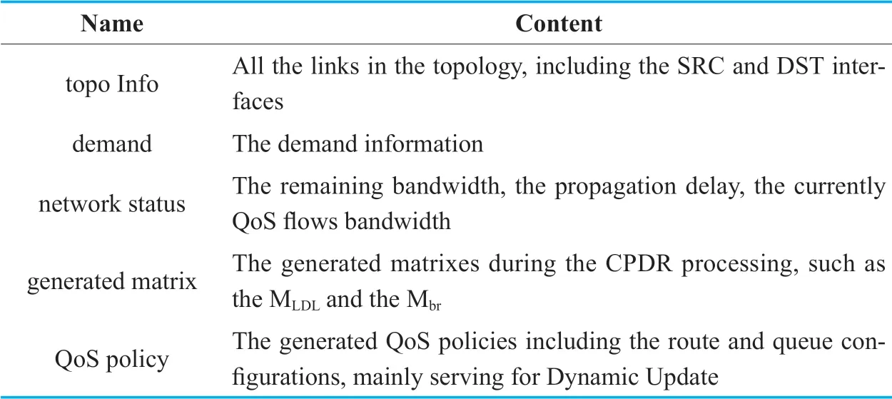
Table IV.The tables in the database.
5.2 QDMS emulation
We emulated the QDMS in the prototype for measuring the performance of the queuing delay management.The experiment is deployed on a virtual Ubuntu 14.04 machine with a kernel 4.2.0-42-generic,which is embedded on ESXI 6.0.0.The virtual machine has two logical CPUs and 16GB RAM.Its host server is DELL PowerEdge R730 with two Xeon E5-2609 v3 CPUs,128GB RAM and 1TB SSD storage.
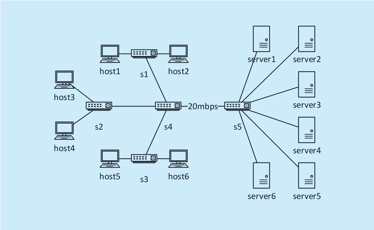
Fig.3.The QDMS emulation topology.
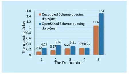
Fig.4.The queuing delay in QDMS emulation.
The emulation topology is organized by the Mininet with the OpenFlow 1.3 protocol setting.The topology is demonstrated in figure 3.The server and host are group into pairs according to their numbers,as well as the same number DTL.For example,the host1-server1 group has the DTL1.The link between s4 and s5 is the bottleneck,with the restricted bandwidth 20Mbps.
The rate can affect the queuing delay if the network resource is insufficient.Thus,we set the test rate the same for the flows in order to eliminate the rate effect.The DTL1 to DTL5 have the same rate 3Mbps.The DTL6 is treated as the back ground flow for fully occupied the link bandwidth,having the rate 10Mbps.The DTL1 to 4 are the QoS flows while the DTL5 treated as the best effort.The DTL5 has the higher priority than DTL6.We leverage the Iperf [27] to generate the traffic from the servers to the hosts.
We utilize a Python script to send the ICMP[28] messages periodically for mearing the RTT.Because only the bottleneck link is restricted,thus the RTT can be treated as the queuing delay in s4 and s5.We ran this scheme and the OpenSched respectively,and get 100 pieces of delay data for each DTL.We calculate the average value for each DTL.And the results are illustrated in figure 4.
Figure 4 shows the emulation results.The DTL5 is has the longest delay both in the decoupled scheme and the OpenSched for it’s the best effort and the network resource is fully occupied.In the decoupled scheme,the queuing delay has the sequenced distribution.The smaller DTLflows experience the shorter delay,namely the 0.12ms,0.17ms,0.23ms,and 0.25ms,from DTL1 to DTL4 respectively.Comparing to OpenSched,the decoupled scheme reduces the delay by 50%,50%,25.8%,and 3.8% for DTL1 to DTL4 respectively.
The QDMS emulation verifies that the decoupled scheme can effectively manage the queuing delay.The flows with higher priority have the lower queuing delay at the macroscopic level.
On the other hand,we record the rate report from the Iperf server end for acquiring the bandwidth in different DTL.The result is shown in figure 5.
Because the rate setting is the same for different DTL,thus they have the same throughput rate.The decoupled scheme and the Open-Sched both leverage the HTB to manage the rate.The experiment verifies that the bandwidth management is effective.In turn,the different DTLflows have the different queuing delay in the decoupled scheme,while they have the same rate,which proves that the delay control is decoupled from the bandwidth control.
5.3 CPDR simulation
The CPDR simulation is performed based on the same host to the QDMS emulation.The CPDR simulation is programmed by a Python program.This program can generate the topologies randomly,in the form of the random CPDR input elements.The atio is set to 2:2:2:2:1:1.The topologies have 30 nodes and 120 links.The bandwidth of the links ranges from 1000 to 3000 randomly,without unit.The propagation delay of the links ranges from 0.1ms to 0.5ms.
The demands are constructed randomly.The program selects 2 nodes as the source and the destination.The bandwidth demand ranges from 1 to 20,as well as the random DTL.The program accepts all the demands and calculates the route for them.Once the topology becomes unconnected,the simulation ends and outputs the results.The results contain the total propagation delay of each demand and the selected links’ average delay for each DTL.
We ran the experiment for the decoupled scheme and the OpenSched with OSPF[29] respectively.The decoupled scheme experiment is executed prior,and its topologies and the demands are stored in the database.In the OpenSched experiment,the topologies setting and the demands are read from the database,which ensures the two experiments have the same conditions.In the decoupled scheme experiment,there are 4383 demands accepted and the OpenSched adopted 4027 demands.We compute the average propagation delay for each demand.And the results are shown in Table V.
Compared with OpenSched,the decoupled scheme can provide the differential propagation delay according to Table V.The propagation delay has the increasing trend from DTL1 to DTL5.Figure 6 illustrates the propagation delay difference between the two approaches.For the DTL1 and DTL2,the propagation delay can be reduced by 0.28ms and 0.04ms respectively.In other words,the decoupled scheme can reduce the propagation delay for DTL1 and DTL2 by 26.2% and 3.8%.
The links selection in CPDR and Opensched are also different.Thus,we recorded the average link delay for each DTLin this experiment.The average link delay means the total propagation delay divided by its route hops.The results are illustrated in Table VI.
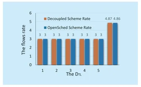
Fig.5.The rate in different DTL.

Table V.The Propagation delay(ms) of each demand.

Table VI.The average link delay(ms) of each demand.
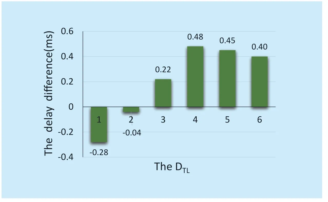
Fig.6.The propagation delay difference.
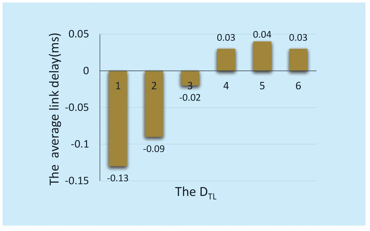
Fig.7.The average link delay.
Table VI illustrates that the CPDR has the delay-related link selection in the route process.For DTL1 to DTL3,the selected links’ average delay is lower than the OpenSched.The average link delay in DTL1 is 0.26ms while in OpenSched it’s 0.39ms.Figure 7 demonstrates the comparison of them.In the decoupled scheme,the average link delay is lower by 33.3%,22.5%,and 5% from DTL1 to DTL3.
The experiments in this section verify the effectiveness of the decoupled scheme in the delay control.The QDMS can manage the queuing delay while the CPDR can operate the propagation delay.The higher priority flows (the lower DTLvalue) have the lower delay in the CPDR,especially obvious for the DTL1 and DTL2.Through these experiments,we can conclude that this scheme can satisfy the time-sensitive services’ demand.Meanwhile,the decoupled scheme can also provide quantitative bandwidth control,as verified in Section V-B.And the bandwidth control works independently of the delay control.
VI.CONCLUSION
In this paper,we propose the decoupled QoS scheme in the OpenFlow networks to meet the QoS demands of various indicators.This scheme decouples the delay control from the bandwidth control.It leverages the HTB queue for managing the bandwidth in each created queue.We design the QDMS and the CPDR for managing the queuing delay and the propagation delay respectively.The bandwidth control is intra-queue while the QDMS and the CPDR both work in the inter-queue pattern.We built a prototype of this scheme on an RYU controller,and performed the experiment on it to evaluation the QDMS performance.Subsequently,we conducted some other experiments for the CPDR.The results verify the decoupling.The decoupled scheme can reduce the flows in higher priority effectively comparing to OpenSched.
However,the decoupled scheme is not full-featured at present.The queuing theory[30] indicates that the queues have the steady length if the traffics have the Poisson arrival distribution.Thus the queue length can affect the packet loss ratio,because the too short queue length setting may not satisfy the queue’s steady length.Hence,we are considering introducing the queue length control into this scheme to provide the packet loss ratio optimizing.For instance,we can set a longer length for the queue in which transmitting the flow having the highly burst probability.
ACKNOWLEDGEMENT
The work described in this paper was supported National Natural Science Foundation of China (Project Number:61671086) Consulting Project of Chinese Academy of Engineering (Project Number:2016-XY-09).
- China Communications的其它文章
- Research on Mobile Internet Mobile Agent System Dynamic Trust Model for Cloud Computing
- EEG Source Localization Using Spatio-Temporal Neural Network
- DDoS Attack Detection Scheme Based on Entropy and PSO-BP Neural Network in SDN
- Constructing Certificateless Encryption with Keyword Search against Outside and Inside Keyword Guessing Attacks
- Customizing Service Path Based on Polymorphic Routing Model in Future Networks
- Energy-Efficient Joint Caching and Transcoding for HTTP Adaptive Streaming in 5G Networks with Mobile Edge Computing

