
Definition of failure criterion for frozen soil under directional shear-stress path
2019-06-11 03:05:24DunChenWeiMaGuoYuLiZhiWeiZhouYanHuMuShiJieChen
Dun Chen,Wei Ma,GuoYu Li,3*,ZhiWei Zhou,YanHu Mu,ShiJie Chen
1. State Key Laboratory of Frozen Soils Engineering, Northwest Institute of Eco-Environment and Resources, CAS, Lanzhou,Gansu 730000,China
2.State Key Laboratory for GeoMechanics and Deep Underground Engineering,China University of Mining and Technology,Xuzhou,Jiangsu 221116,China
3.Da Xing'anling Observation and Research Station of Frozen-Ground Engineering and Environment,Northwest Institute of Eco-Environment and Resources,Chinese Academy of Sciences,Jiagedaqi,Heilongjiang 165000,China
ABSTRACT A series of directional shear tests on remolded frozen soil was carried out at -10 °C by using a hollow cylinder apparatus to study failure criterion under a directional shear-stress path. Directional shear tests were conducted at five shear rates(10, 20, 30, 40, and 50 kPa/min) and five intermediate principal stress coefficients (b=0, 0.25, 0.5, 0.75, and 1), with the mean principal stress (p=4.5 MPa) kept constant.The results show that the torsional strength and the generalized strength both increase with the increase of the shear rates.According to the failure modes of frozen soil under different shear rates,the specimens present obvious plastic failure and shear band; and the torsional shear component dominates the failure modes of hollow cylindrical specimens.A shear rate of 30 kPa/min is chosen as the loading rate in the directional shear tests of frozen soil.The shape of the failure curve in the π plane is dependent on the directional angles α of the major principal stress. It is reasonable to use the strain-hardening curves to define the deviatoric stress value at γg=15% (generalized shear strain)as the failure criterion of frozen soil under a directional shear-stress path.
Keywords: frozen soil; hollow cylinder apparatus; intermediate principal stress coefficient; failure criterion; directional shear-stress path
1 Introduction
Failure criterion is not only an indispensable technical index in engineering design, but it is also the basis for the further study of soil mechanics (Li, 2005). In other words, failure criterion means the strength point of soil. So the failure criterion plays an important role in soil mechanics and engineering.According to the experimental results of soil mechanics, the stress-strain curves of soil under complex stress paths can be divided into strain-softening and strain-hardening curves(Shen,2000;Yin,2007).When the stress-strain curves present softening phenomena, the peak values of stress are generally taken as the failure criterion. However,there is not a unified failure criterion for the strain-hardening curves under complex stress paths.
Generally speaking, for the stress-strain curves of soil, the failure criterion of the strain-hardening curves can be defined by two methods. First, the stress corresponding to the major principal strain is taken as the failure criterion, such as ε1=15% in the triaxial tests(Lai et al., 2010, 2016; Xu et al., 2011; Zhou et al.,2016, 2017, 2018). Second, four of strain components(axial strain (εz), shear strain (γzθ), radial strain (εr),and circumferential strain(εθ))can be obtained by hollow cylinder tests under complex stress paths (Hight et al., 1983; Yoshimine et al., 1999; O'Kelly and Naughtion, 2009; Jiang et al., 2012). Therefore, the deviatoric stress corresponding to the generalized shear strain γgis taken as the failure criterion for the strain-hardening curves (γg=5%, 8%, 10%, and 13%)(Shen et al., 1996; Kumruzzaman and Yin, 2010;Nishimura et al., 2010; Wen et al., 2010; Lade et al.,2013;Zhang et al.,2015).
Considering that, up to the present, no failure criterion could describe the failure behavior for frozen soil under complex stress path; the objective of this study was to define a failure criterion for further determinations of the mechanical properties of frozen soil.In this study, experimental investigations of directional shear tests, conducted on the hollow cylindrical specimens of frozen soil under different shear rates and intermediate principal stress coefficients, were made. The optimal loading rate of directional shear tests for frozen soil was proposed. And based on the experimental results in the π plane, the failure criterion of frozen soil for strain hardening under a directional shear-stress path was defined.
2 Test conditions
2.1 Test preparation
The Hollow Cylinder Apparatus for Frozen Soil(FHCA-300)was used for this experimental investigation. The apparatus is able to independently control the axial load (W), torque (MT), internal cell pressure(pi), external cell pressure (po), and temperature (T)(Hightet al., 1983; Vaidet al., 1990). The measurement range of the temperature control system used in the test is from -40 °C to 80 °C, and the accuracy is±0.01 °C. In this study, the soil used was taken from the Qinghai-Tibet Plateau(Chenet al.,2019).The average water content and the dry density of the tested specimens were 19.8% and 1.9 g/cm3, respectively(Chenet al., 2019). The specimens were prepared as hollow cylinders, 200 mm in height, 100 mm in outer diameter, and 60 mm in inner diameter. Then, the specimens were placed into a hollow cylindrical pressure cell and quickly frozen under conditions of -30 °C for 48 hours.After the specimens were warmed to the temperature of-10°C,and kept at a constant temperature for 12 hours,the directional shear tests began.
2.2 Theoretical derivation of complex stress path
To obtain the complex stress path by hollow cylinder apparatus, it is necessary to convert the generalized stress(shear stress qs,mean principal stress p,the directional angle α of the major principal stress, and the intermediate principal stress coefficient b) into the control parameters of the hollow cylinder apparatus(axial load W, torque MT, internal cell pressure pi, and external cell pressurepo) (Hightet al., 1983; Shen,2007).So,the conversion process is as follows:
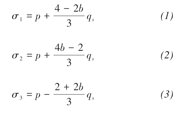
(1) Conversion from generalized stress to principal stress
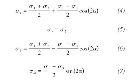
(2) Conversion from principal stress to element stress
(3) Conversion from element stress to control parameters of the hollow cylinder apparatus

where σ1is major principal stress; σ2is intermediate principal stress; σ3is minor principal stress; σzis axial stress; σris radial stress; σθis circumferential normal stress; τzθis circumferential shear stress; riis inner specimen radius; rois outer specimen radius; and rpis loading-rod radius.
Through three conversions, the following formula has been obtained.
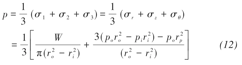
Mean principal stress p:
Shear stress qs:

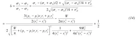
Intermediate principal stress coefficient b:
Directional angle α of the major principal stress:
1) when σz>σθ, W >πrori(po- pi)+po
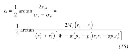
And α ∈( - 45°,45°).
2)when σz<σθ, W <πrori(po- pi)+po
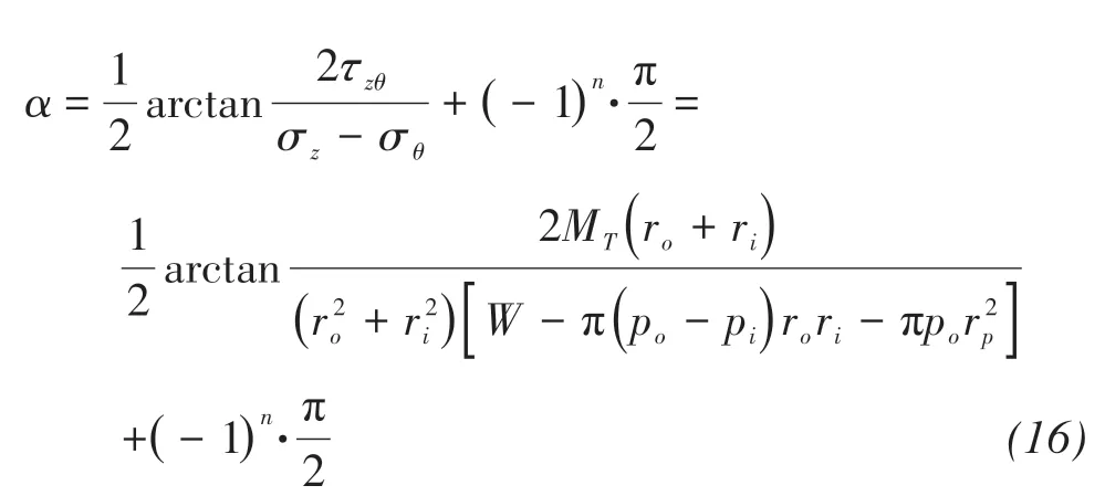
In(16),when τzθ≤0,n=1;when τzθ≥0,n=2.
And α ∈[ - 90°, - 45°]∪[45°,90°].
The shear rate (q·s) is usually used to control the process of the directional shear test by using the hollow cylinder apparatus. Based on the theoretical derivation of the complex stress path,the loading mode of the directional shear tests (shear rate) is dependent on the relative magnitude of the axial load, torque, internal cell pressure, and external cell pressure. The values of loading parameters at different shear rates are obtained by calculating the above formulas.
2.3 Directional shear-stress path
The stress path of the directional shear tests can be divided into two steps, as shown in Figure 1. First,the axial load,torque,internal cell pressure,and external cell pressure were loaded, following stress path OA, to reach the tested mean principal stressp. Second, the shear stress qswas increased at a constant rate until the axial strain reached 20% or the torsional shear strain reached 30%, as the path AB shows in Figure 1. During the second step, the mean principal stress p, the directional angle α of the major principal stress, and the intermediate principal stress coefficient b remained constant.
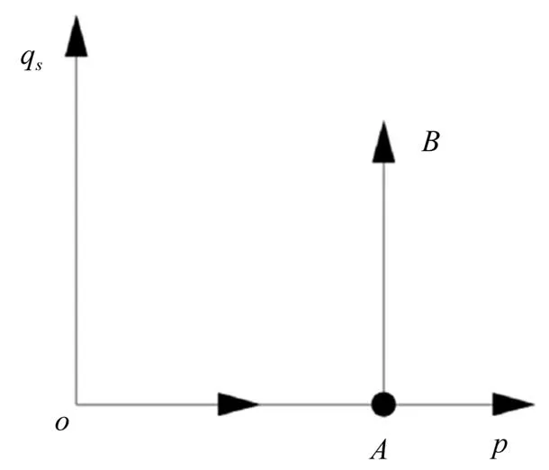
Figure 1 Stress path of directional shear tests
3 Test results and analyses
3.1 Choice of the shear rate in directional shear tests
The loading rate is one of the most important factors in mechanical experiments of frozen soil (Bragg and Andersland, 1981; Li et al., 2004; Du et al.,2016).In order to choose the optimal shear rate of frozen soil,the directional shear tests were conducted under five shear rates (10, 20, 30, 40, and 50 kPa/min)at the temperature of -10 °C. During the directional shear process, the mean principal stress p=4.5 MPa,the directional angle α of the major principal stress α=45°, and the intermediate principal stress coefficient b=0.5 were kept constant.
The experimental relationship between stress and strain at different shear rates is presented in Figures 2-4.From Figure 2, it can be seen that the shape of axial stress-strain curves does not change with the increase of the shear rate. And all the specimens are stretched in the axial direction. The torsional and generalized shear stress-strain curves of frozen soil all perform as strain-hardening phenomena under different shear rates, as shown in Figures 3 and 4. With increase in the shear rate, both the torsional strength and the generalized strength increased.So the shear rate has a significant influence on the torsional and generalized shear stress-strain curves, but that has little effect on the axial stress-strain curves.
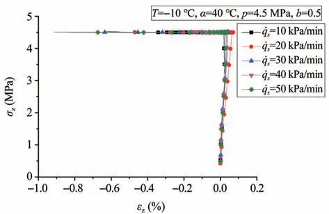
Figure 2 Axial stress-strain curves under different shear rates
Figure 5 shows the failure modes of hollow cylindrical specimens under different shear rates at a negative temperature. All specimens show plastic failure and obvious shear bands.Therefore, the failure modes of hollow cylindrical specimens are not affected by shear rate; and the torsional shear component dominates the failure modes of hollow cylindrical specimens of frozen soil. Based on the analytical results of specimens in the failure process, failure time decreases considerably with increasing shear rate, as shown in Table 1.
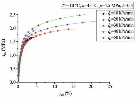
Figure 3 Torsional stress-strain curves under different shear rates
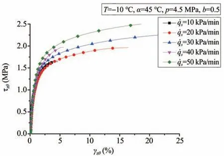
Figure 4 Generalized shear stress-strain curves under different shear rates
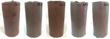
Figure 5 Failure modes of specimens of frozen soil under different shear rates.
In summary, when the shear rate is 30 kPa/min,the data acquisition of directional shear tests for frozen soil is more stable and comprehensive; and the continuous development of the strain component is beneficial to the data supervision of stress - strain curves. So, 30 kPa/min is chosen as the shear rate in the following directional shear tests of frozen soil.
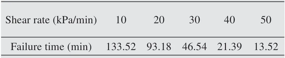
Table 1 Failure time of hollow cylindrical specimens of frozen soil in the directional shear tests
3.2 Definition of the failure criterion for frozen soil
A series of the directional shear tests at p=4.5 MPa, T=-10 °C, and α=30° on frozen soil under the intermediate principal stress coefficients b from 0 to 1 (b=0, 0.25, 0.5, 0.75, and 1) was carried out; the corresponding test results are shown in Figures 6-8.From these figures, it can be seen that the axial and torsional strengths are observed to change with the increasing intermediate principal stress coefficient.However, the intermediate principal stress coefficient has little influence on the relationship between the generalized shear stress and strain.
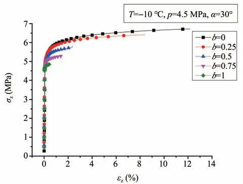
Figure 6 Axial stress-strain curves under different intermediate principal stress coefficients at α=30°
Based on the definition of the stress Lode angle θσand the intermediate principal stress coefficient b (Li,2005), the relationship between the stress Lode angle and the intermediate principal stress coefficient can be obtained (as shown in Equation (17)). Then, from Equation (17), b=0, 0.25, 0.5, 0.75, and 1 are respectively correspondent with θσ=-30°, -16.1°, 0°, 16.1°,and 30° (Chen et al., 2018). So the stress Lode angle of those tests can be presented in the π plane, as shown in Figure 9(Chen et al,2018).
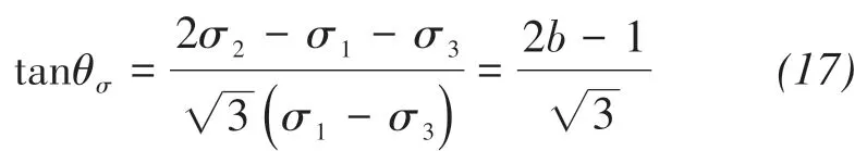
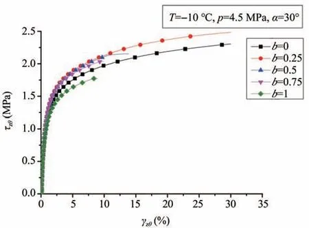
Figure 7 Torsional stress-strain curves under different intermediate principal stress coefficients at α=30°
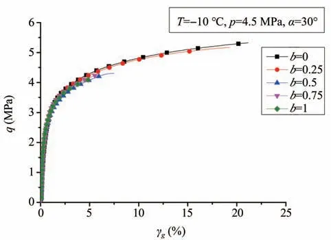
Figure 8 Generalized shear stress-strain curves under different intermediate principal stress coefficients at α=30°
According to the results of the directional shear tests, the deviatoric stress loci can be obtained that correspond to the different generalized shear strains.And Figure 10 shows the deviatoric stress loci with the generalized shear strain ranging from 0.6% to 18% in the π plane under the directional angle of the major principal stress α=30°. From Figure 10, it can be seen that the deviatoric stress loci only at θσ=-30°and -16.1° are presented, when the generalized shear strain is high. However, when the generalized shear strain γg≤5%,the deviatoric stress loci exist completely in the π plane, corresponding to the different stress Lode angles. So the failure curves can be plotted by the deviatoric stress loci. It can be seen that the shape of the failure curves does not change with the generalized shear strain ranging from 0.6% to 8% in the π plane. And with the increase of generalized shear strain, the failure curves are getting closer and closer to each other.
The shape of the failure curve in the π plane remains constant under two directional angles of the major principal stress(α=30°and 0°),no matter what the generalized shear-strain change (as shown in Figure 11) (Chen et al., 2019). By comparing Figures 10 and 11,it can be seen that the shape of the failure curve in the π plane is dependent on the directional angles α of the major principal stress. When the directional angles of the major principal stress α=30°, the shape of the failure curve is a circle. However, when the directional angles of the major principal stress α=0°, the shape of the failure curve is a smooth, curve-sided triangle. When the generalized shear strain reaches 15%, the shape of the failure curve remains constant under the different directional angles α of the major principal stress. Therefore, the deviatoric stress at γg=15% is taken as the failure criterion of frozen soil under the directional shear-stress path.
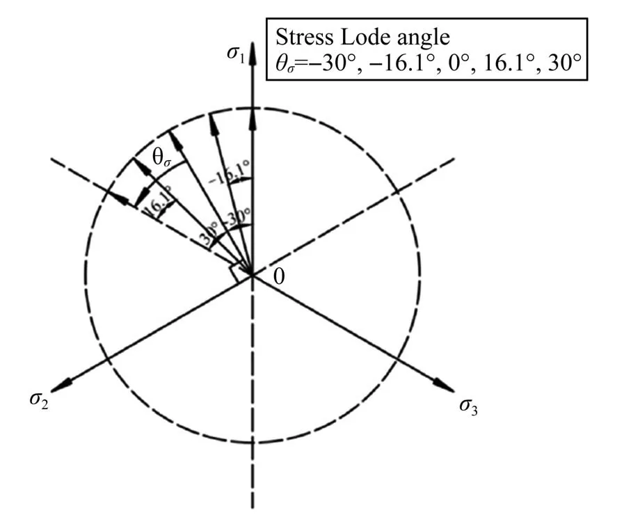
Figure 9 Stress Lode angles in the π plane

Figure 10 Failure curves of frozen soil under α=0°with different failure criteria in the π plane
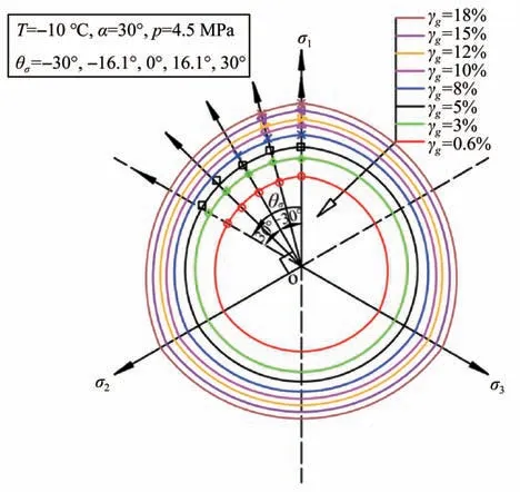
Figure 11 Failure curves of frozen soil under α=30°with different failure criteria in the π plane(Chen et al.,2019)
4 Conclusions
Based on the experimental data, a shear rate was proposed in order to reasonably conduct the directional shear tests for frozen soil;and according to the analytical data results of the directional shear tests on various values of the intermediate principal stress coefficients,the failure criterion of frozen soil under a directional shear-stress path was defined. Therefore, the following conclusions were reached, based on the results obtained:
(1) The torsional and generalized shear stressstrain curves of frozen clay present strain-hardening phenomena with different shear rates under a directional shear-stress path. And with the increase in the shear rate, the torsional strength and the generalized strength both increased.
(2) The shear rate has little influence on the failure modes of hollow cylindrical specimens of frozen soil, and the torsional shear component dominates the failure modes.The shear rate of 30 kPa/min is chosen in the directional shear tests of frozen soil.
(3)The shape of the failure curve in the π plane is dependent on the directional anglesαof the major principal stress.According to the evolution characteristics of the failure curves with the increase of generalized shear strain, the deviatoric stress at γg=15% is taken as the failure criterion of frozen soil for strain hardening under a directional shear-stress path. Meanwhile, when the stress-strain curves present softening phenomena, the peak values of stress are generally taken as the failure criterion.
Acknowledgments:
The work presented in this paper was supported by the National Natural Science Foundation of China(Nos. U1703244 and 41672310); the State Key Laboratory for GeoMechanics and Deep Underground Engineering, the China University of Mining and Technology (SKLGDUEK1904); the Strategic Priority Research Program of the Chinese Academy of Sciences (Grant No. XDA2003020102); the National Key Research and Development Program(2017YFC0405101); the Major Program of Bureau of International Cooperation, the Chinese Academy of Sciences (131B62KYSB20170012); the Research Project of the State Key Laboratory of Frozen Soils Engineering (Grant No. SKLFSE-ZY-16); the Science and Technology Major Project of Gansu Province(143GKDA007); the National Natural Science Foundation of China (No. 41801038); and the Science and Technology Planning Project of Gansu Province (No.18JR3RA376).
 Sciences in Cold and Arid Regions2019年6期
- Sciences in Cold and Arid Regions的其它文章
- Spatiotemporal variations in moisture conditions across Monsoon Asia during the last 500 years
- An evaluation of soil moisture from AMSR-E over source area of the Yellow River,China
- Vegetation change and its response to drought in Inner Mongolia of northern China from 1998 to 2013
- Characteristics of climate and melt runoff in the Koxkar Glacier River Basin,south slope of the Tianshan Mountains,Northwest China
- Editors-in-Chief Guodong Cheng and Ximing Cai
- Relationship between ponding and topographic factors along the China-Russia Crude Oil Pipeline in permafrost regions