Optimization of gas tungsten arc w elding parameters for the dissimilar welding between AISI 304 and AISI 201 stainless steels
Wichan Chuaiphan ,Loeshpahn Srijaroenpramong
a Department of Mechanical and Industrial Engineering,Faculty of Engineering,Rajamangala University of Technology Krungthep,2 Nanglinchee Road,Tungmahamek,Sathorn,Bangkok,10120,Thailand
b Department of Metallurgical Technology,Faculty of Education,Rajamangala University of Technology Krungthep,2 Nanglinchee Road,Tungmahamek,Sathorn,Bangkok,10120,Thailand
Keyw ords:Dissimilar w eldment AISI 304 stainless steel AISI 201 stainless steel Gas tungsten arc w elding(GTAW)Nitrogen Corrosion behavior Mechanical behavior
A B S T R A C T This present study applied gas tungsten arc welding in order to join AISI 304 and AISI 201 stainless steels.The objective w as to f i nd the optimum w elding condition that gave a w eld bead in accordance w ith DIN EN ISO 25817 quality level B,pitting corrosion potential of the w eld metal of not less than that of the AISI 304 base metal and a ratio of delta-ferrite in austenite matrix of the w eld metal of not low er than 3%.Such a ratio is a criterion widely accepted to protect the w eld metal from solidi f i cation cracking.At the welding current of 75 A and by using pure argon as a shielding gas 0 to 8 vol.%and applying a welding speed in the range of 2-3.5 mm·s-1 was found to give a complete w eld bead w ith an increased depthper-w idth ratio(promote w eldability).For w elding speed in the range of 3 and 3.5 mm·s-1(promote corrosion resistance).Increasing the w elding speed in such a range decreased the amount of delta-ferrite in the austenite matrix,and increased the pitting corrosion potential of the w eld metal to be 302 m VSCE.This value w as still low er than the pitting corrosion potential of the AISI 304 base metal.Mixing nitrogen in argon shielding gas increased the nitrogen content in the w eld.The optimum condition was found when using a w elding speed of 3 mm·s-1 and mixing 1 vol.%of nitrogen in the argon shielding gas(promote w eldability and corrosion resistance).Pitted areas after potentiodynamic test w ere observed in the austenite in w hich its Cr content w as relatively low.
1.Introduction
Austenitic stainless steel grade AISI 304 is a material generally used due to its excellent corrosion resistance.In this alloy,18 w t%chromium(Cr)is added to improve the corrosion resistance,w hereas alloying nickel(Ni)at 8 w t%is used to stabilize the austenite phase[1-3].It is know n that the price of nickel is relatively high as compared to other austenite forming elements,particularly manganese[4,5].As a result,AISI201 w as developed to be an austenitic stainless steel w ith the same 18 w t%of chromium.How ever,manganese is added in this steel at 7 w t%in order to stabilize the austenitic phase and provides corrosion resistance to some extent instead of the nickel and because of this effect the nickel is reduced from 8-10 w t%to 3-5 w t%[4,5].
An industrial question that inspired this w ork w as w hether it w ould be possible to replace stainless steel grade AISI304(that has partly failed in service)w ith a cheaper stainlesssteel grade AISI201.If a design of a w elding process is applied to join both of these materials,the optimum w elding parameters must be able to provide acceptable w eld bead shape,appropriate microstructure and also apply pitting corrosion resistance to the w eld.It has been w idely reported that the appropriate delta-ferrite in the austenite matrix of the w eld should be in the range of 3-10%[2,6,7].If the delta-ferrite in the w eld is less than 3%,it is susceptible to solidif i cation cracking.This is due to the low amount of ferrite phase in w hich sulphur could dissolve.In this condition,sulphur may form iron sulphide during solidi f i cation and therefore induce solidi f i cation cracking in the w eld[6,7].On the other hand,if delta-ferrite fraction is higher than 10%,there is a tendency that ferrite forms netw orks surrounding the austenite matrix,resulting in the galvanic corrosion betw een these tw o phases[1-3].To control the microstructure of w eld metals for stainless steel,nitrogen in the shielding gas has been used in the w elding process in order to increase the amount of nitrogen,an austenite stabilizer,in the w eld[8-11].Increasing nitrogen content in stainless steel has also been found to improve its pitting corrosion properties.An empirical formula of Pitting Resistance Equivalent Number(PREN)as a function of w t%of Cr,Mo and N has been w idely used as the pitting corrosion index for stainless steels containing different compositions[2,3].Various mechanisms have been proposed to explain the bene f i cial effect of nitrogen on the corrosion resistance of stainless steels,for example the ammonium or nitride formation during the corrosion process[11,12].

Table 1Chemical compositions of the studied steels.
According to a survey of the literature,there have not been any published w orks that apply a mixing technique of nitrogen in the shielding gas in order to improve the microstructure and corrosion behavior for the w elding of dissimilar metals.This is particularly the case betw een AISI304 and AISI201 stainless steel.The objective of this w ork w as to f i nd the optimal process parameter values for gas tungsten arc w elding(w elding speed and nitrogen percent mixed in argon shielding gas)to give a w eld metal containing 3-10%of delta ferrite,and a pitting corrosion potential comparable to those of AISI 304 base metal.
2.Experimental
AISI 304 and AISI 201 stainless steels w ere used as base metals in this study.The chemical compositions measured by emission spectroscopy are listed in Table 1.It should be noted that the AISI 304 had 17.61 w t%Cr,8.85 w t%Ni and 3.97 w t%Mn.The AISI 201 contained 17.40 w t%Cr,w hich w as similar to those of AISI 304.How ever,Ni in AISI 201 w as decreased to 3.13 w t%,and Mn w as added by 7.38 w t%.Nitrogen,w hich is an austenite stabilizer and an element that increases PRENw as also added to AISI201 at 0.26 w t%.The dimension of the sample for w elding w as 200 mm×100 mm×2 mm.The w elding w as carried out using an automatic gas tungsten arc w elding(GTAW)process that used a square butt joint w ithout f i ller material.The w elding parameters used are listed in Table 2,this w elding parameter w as decided through a review of the literature on austenitic stainless steel joints and several experiments until the w eld metal w as acceptable in reference to DIN EN ISO 25817 quality level B[13].
After w elding,all the w elds w ere examined by using nondestructive methods,such as visual and radiography tests.The w idth of the w elds on the face and root sides w ere measured by a metallographic method(Olympus model:SZ61 Stereo Zoom microscope).The acceptable w eld bead was referenced to DIN EN ISO 25817 quality level B.Chemical compositions in the w eld metal w ere evaluated by a SHIMADZU PDA-8000 emission spectroscopy.Nitrogen content in the w eld w asmeasured by a ZXA-8100 electron probe X-ray microanalyzer(EPMA).The magnetic delta-ferrite content in the w eld metals w as measured using a Ferritescope(Fischerscope model MMS PC2).Tw enty different testing points w ere measured to obtain an average value.In order to examine the microstructure of the w eld metal,the w elded samples w ere mounted w ith molding epoxy,polished w ith SiC paper and follow ed w ith 0.3μm Al2O3pow ders.It w as further electrolytically etched in 10 g of oxalic acid mixed w ith 100 ml of distilled w ater at a voltage of 6 V.The microstructure w as observed w ith an Olympus model BX51 M optical microscope(OM).Compositions of each phase w ere measured by a w avelength dispersive spectrometer(WDS)incorporated w ith a scanning electron microscope(SEM).
The pitting corrosion resistance of the w eld joints and both base metals w ere evaluated at room temperature in an electrolyte of 3.5%NaCl and w ere tested using a potentiodynamic polarization technique(Autolab model PGSTAT 30 N).The electrochemical corrosion test w as conducted using a standard three electrode cell and was used w ith a saturated calomel electrode(SCE)and platinum w ire as the reference electrode and counter electrode.The sw eeping rate of the potential was1 m V·s-1,according to the ASTM D 1141-98 standard[14].The microstructure of the pitted area,after the test,w as examined by an optical microscope Olympus model BX51 M.
3.Results and discussion
3.1.Effect of welding speed on the weld bead shape,microstructure and corrosion property of the weld
During the f i rst part of the experiment,the w elding operation using varying w elding speedsand pure argon as a shielding gas was carried out.Fig.1 show s a w eld bead produced using a w elding speed that w as low er than 2 mm·s-1.The abbreviations BM and WM show n in Fig.1 and corresponding follow ing f i gures stand for“base metal”and“w eld metal”respectively.It can be seen in Fig.1 that by using a w elding speed low er than 2 mm·s-1,a w eld defect in the form of excess penetration is observed.On the other hand,w hen the w elding speed w as faster than 3.5 mm·s-1,a w eld defect in the form of incomplete penetration occurs as is illustrated in Fig.2.This is due to the excessive w elding speed and as a result,the transfer of heat input into the w eld pool is not enough to produce a melting point of both base metals[1,15].

Table 2Welding parameters used in this study.
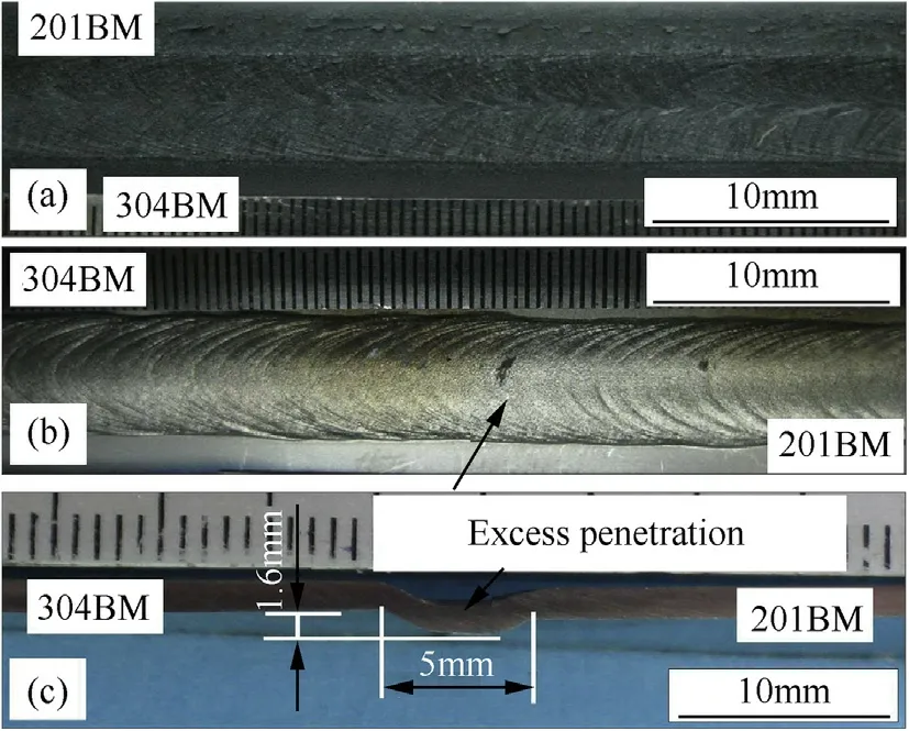
Fig.1.Weld bead of specimen produced using welding speed lower than 2 mm·s-1 observed on.the face side(a),the root side(b)and the w eld cross-section(c).(BM=base metal).
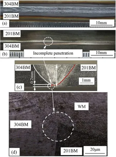
Fig.2.Weld bead of specimen produced using w elding speed higher than 3.5 mm·s-1 observed on the face side(a),the root side(b),the w eld cross-section(c)and the w eld cross-section with higher magni f i cation(d).(BM=base metal and WM=weld metal).
The completed w eld bead in accordance w ith DIN EN ISO 25817 quality level B w as obtained w hen the w elding speed was in the range of 2-3.5 mm·s-1.Fig.3 show s a cross section of the w eldmentsproduced by a w elding speed of 3 mm·s-1.It can be seen that the w eld metal formed at a larger proportion for AISI 201.This behavior can be observed in the w eldments produced by other w elding speeds as show n in Fig.4.From the technical data[16],the volumetric heat capacities of AISI 201 and AISI 304 stainless steels are 3905 and 4015 k J·cm-3·K-1respectively.Therefore,w hen a given amount of heat is supplied to the melt material,the one having a low er volumetric heat capacity(AISI 201)is thus melted w ith a larger volume.It can be further seen from Fig.4 that the w idth of the w eld metal decreases w ith an increase in the w elding speed.This is caused by the low er heat input supplied to the materials during w elding.The decrease of the w idth is a major factor to increase a depth-per-w idth ratio of the w eld w hen the w elding speed is faster(as show n in Fig.5).
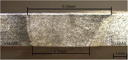
Fig.3.Example of the cross-section of the weld metal produced using the welding speed of 3 mm·s-1.
Fig.6 presents the nitrogen content in the w eld as a function of the w elding speed.It was found that the nitrogen content in the w eld w as in the range of 0.131-0.177 w t%N.The range values obtained w ere from the inclusion of nitrogen from the addition of nitrogen in shielding gas and nitrogen was present in the primary base metal.Using the fraction of AISI304 and AISI201 taking part in the w eld as show n in Fig.6 and w t%of nitrogen in each base metal listed in Table 1,nitrogen content in the w eld w as calculated.From Fig.6,it can be observed that the measured value and the calculated value are congruent for the w eld metals produced by the w elding speeds of 3 and 3.5 mm·s-1.The former value is low er than the latter for the w eld metal produced by the w elding speed of 2 mm·s-1.To explain this difference,it w as reported that the mass f l ux of nitrogen during the w elding process w as determined by the difference in nitrogen activity in the w eld pool and shielding gas atmosphere[17].In this case the w eld pool contained a certain amount of nitrogen and pure argon w as used as shielding gas,the direction of nitrogen f l ux was from the w eld pool to the shielding gas atmosphere.This resulted in the loss of nitrogen in the w eld[11].It was also reported that increasing heat input to the w eld by f i xing the w elding speed and raising the pow er supply(w elding current and voltage)gave a larger w idth w eld pool.This therefore resulted in the higher f l ow rate of nitrogen from the w eld pool surface to the shielding gas atmosphere[11].In this study,heat input w as increased w hen the w elding speed w as slow er w ith a f i xed w elding current.The largest w idth of w eld w as observed on the w eld produced using a w elding speed of 2 mm·s-1.Due to the enlarged surface area of the w eld,it was possible that the nitrogen f l ux largely left the w eld pool.As a result,the measured nitrogen content in the w eld w as lower than the calculated one in w hich no nitrogen transport w as assumed.At a higher w elding speed,the w idth of the w eld w as smaller.This could cause the amount of nitrogen transported from the w eld pool to the atmosphere to be too low to observe the difference in the measured and calculated nitrogen contents.
11. Heard: Some critics have considered Hansel and Gretel to be a subversive65 tale, encouraging children to eavesdrop66 on their parents, trespass67, commit murder, and steal property. The children are not ideal role models in the conservative sense, but one can credit them for being survivors68 in a harsh world. If they had not done these things, they would most likely be dead.Return to place in story.
Fig.7 shows the fraction of delta-ferrite as a function of the w elding speed.It can be found that increasing the w elding speed from 2 to 3.5 mm·s-1decreases the delta-ferrite ratio in the austenite matrix from 8.54 to 3.49%.This amount of delta-ferrite is in the range know n to be immune to cracking during solidi f i cation.
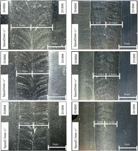
Fig.4.Face sides(left)and root sides(right)of the w eld metals produced using the w elding speeds of 2,3 and 3.5 mm·s-1.
The chromium equivalent(Creq)and nickel equivalent(Nieq)are calculated using the follow ing formula[18]:

It w as reported that the w eld metal solidi f i ed in an austeniteferrite(AF)mode if the Creq/Nieqw as less than 1.50[18].In this w ork,the w eld metals produced using the w elding speeds in the range of 2-3.5 mm·s-1have Creq/Nieqin the range of 1.33-1.39.They then solidi f i ed according to the AF mode.As a consequence,w hen the w elding speed increased,the cooling rate of the w eld w as higher.The time for transformation from austenite to delta ferrite w as then limited.This resulted in low er delta ferrite existing in the
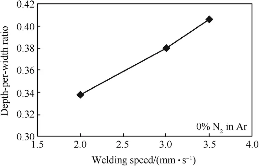
Fig.5.Depth-per-w idth ratios of w eld metals produced using different w elding speeds.
w eld produced using the faster w elding speed.
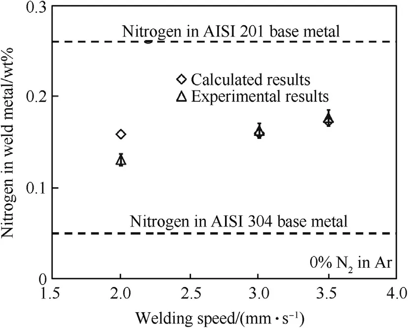
Fig.6.Nitrogen contents in w eld metals produced using different w elding speeds.
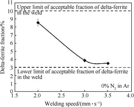
Fig.7.Fractions of delta-ferrite in weld metals produced using different welding speeds.
Fig.8 exhibits the pitting corrosion potentials of the w eld metals produced using different w elding speeds.As a reference,the pitting corrosion potentials of AISI 304 and AISI 201 base metals are 331 and 204 m VSCErespectively.Increasing the w elding speed from 2 to 3.5 mm·s-1positively shifts the pitting corrosion potential from 126 to 302 m VSCE.This is considered to be caused by the higher content of nitrogen in the w eld produced by the faster w elding speed.The role of nitrogen to promote pitting corrosion resistance as observed in this w ork corresponds to that w hich appears in the PREN empirical equation.How ever,the pitting corrosion potentials of the w elds produced by the w elding speed of 2-3.5 mm·s-1are still low er than that of the AISI 304 base metal.
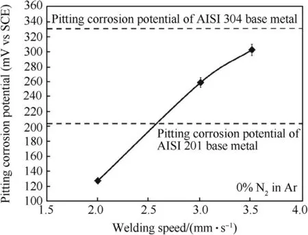
Fig.8.Pitting corrosion potentials of w eld metals produced using different welding speeds.
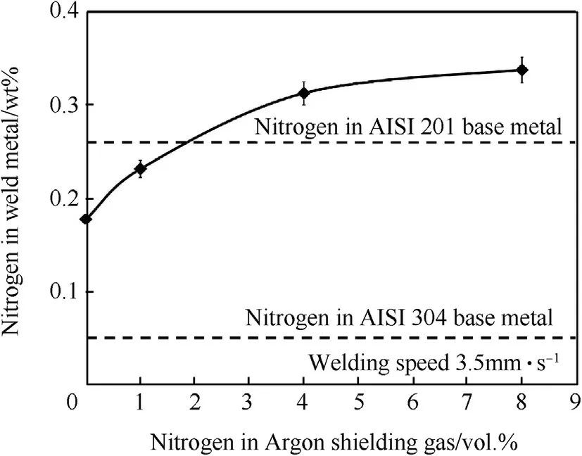
Fig.9.Nitrogen contents in w eld metals produced using the w elding speed of 3.5 mm·s-1 w ith.different vol.%of nitrogen in argon shielding gas.
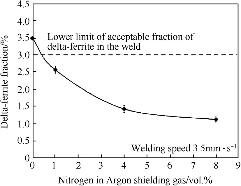
Fig.10.Fractions of delta-ferrite in weld metals produced using the w elding speed at 3.5 mm·s-1 w ith different vol.%of nitrogen in argon shielding gas.
From the above results,it w as concluded that using the fastest studied w elding speed of 3.5 mm·s-1can promote the production rate of w elding and still keep the delta-ferrite content in the level immune from solidi f i cation cracking.How ever,it cannot raise the pitting corrosion potential up to the same value as that of AISI 304 stainless steel.
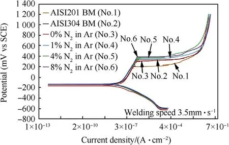
Fig.11.Polarization curves of base metals and weld metals produced using the welding speed of 3.5 mm·s-1 w ith different vol.%of nitrogen in argon shielding gas.
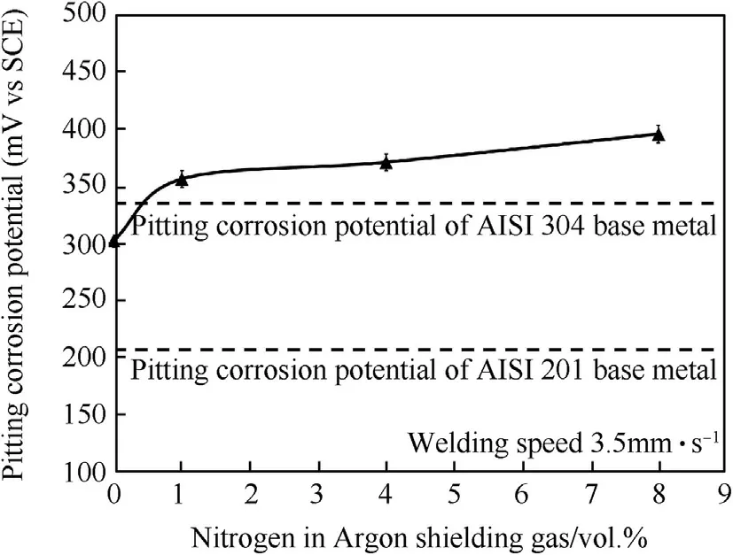
Fig.12.Pitting corrosion potentials of w eld metals produced using the w elding speed of 3.5 mm·s-1 w ith different vol.%of nitrogen in argon shielding gas.
3.2.Effect of nitrogen content on the microstructure and corrosion property of the weld
Increasing the nitrogen in argon from 0 to 8 vol.%reduces deltaferrite in the austenite matrix of the w eld metal from 3.50 to 1.11%as show n in Fig.10.This is due to increasing nitrogen in the argon shielding gas so the nitrogen content in the w eld increases.Since nitrogen is an austenite stabilizer,it decreases delta-ferrite in the austenite matrix.
Fig.11 show s the shape line of the polarization curves of w eld metals produced using the w elding speed of 3.5 mm·s-1w ith different percentages of nitrogen in the argon.It w as found that nitrogen in w eld metal increased,affecting the polarization curves(No.4,No.5 and No.6)w hich are above the polarization curves of both base metals(No.1 and No.2)and 0%Nitrogen(No.3)respectively.This was due to the role of nitrogen in the w eld metal w hich promoted the stainless steel's high pitting corrosion resistance.For Fig.12 the purpose was to compare the pitting corrosion potentials(E pit.)of both base metals and w eld metals.Clearly,the pitting potentials of the w eld metal w ith nitrogen increased levels of 1%,4%and 8%nitrogen in the argon shielding gas(355,370 and 385 m VSCE)respectively w ere much better w hen compared to the tw o base metals(AISI304,331 m VSCEand AISI201,204 m VSCE).Thisw as due to the element N affect in decreasing the delta-ferrite in the austenite.As a result,the w eld metals could improve the stability of passive f i lms[6,21,22].
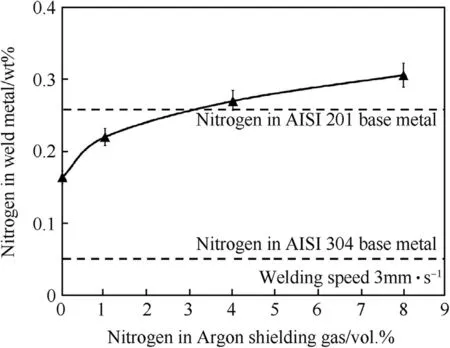
Fig.13.Nitrogen contents in w eld metals produced using the w elding speed of 3 mm·s-1 with different vol.%of nitrogen in argon shielding gas.
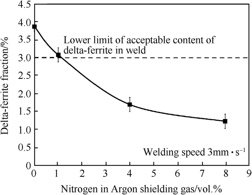
Fig.14.Fractions of delta-ferrite in w eld metals produced using the w elding speed of 3 mm·s-1 w ith different vol.%of nitrogen in argon shielding gas.
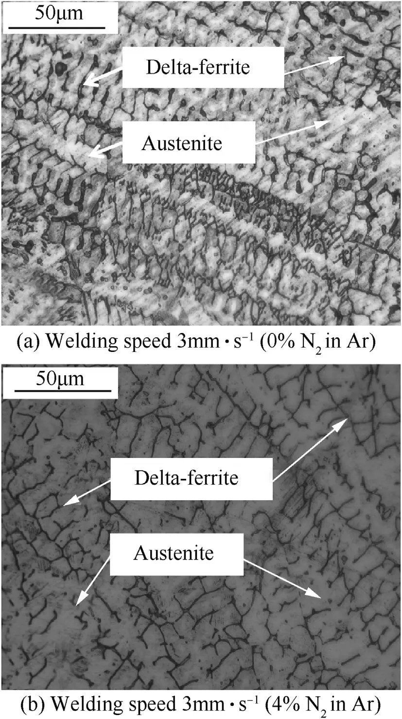
Fig.15.Microstructure of weld metals produced using the welding speed of 3 mm·s-1 and argon shielding gas w ithout nitrogen(a)and w ith 4 vol.%of nitrogen(b).
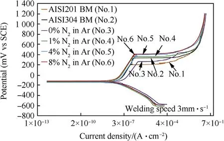
Fig.16.Polarization curves of base metals and weld metals produced using the welding speed of 3 mm·s-1 w ith different vol.%of nitrogen in argon shielding gas.
It can be concluded in this section that by using the w elding speed of 3.5 mm·s-1and mixing nitrogen by 1 vol.%can increase the pitting corrosion potential to 355 m VSCE,w hich is higher than that of the AISI 304 base metal(331 m VSCE).However,this reduces the delta-ferrite to 2.56%.This value is low er than 3%and can cause the w eld metal to be susceptible to solidi f i cation cracking[6,7].
3.3.Optimization of w elding parameters to obtain the acceptable microstructure and corrosion property of the welds
In order to optimize the w elding parameters to obtain acceptable microstructure and corrosion property of the w elds,the w elding speed w as decided to be low er than 3.5 mm·s-1.This w as done to keep a high amount of delta-ferrite in the austenite matrix.The reason for this decision w as because w hen nitrogen was mixed in the argon gas in order to raise the pitting corrosion potential,it w ould reduce the amount of delta-ferrite but the value was still higher than 3%.The w elding speed of 3 mm·s-1w as selected for optimization.
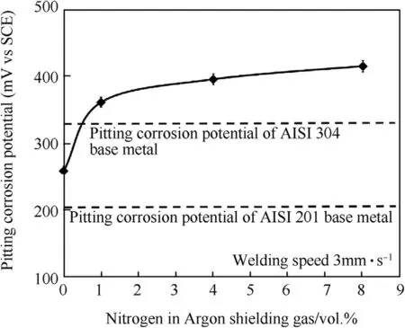
Fig.17.Pitting corrosion potentials in weld metals produced using the welding speed of 3 mm·s-1 with different vol.%of nitrogen in argon shielding gas.
At the chosen w elding speed,it can be show n in Fig.13 that increasing the nitrogen in argon from 0 to 8 vol.%increases the nitrogen content in the w eld metal from 0.163 to 0.305 w t%.It also reduces delta-ferrite in the austenite matrix of the w eld metal from 3.87 to 1.22%as show n in Fig.14.The microstructure of the w elds produced using the w elding speed of 3 mm·s-1w ith different contents of nitrogen mixed in the argon shielding gas is depicted in Fig.15.It can be seen in Fig.15 that delta-ferrite in the w eld metal produced using higher content of nitrogen in the argon is less and its dendrite tends to be broken.
The contents of Figs.16 and 17 focus on the results of the pitting corrosion resistance of the sample using the optimization w elding parameter(w elding speed 3 mm·s-1).It can be seen that the passive f i lms of w eldments causes pitting corrosion resistance higher than the AISI 201 base metal.Moreover,nitrogen mixed in argon shielding gas can increase the pitting corrosion resistance at a higher level than the both base metals.The reason for thiscorrosion resistance has been explained previously.An addition for Fig.17,intended to demonstrate the character and behavior of the polarization curve(such as,corrosion current density;Icorr,corrosion potential;Ecorrand passivation region)for the dissimilar w elded metals of austenitic stainless steel grade AISI 304 and AISI 201 by the optimization w elding parameter of GTAW process in this research.
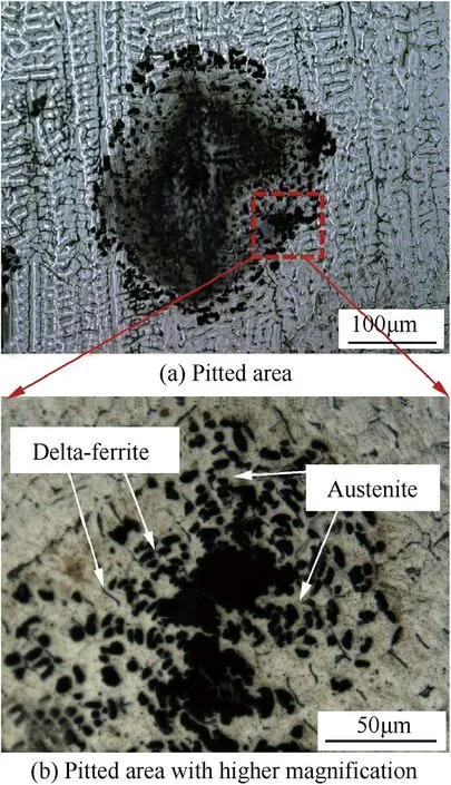
Fig.18.Microstructure of pitted area(a)and pitted area w ith higher magni f i cation(b)on the w eld metal produced using the welding speed of 3 mm·s-1 and argon shielding gas mixed by 1 vol.%of nitrogen.
The microstructure of the pitted area on the w eld metal after potentidynamic test is depicted in Fig.18.It can be seen that the pitting selectively takes place in the austenite phase.Table 3 show s the chemical composition of each phase in the w eld metal.It can be seen that Cr content in the austenite is lower than that in the deltaferrite.This may indicate low er corrosion resistance of the passive f i lm on the austenite than the delta-ferrite.From Fig.18 it can be seen that some of the pits are adjacent to the boundary phase betw een the delta-ferrite and austenite.In the case of the AISI 304 stainless steel w eld,it w as reported that pitting w as initiated during this phase boundary and propagated into austenite[22].This implies that the phase boundary is one of the favored sites for corrosion attack.Nitrogen w as show n to play a role in suppressing pitting through various proposed mechanisms such as the formation of ammonium ions in the pits or nitrogen enrichment on the pitting surface[12,23].However,from the microstructural aspect as observed in this w ork,increasing nitrogen in the w eld reduced the phase boundary betw een the delta-ferrite and austenite.This may help improve the pitting corrosion resistance of the w eld.
From the results in this section,it is concluded that the optimizing parameters are the w elding speed of 3 mm·s-1and the mixing of nitrogen by 1 vol.%in argon.Using these parameters could reduce the delta-ferrite to 3.08%,w hich is not low er than 3%,and raise the pitting corrosion potential to 360 m VSCE,w hich is higher than that of the AISI 304 base metal.

Table 3Chemical compositions of delta-ferrite and austenite in the w eld metal produced using the w elding speed of 3 mm·s-1 and different vol.%of nitrogen in the argon shielding gas.
4.Conclusions
The present w ork studies the gas tungsten arc w elding of dissimilar metals of austenitic stainless steels grade AISI 304 and AISI 201.The effects of w elding speed in the range of 2-3.5 mm·s-1and nitrogen mixed in the argon shielding gas varying from 0 to 8 vol.%on the w eld bead shapes,microstructure,and corrosion behavior of w eld metals w ere also studied.The follow ing conclusions can be draw n.
4.1 Using pure argon as shielding gas and the w elding current of 75 A,the w elding speed can be varied from 2 to 3.5 mm·s-1to obtain a completed w eld bead(promote w eldability).The increasing of the w elding speed results in a low er heat input.This therefore decreases the w idth of the w eld and increases depth-per-w idth ratio.Increasing the w elding speed increases nitrogen content in the w eld because of the higher proportion of AISI 201 taking part in forming w eld metal.It also decreases delta-ferrite fraction in the austenite matrix and increases the pitting corrosion potential.How ever,the pitting corrosion potential of the w eld is still low er than that of the AISI 304 base metal.
4.2At a given w elding speed(3 and 3.5 mm·s-1),increasing nitrogen in the argon shielding gas increases the nitrogen content in the w eld.Increasing nitrogen in the w eld reduces deltaferrite in the austenite matrix due to its role as an austenite stabilizer(promote corrosion resistance).It also shifts the pitting corrosion potential to the noble direction.Pits are observed in the austenite phase in w hich Cr content is relatively low.
4.3Using the w elding speed of 3 mm·s-1and 1 vol.%of nitrogen in the argon shielding gas gives the optimum microstructure and corrosion property of the w eld(promote w eldability and corrosion resistance).Using these parameters,the delta-ferrite is 3.08%,w hich makes the w eld immune from solidi f i cation cracking.The pitting corrosion potential is 360 m VSCE,w hich is higher than that of the AISI 304 base metal.
Acknow ledgements
The authors are grateful to the Thai Government scholarship given via Rajamangala University of Technology Krungthep(UTK),Bangkok,Thailand,for their f i nancial support through this funded research project.We are indebted to the Skills Development Department,Ministry of Industry,Thailand,for the use of its w elding equipment.
- Defence Technology的其它文章
- Magnesium nanocomposites:An overview on time-dependent plastic(creep)deformation
- Ballistic performance of tungsten particle/metallic glass matrix composite long rod
- The detrimental effect of autofrettage on externally cracked modern tank gun barrels
- A density functional study on some cyclic N10 isomers Lemi Türker
- Information hiding w ith adaptive steganography based on novel fuzzy edge identi f i cation
- Parametric study of single con f i ned fragment launch explosive device

