
Computational investigation of hydraulic performance variation with geometry in gabion stepped spillways
2019-05-18 07:37:34DominicReeveAliAdelZuhairaHarshinieKarunarathna
Water Science and Engineering 2019年1期
Dominic E.Reeve*,Ali Adel Zuhaira,Harshinie Karunarathna
College of Engineering,Swansea University,Swansea SA2 8PP,UK
Received 18 May 2018;accepted 3 January 2019
Available online 8 April 2019
Abstract Over recent years,there has been a clear increase in the frequency of reported f looding events around the world.Gabion structures offer one meansof f lood mitigation in dam spillways.Thesetypesof structuresprovidean additional challenge to thecomputational modeller in that f low through the porous gabions must be simulated.We have used a computational model to investigate the f low over gabion stepped spillways.The model was f irst validated against published experimental results.Then,gabion stepped spillways with four different step geometries were tested under the same conditions in order to facilitate inter-comparisons and to choose thebest option in terms of energy dissipation.The results show that normal gabion steps can dissipate more energy than overlap,inclined,and pooled steps.An intensive set of tests with varying slope,stone size,and porosity wereundertaken.Thelocation of theinception point and thewater depth at thispoint obtained from thisstudy werecompared with those from existing formulae.Two new empirical equations have been derived,on the basis of a regression analysis,to provide improved results for gabion stepped spillways.
Keywords:Computational modelling;Energy dissipation;Gabion stepped spillways;Inception point location;Skimming f low
1.Introduction
Spillways can be def ined as structures,located over dams,whose function is to release any excess water during the f looding seasons in order to reduce the probability of having an overtopping failure(Novak et al.,2001).Many materials can be used in the construction of spillways,including roller compact concrete and gabions.Each material has advantages and disadvantages(Boesand Hager,2003).Energy dissipation can be considered one of the main design elements of stepped spillways because the high energy of the f low can cause many problems at the toe of the structure,such as the formation of scour holes,which can lead to structural failure in spillway foundations.Also,overtopping damage can occur,which can cause signif icant problems for people in the surrounding areas(Novak et al.,2010).
Chanson(2002)has def ined two typesof f low over stepped spillways:non-aerated f low and aerated f low.Normally,nonaerated f low takes place along the upper steps of spillways where there is no air entrainment,while aerated f low can be observed along the lower steps where air entrainment occurs(e.g.Andre and Schleiss,2004;Chanson,1994,1995).For the samegeometry,when thedischargeincreases,thelength of the non-aerated zone also increases.Thus,the likelihood of generating cavitation will also increase.As noted by Husain et al.(2013),cavitation can be extremely damaging and even destroy spillways,leading to operational failure of the steps and spillways.The aerated zone can be determined by estimating thelocation of the inception point,which represents the endpoint for the non-aerated zone and the start of the aerated zone.The inception point is the location where the boundary layer intersects the free surface of the water(Chanson,1994,1996).Flow over stepped spillways can be classif ied into three hydraulic regimes:nappe f low,transition f low,and skimming f low(Zhang and Chanson,2016b).
Traditionally,spillways have been impermeable.However,the use of a permeable layer such as gabions offers a means to improve the hydraulic performance by enhancing energy dissipation.Gabions are containers that can be f illed with gravel,cobbles,stones,and rocks,depending on the purpose of construction.Since 1879,gabions have been used in China and Egypt.Gabionshave also been used for different purposessuch as riverbed protection,bank stabilization,and retaining walls.Thereare threedifferent typesof gabions:basket,mattress,and sack.All of these may be f illed with gravel and/or cobble materials(Zhang and Chanson,2014).The choice of gabion typedependsupon theapplication.For instance,basket gabions are commonly used for stability purposes and to protect river bedsand stream banks(Freeman and Fischenich,2000).A brief discussion of earlier studies conducted on gabion stepped spillways is provided below.
Gabions are one common construction element for spillways in the African Sahel(Peyras et al.,1992).Gabions have been used widely for water structures like small earth dams,retaining walls,intakes,and soil conservation work.Salmasi et al.(2012)stated that there are many benef its from using gabions,such as ease of construction,structural stability,f lexibility,and resistance to water load.The resistanceto water load is likely to be related to f low through porous media.Porosity can help thewater to drain faster and reduce thewater load behind the structure(Zhang and Chanson,2016a).Permeability is known to affect the f low properties of the free surface in many cases(Manes et al.,2009).It has been suggested that related f low mechanisms can play a vital role in increasing or decreasing friction factors,thereby affecting the shear penetration within the permeable bed,which can in turn affect the boundary layer.Hence,increasing the f low resistance may increase energy dissipation due to the momentum exchange between the surface and subsurface f lows.
Stephenson(1979)performed a study on energy dissipation over stepped gabions.Different conf igurationswere examined,such as stepped gabions with two to four steps and with four different slopes:1:1,1:2,1:3,and 2:3.The energy dissipation was calculated using the differences in depths between the areas upstream and downstream.The results showed that the relative energy dissipation ranged from 25%to 85%.They also showed that the energy dissipation increased as the number of steps increased to three,but then decreased as the number of steps increased further.Concerns about the ability of gabion steps to resist damage under high f lows were addressed by the experimental study of Peyras et al.(1992),who showed that gabion stepped weirscan withstand f loodsup to 3 m3/(m∙s)without any damage.Kells(1994)studied the energy dissipation over a gabion stepped weir as a function of the critical depth at and discharge over the crest.This experimental study used two downstream slopes of 1:1 and 1:2,and the main f inding was that 20%of the energy can be dissipated due to the through-f low.Moreover,no signif icant differences were noticed in the energy dissipation when the slopes changed.It is important to note that the number of the stepsin the previous studies affected the energy dissipation results more than the spillway slope.Therefore,more research is required to investigate the impact of the number of steps.
The sensitivity of the hydraulic performance to the characteristics of the material contained in gabions was investigated experimentally by Chinnarasri et al.(2008).They used three stone types:(1)crushed stone of about 25-35 mm in diameter;(2)rounded stone of about 25-35 mm in diameter;and(3)crushed stone of about 50-70 mm in diameter.The results showed that the energy dissipation ratios over gabion stepped weirs were greater than those over the corresponding impermeable stepped weirs by nearly 7%,10%,and 14%for weir slopes of 30°,45°,and 60°,respectively.Consequently,the outlet velocity was lower.Moreover,the results showed that both the stone size and stone shape had a small effect on the energy loss and f low velocity compared to the weir slope.Thepressure on thestep face of gabion stepped weirswasless than that on thehorizontal step dueto thedampening inf luence of f illed stones.The average pressure difference was approximately 29%.More recently,Wu¨thrich and Chanson(2014)carried out a laboratory study to investigate the hydraulic characteristics of f low,such as f low patterns,air-water f low properties,and energy dissipation over normal and gabion stepped spillways with a 1:2 slope and a 0.1-m step height.This study was conducted with a wide range of f low rates in order to investigate nappe,transition,and skimming f lows.They found that large velocities could be observed at the downstream end of gabion stepped spillways,as well as low rates of energy dissipation over gabion steps in comparison to smooth impervious steps.It can be concluded that there are many parameters with impacts on the performance of gabion stepped spillways,such as the size of stones,water f low conditions,and the air-f low entrainment.However,at present,there is no clear picture of which of these parameters has the strongest inf luence on the eff iciency of gabion stepped spillways.Thus,further investigations are needed to determine the essential controlling factors.
It is well established that stepped spillways(gabion or other)have an advantage over non-stepped spillways in terms of reducing cavitation damage due to air entrainment and by improving energy dissipation performance(Husain,2013).Although there is a well-developed understanding of the performance of normal stepped spillways,the same level of understanding has not been developed for gabion stepped chutes with more complex designs.Moreover,even though stepped spillways have been extensively studied using computational models,detailed numerical modelling studies on gabion stepped spillways have not been recorded.Also,gabion porosity and gabion stone size,both of which affect the f low,need to be investigated in detail in order to demonstrate their impacts on other important parameters,such asthe location of the inception point.Finally,f inding an optimum gabion stepped spillway design can improve performance and offer an alternative for stepped spillway construction.
In this study,we used a computational model as a numerical f lume to investigate the performance of gabion stepped spillways under a range of conditions that covered spillway slope,step geometry,step height,gabion stone size,and porosity.In Section 2 details of the computational model are described together with some validation results.In Section 3,results of the computations along with discussion of their implications for hydraulic performance are presented,and the computational resultsobtained in thisstudy arecompared with those of some existing empirical equations for estimation of the location of the inception point and water depth at that point.Finally,two new equations are proposed for gabion stepped spillways.
2.Problem formulation and numerical model
2.1.Problem formulation
There are many issues that need to be addressed in the selection of anumerical model that can beused to simulatethe f low over gabion stepped spillways(Fig.1)such asthemodel's capability to simulate the turbulent f low over the porous media,the treatment of the interface between the f luid layer and porous medium,and the treatment of the free surface.Sincethisstudy mainly aimed to investigate the location of the inception point,many caseshavebeen tested in order to assess the inception point location under different f low conditions,step heights,and spillway slopes with wide ranges of gabion stone sizes and porosity.The inception point determines the endpoint of the non-aerated zone;this point is immediately followed by the aerated zone.Air entrainment is one of the most important factorsthat can protect thehydraulic structures from cavitation damage due to the air-water f low.The inception point is def ined as the point where the boundary layer intersects the free surface.The boundary layer thickness can be predicted by determining the point where the velocity is 99%of its maximum value in the velocity distribution prof ile at any particular location along the spillway(Schlichting,1979;Husain et al.,2013).Thus,the water depth at that point,measured perpendicular to the pseudo-bottom,can be obtained directly from the computed valuesof the free surface.
2.2.Numerical model
As the f low in this study contained elements that were subcritical,supercritical,and highly turbulent,weused acode that solved the Reynolds-averaged Navier-Stokes(RANS)equations with a turbulence sub-model.The code chosen was NEWFLUME,described in detail by Lin and Xu(2006),which solves the RANS equations in two dimensions(2DV).For completeness'sake,we provide a brief description of the equations and solution technique here.The equations for f low outside the porous media are

Fig.1.Turbulent f low over gabion stepped spillway.
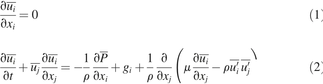
where
uiis the mean velocity in the xidirection(i=1 means the horizontal direction,and i=2 means the vertical direction)(m/s),t is time(s),P is the mean pressure(kN/m2),ρis the f luid density(kg/m3),giis the gravitational acceleration in the xdirection(m/s2),μisthemolecular viscosity(kg/(m∙s)),and represents the Reynolds stress(kN/m2).The mean viscous stress is written as

The Reynolds stress was calculated using a nonlinear eddy viscosity model.This model used mean velocity,turbulence kinematic energy(k),and dissipation rate of turbulence(3).The k-3 transport equation was used to calculate k and 3(Lin and Xu,2006).
The mean f low in the porous media is governed by


The coeff icientsin Eqs.(4)and(5)aregiven by Lin and Xu(2006)as where D50isthemedian diameter of gravel f illing thegabions,γP=0.34,α=200,β=1.1,and,with T being a calibration parameter.
Free surface tracking was achieved through the application of the volume of f luid(VOF)method,which was originally established by Hirt and Nichols(1981)and subsequently adjusted by Kotheet al.(1991).A f inite difference method was employed to approximate all partial differential equations.The calculation of the mean f low outside the porous media was performed with the Navier-Stokes equation solver that was developed by Kotheet al.(1991).Thismethod used atwo-step projection to solve the momentum equations.Initially the velocity was estimated without the pressure gradient term.In the second step the velocity was corrected using the updated pressure f ield,which was determined from the Poisson pressure equation.The governing equations for the f low through the porous media had the same structure as the RANS equations.However,Reynolds stresses were replaced by linear and nonlinear friction terms.The two-step projection technique was also used for the f low calculation through the porous media.On the interfacebetween the porous media and outside f low,the continuity of the pressure and velocity was satisf ied.The central difference method was used to discretize all the pressure and stress gradients in the projection method.The upwind scheme was combined with the central difference method to discretize the advection terms for the k-3 transport equation.
2.3.Sample validation
The capability of NEWFLUME was demonstrated by Lin and Xu(2006)through a series of case studies encompassing a wide range of turbulent free surface f lows,covering coastal and ocean engineering(e.g.,breaking wave interaction with a seawall and wave forces on a submerged pipeline),hydraulic engineering(e.g.,dam break f low and hydraulic jump),and environmental modelling(e.g.,jets and pollutant transport).
As an additional validation exercise for the case of f low down a gabion stepped spillway,we compared the model results against the experimental work of Wu¨thrich and Chanson(2014).Their test section consisted of a broad crested weir with a length of 1.01 m and a height of 1.0 m,followed by ten identical impervious steps with a height of 0.1 m and a length of 0.2 m.Gabion steps were installed over the impervious steps,which were made from marine plywood,with a 0.1-m height and a 0.3-m length.Gravel inside the gabions had a D50of 0.01 m.The porosity ranged from 0.35 to 0.40.
The same experimental conditions were established in the numerical model.The mesh sizes were set to 0.010 m and 0.005 m in the x-and y-directions,respectively.The initial water depth was set to 1.4 m in order to achieve a required discharge.The discharge was calculated by determining the critical section over thebroad crested weir.Thecritical section was determined by testing directly,from the model output,the value of the Froude number,Fr,with Fr=where q is the discharge per unit width,and h is the water depth.The critical section occurred where Fr=1.To ensure numerical stability,the initial time step was set to 0.001 s and the simulated period was 24 s.As in the laboratory experiments,all of the boundaries were closed except the right boundary,which was open.It is important to mention that dam break conditions were used in the numerical model rather than the steady stateused in the experiments of Wu¨thrich and Chanson(2014).Dam break conditions were used in order to capture different values of discharge at different times and also to observe the development of the f low pattern,such as nappe f low,transient f low,and skimming f low,over thegabion boxes.In the numerical model,dam break conditions were recreated with the f luid at rest and an impermeable barrier placed at x=9.0 m,as shown in Fig.2,in which velocity vectors are plotted at regular grid points to give an indication of the f luid layer,free surfaces are contoured in blue continuous lines,the outline of the impermeable dam is shown as black lines,and gabion steps are shown as red lines.This barrier was removed instantaneously at t=0 s and the f luid then moved under the force of gravity.
The porosity of gravel was set equal to 0.375,representing the average value used in the experimental study.The f luid was initially at rest.The volume of the upstream tank was 9.0 m×1.4 m per unit width.The barrier at x=9.0 m was removed instantaneously and the resulting f low was computed(Fig.2).The validation was conducted in terms of the location of the inception point.The velocity distribution over the outer edgeof the stepswasused to determine the inception point.As illustrated in Fig.3,the velocity prof ile over the steps in the non-aerated zone is quasi-parabolic with no quasi-uniform segment in the upper part of the f low prof ile.The physical meaningsof thevariablesin Fig.3 can befound in Section 3.3.
Results shown in Table 1 illustrate that the model was able to simulate the f low over the gabion steps and also to capture the location of the inception point in agreement with experimental results.Further details of the validation testing can be found in Zuhaira et al.(2017).
3.Results and discussion
3.1.Model set-up
In the numerical model,two arrangements were used to accommodate the spillway geometry variations described in Section 3.2 and to meet the requirement that the critical water depth be established over the weir crest.For the spillway with 0.06-m-high steps,theweir wasplaced at x=6.9 m,while for spillwayswith step heightsof 0.09 m and 0.12 m,the weir was placed at x=7.4 m.In all cases the length of the weir crest was set to 0.6 m.
The initial water depths were 1.58 m,1.70 m,and 1.80 m for spillways with step heights of 0.12 m,0.06 m,and 0.09 m,respectively,which ensured that the upstream tank contained suff icient water to achieve the required discharge and also to mitigate theeffectsof transients.The total simulation timewas set to 15.0 s for the 0.12-m step height,16.5 s for the 0.09-m step height,and 18.0 s for the 0.06-m step height.The time step was set at 0.0001 s to satisfy the stability criterion in all cases.The mesh sizes in the x-and y-directions were 0.010 m and 0.005 m,respectively for 0.09-m and 0.12-m step heights.However,for the 0.06-m step height,they were reduced to 0.0075 m in the x-direction and 0.0030 m in the y-direction,respectively.The model domain had closed boundaries except for the right-hand boundary,which was set as an open boundary to let the water exit the f lume.Overall,many cases of gabion stepped spillways were tested in the current study.Each step height(0.12,0.09,and 0.06 m)was examined individually with three spillway slopes(1:2,1:2.5,and 1:3).Then,for each of these nine spillway geometries,simulations were performed for four different gravel sizes and four different values of porosity.A step height of 0.12 m with a 1:2 spillway slope was chosen initially in order to test the selected gravel sizes and porosity.Comparisons were conducted for specif ic discharges at the skimming f low stage.
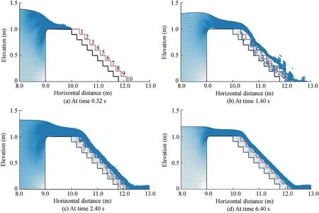
Fig.2.Flow over gabion stepped spillway at different times.
Parameter values of typical gravel were used to represent the porous media component.According to the standards,the minimum diameter of particles should begreater than 2 mm in order to consider them gravel(Wentworth,1922).Therefore,the minimum value for the gravel size in this study was set to 5 mm.The diameters of 10 mm,15 mm,and 20 mm were tested aswell.Theporosity of gravel normally rangesbetween 0.25 and 0.40.Therefore,values of 0.25,0.30,0.35,and 0.40 were tested in this study.
To summarize,a set of numerical experiments were conducted to compute the f low over gabion stepped spillways for a dam break case in which the step height,spillway slope,gravel diameter,gravel porosity,and gabion geometry varied individually.
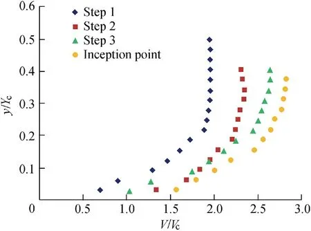
Fig.3.Velocity distribution over different steps in non-aerated zone.

Table 1 Comparison between inception point locations of experimental and numerical results.

Fig.4.Four different conf igurations of gabion steps considered in this study.
3.2.Different step geometries
The four different gabion step geometries,normal,overlap,inclined,and pooled,are shown in Fig.4 for the case in which thestep height was0.12 m.All theconf igurationsof thegabion steps were installed over impervious steps.The same initial conditions were applied in all conf igurationsin order to determine the differencesin termsof thetimeto establish skimming f low,thelocation of theinception point,and energy dissipation.
3.3.Energy dissipation
Energy dissipation is one of the most important parameters from the hydraulic design point of view.To investigate the energy dissipation for each of the gabion conf igurations,we applied Bernoulli's equation,following Husain(2013).The variables required to estimate the energy dissipation are described in Fig.5,where P is the pressure head at the top of the weir(m).The datum,or zero head line,is shown as a dashed horizontal line,and the total head is demonstrated by a full horizontal line at the top of the f igure.In brief,two points are required to determine the energy dissipation(ΔH).At the f irst point(a point under consideration in the non-aerated zone),the head H is calculated as follows:
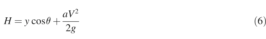
where y is the perpendicular depth of water over a pseudobottom(m),tanθis the spillway slope,a is the energy coeff icient(unitless),and V is the f luid velocity(m/s).

Fig.5.Two-dimensional schematic view of stepped spillway showing parametersrequired to estimate residual energy at outer edge of steps.
The second point is located upstream of the weir and the head is calculated as

where Y0is the f low depth above the horizontal surface of the step under consideration(m),and V0is the approach f low velocity(m/s).
Hence,as shown in Fig.5,the total energy dissipation with respect to the point under consideration is

The computational results of energy dissipation at x=9.44 m were 0.099,0.076,0.069,and 0.046 m2/s2for the spillways with normal,overlap,inclined,and pooled gabion steps,respectively.This demonstrates that for this situation normal gabion steps had the best performance in terms of energy dissipation,while pooled gabion steps exhibited the worst performance.To investigate this,further calculations of the turbulent kinetic energy(TKE)of the f low were made.TKE is the kinetic energy per unit mass of the turbulent f luctuation in the f low.It is generally accepted that,for spillway f low,the energy dissipation induced by turbulent eddies is greater than the energy loss due to internal and boundary frictions.Thus,there is a strong relation between the energy dissipation and TKE,and overall energy dissipation is prompted by creating turbulent f low(Husain,2013).
The TKE was computed directly from the instantaneous velocities over the whole domain(see Fig.6(a)).The plot shows that,from being initially at rest,the f luid gradually acceleratesdown thespillway,resulting in arisein TKEasthe discharge changes from nappe to transition to skimming f low.There are some f luctuations in TKE as skimming f low is established during the time between 2 s and 4 s after the dam break,and then TKE gradually decreases as the head in the upstream tank falls towards the level of the weir.
The results reveal that normal gabion steps generated greater amounts of TKE,by inference greater overall energy dissipation,than the other shapes.The f inding is in agreement with the calculated results of energy dissipation for different gabion geometries.For all the gabion geometries,there is a slight increase in TKE for 7.5 s<t<8.5 s,arising from an increase in the discharge at this time due to the ref lected transient in the upstream tank.Finally,as a further check,the turbulent energy dissipation rate,3,calculated directly from the k-3 equation,is shown in Fig.6(b),and conf irms that the turbulent kinetic energy and its dissipation rate have a similar morphology over time.
3.4.Inception point location
The computational results of the inception point location were 9.75,10.16,10.20,and 10.32 m from the downstream edge of the weir for the spillways with normal,overlap,inclined,and pooled gabion steps,respectively.Theresultsshow that the non-aerated zone for normal gabion steps was smaller than those for other types of gabion steps,while the longest non-aerated zone was observed for pooled gabion steps.Also,the results show that there was a small difference between overlap gabion steps and inclined gabion steps in terms of the inception point location.Normal gabion steps exhibited the best results in terms of energy dissipation and the location of inception point.
3.5.Sensitivities to slope,porosity,and gravel size
As the normal step conf iguration exhibited the best performance in terms of energy dissipation,discussion in this section is restricted to this case.Three different step heights and three different step widths for a given weir height were tested with thenumerical codeto investigatetheimpact of step conf iguration on the f low properties over gabion stepped spillways.Step widths were set to give spillway slopes of 1:2,1:2.5,and 1:3.The porosity of the gabion steps was varied from 0.25 to 0.40,while the gravel sizes were varied from 0.005 m to 0.020 m.The selection of these values provided wide-ranging physical characteristics likely to be encountered in real schemes in order to investigate the effectsof the gabion porosity,gabion gravel size,spillway slope,and step height on the f low characterization.
Fig.7 shows the effect of the step height on the location of the inception point.The calculations of the developing boundary layer thickness were carried out at the end of each step,in order to determine the location of the inception point.In the plot,the dots denote the top of the boundary layer at the end of each step,and the inception point occurs where the boundary layer meetsthefree surfacethat isshown asthe blue line.It is clear that step heights affect the location of the inception point and the length of the non-aerated zone.
The location of the inception point moves downslope as the discharge increases.In other words,the length of the nonaerated zone increases with the f low rate.This is most likely related to the discharge,as increasing discharges imply increasesin f low depth and/or velocity.Increasing thef low depth might increase the length of the boundary layer required to intersect the free surface prof ile.For a given slope and discharge,it isobserved that the location of theinception point moves to the upstream side towards the weir crest when the step height is increased(Fig.7).This can be attributed to the fact that large step heights can have a stronger impact on the location of the inception point than small step heights as the velocity of the overf lowing water is decelerated when it f lows over the outer step edgeand hitsthe horizontal face.However,this effect might be expected to decrease with lesser discharges.
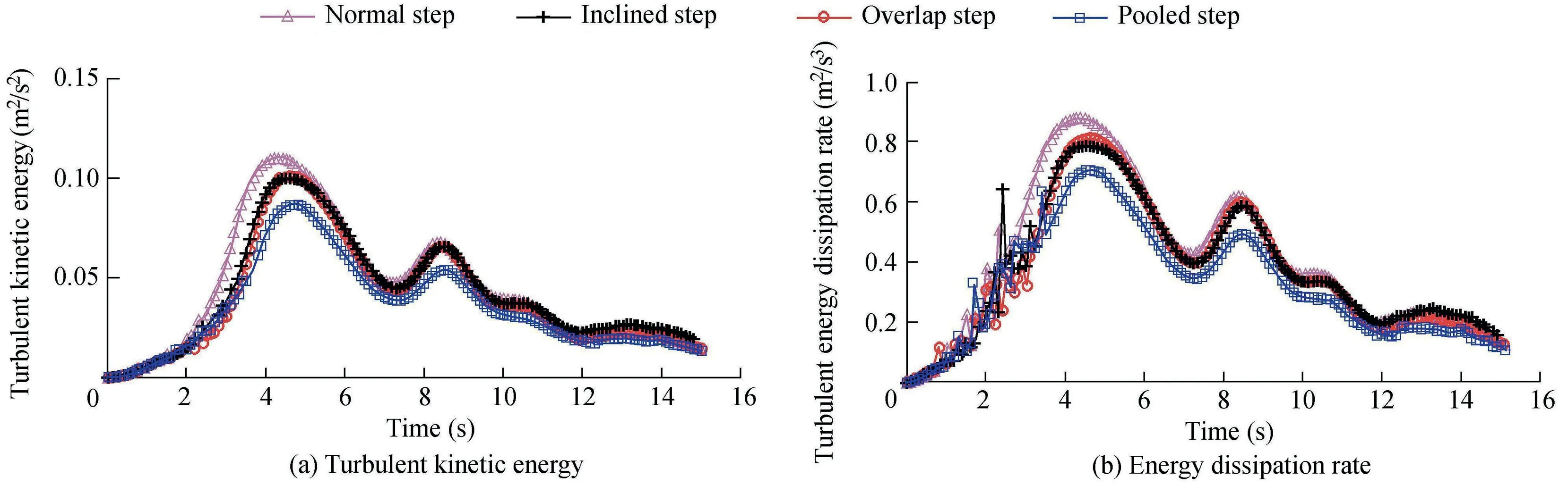
Fig.6.Turbulent kinetic energy and its dissipation rate for different gabion geometries.

Fig.7.Estimation of inception point location for spillway slope of 1:2 and unit discharge equal to 0.2 m2/s.
In order to investigatetheeffect of thespillway slope on the location of the inception point and the length of the nonaerated zone,three different slopes(1:2,1:2.5,and 1:3)were tested with three different step heights(0.06,0.09,and 0.12 m).Three values of discharge,0.25,0.20,and 0.15 m2/s,were used for comparison purposes to explore how the discharge inf luences the results.
The general trend of the numerical results reveals that the location of the inception point may move upslope when the spillway slope becomes steeper.Therefore,it can be concluded that the length of the non-aerated zone has a reciprocal dependence on the spillway slope(Fig.8).In other words,a shorter length of the non-aerated zone will be expected for a steep spillway slope in comparison with a f lat spillway slope.This can be explained by the fact that the longitudinal velocity over steep slopes is higher than that over f lat slopes.Therefore,the f low depth will be lower for steep spillway slopes.Thisislikely to accelerate the development of the boundary layer and its expansion throughout the water column to meet the free surface.All of the previous observations agree with the experimental observation of Andre(2004)who conducted a study on normal stepped spillways.However,for gabion stepped spillways,this kind of relation has not been reported before.
Furthermore,the results show that both porosity and gravel size can have a signif icant impact on the location of the inception point.The computational results for high discharges reveal a general trend that,when thegravel size decreases,the location of the inception point moves upslope towards the weir.Thus,the length of the non-aerated zone will be shorter.A relationship between porosity,gravel size,and the length of the non-aerated zone seems stronger for larger discharges.To quantify the relationship,we describe a nonlinear multiple regression analysis in the next section to determine the strength and robustness of the putative relationships discussed above.
3.6.Predictive formulae
Previous studies such as Chanson(1996),Carosi and Chanson(2008),Meireles and Matos(2009),Hunt and Kadavy(2011),and Husain et al.(2013)have developed nonlinear multiple regression equations to f it the results obtained in their work for normal stepped spillwaysto predict the length of the non-aerated zone and the water depth at the inception point.Our computational results were compared with the results from those nonlinear multiple regression equations.Some def iciencies were observed which provided the motivation to develop modif ied formulae appropriate for gabion stepped spillways.For this purpose,the values of the length of the non-aerated zone,Li,and the corresponding valuesof theroughness Froude number,F*,collected from the cases described above were used to obtain the following relationship:

Fig.8.Estimation of inception point location for 0.06-m step height and unit discharge equal to 0.15 m2/s.

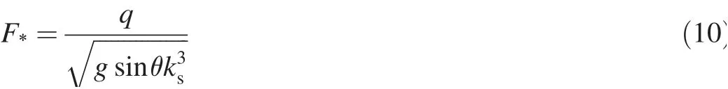
where ksis the roughness,which is calculated as hscosθ,and hsis the step height.The roughness Froude number can be calculated from
In developing Eq.(9),we started with Chanson's(1994)equation for normal stepped spillways and included extra terms related to gabion boxes.The coeff icients of Eq.(9)were estimated using an iterative least squares estimation routine available in MATLAB.For the f itting,results from the computational model were split into two groups.The f irst group,which contained around 80%of the data,was used to f ind thecoeff icients of the equation.The remaining data(20%)were used to test the equation.All the data were selected randomly and were restricted to cases in which the step geometry was normal.The coeff icient of determination,R2,was used to measurehow well theregression lineapproximated the data.If the value of R2approached 1.00,then the regression line was considered to have provided a perfect representation of the data.Fig.9 shows that the value of R2for Eq.(9)is 0.9057,with a correlation factor of 0.952,which gives an indication that the formula describes the data well.
The regression analysis indicates that the porosity term has a negative power sign,which reveals a reciprocal relationship between porosity and the length of the non-aerated zone.Also,a small value for the power,which is-0.2831,suggests that porosity has less impact on the length of the non-aerated zone than either F*or the spillway slope.The positiveexponent for the gravel size shows a direct relationship between the gravel size and the length of the non-aerated zone,and again the value isquite small,which means that the dependence of Lion the gravel size is not very strong.

Fig.9.Data test against Eq.(9).
A further comparison was conducted against different empirical equations for normal stepped spillways,including(1)Li/ks=9.8(sinθ)0.08F0.71*from Chanson(1994),(2)Li/ks=1.05+5.11F*from Carosi and Chanson(2008),(3)Li/ks=5.25F0.95*from Meireles and Matos(2009),(4)Li/ks=6.1(sinθ)0.08F0.86*from Hunt and Kadavy(2011),and(5)Li/ks=5.19F0.89*from Hunt and Kadavy(2013).The objective of this comparison was to assess whether the empirical equations established for normal stepped spillways could be used to f ind the location of the inception point over gabion stepped spillways.
Comparisons of the predictions from these f ive formulae against the computational results of the present study are shown in Fig.10.It is evident that all the formulae overestimate the location of the inception point in comparison with the computational results of the present study,with the formula from Hunt and Kadavy(2013)showing the closest agreement.
It is important to mention that the formulae from these earlier studies were derived from experimental results based on physical models of normal stepped spillways.However,the formula of the current study is based on the results of computational modelling.The results in Fig.10 show that using gabion boxes increased the roughness of the spillway surface and therefore accelerated the growth of the boundary layer thickness.Hence,the length of the non-aerated zone was reduced.Using the formulae for normal stepped spillways to predict the non-aerated length over gabion stepped spillways will likely givean overestimation,leading to very conservative designs.
The computational results were used to develop another equation for estimation of the water depth at the inception point for gabion stepped spillways.The expression is given as follows:
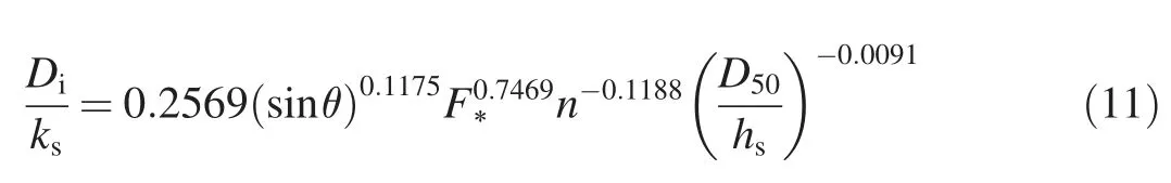
where Diis the water depth at the inception point.Using the same procedure as that for development of Eq.(9),the values of R2and the correlation factor for Eq.(11)were obtained as 0.9413 and 0.97,respectively.

Fig.10.Comparison of computational results against published formulae for length of non-aerated zone.

Fig.11.Comparison of computational results against published formulae for water depth at inception point.
The results of Eq.(11)were compared with those of empirical formulae,i.e.,0.04]F0.64*from Chanson(1994)and.68from Meireles and Matos(2009),as shown in Fig.11.Both of the empirical formulaeweredeveloped for normal stepped spillways,not for gabion stepped spillways.As can be seen in Fig.11,the formula from Chanson(1994)consistently overestimates the water depth,while the formula of Meireles and Matos(2009)slightly underestimates the water depth,in comparison with the computational results of the present study.
It should be noted that both Eqs.(9)and(11)are valid for gabion stepped spillways.Both of the equationswere obtained from the computational results for different step heights of 0.06,0.09,and 0.12 m(0.832≤Yc/hs≤3.080)with different spillway slopes of 1:2,1:2.5,and 1:3.Moreover,these equations were applicable for porosity ranging from 0.25 to 0.40 and D50in the range of 0.005-0.020 m.The maximum discharge used was 0.25 m2/s.As ever with empirically derived formulae,application outside the parameter ranges used to develop the formulae is not recommended unless further tests are performed.
4.Conclusions
The hydraulic performance of different gabion stepped spillways has been investigated with a state-of-the-art numerical model based on solving the RANSequations.To test the capability of the numerical model,a validation was conducted using the experimental data of Wu¨thrich and Chanson(2014).Four different geometries of gabion steps were investigated to compare the results in terms of energy dissipation and the location of the inception point.These four geometries were normal gabion steps,overlap gabion steps,inclined gabion steps,and pooled gabion steps.
The resultsshowed different hydraulic characteristics for the four typesof gabion stepsin termsof energy dissipation and the inception point location.The normal gabion step geometry showed the best performance for theenergy dissipation and the location of the inception point.The length of the non-aerated zone was explored for a range of step heights,spillway slopes,gabion porosity,and gabion gravel sizes using a computational model.The results showed that the length of the non-aerated zone increased with decreasing step height and also with decreasing spillway slope.A weaker dependence of the location of the inception point on both porosity and gravel size wasfound.
Two empirical equations were derived on the basis of the regression analysis to estimate the location of the inception point and the water depth.These two equations were compared with other formulae developed on the basis of physical experiments for the f low over normal stepped spillways.The results showed that using gabion boxes would increase the roughness of the spillway surface and therefore accelerate the growth of the boundary layer thickness.It would further reduce the length of the non-aerated zone.Overall,using porous media over concrete steps,as simulated in this study,would be expected to reduce the non-aerated length and thus reduce the danger of cavitation damage over the steps.
 Water Science and Engineering2019年1期
- Water Science and Engineering的其它文章
- Application of power law to vertical distribution of longshore currents
- Treatment of hydroxyquinone-containing wastewater using precipitation method with barium salt
- Modeling river water quality parameters using modif ied adaptive neuro fuzzy inference system
- Evaluation of copper removal eff iciency using water treatment sludge
- Biosorption of Ni(II)ions from aqueous solution using modif ied Aloe barbadensis Miller leaf powder
- Modeling water resources under competing demands for sustainable development:A case study of Kaligandaki Gorge Hydropower Projectin Nepal