管道表面蚀坑-裂纹的应力强度因子分析
余建星,李修波,谭玉娜,金成行,冯志强,韩翔希,符 妃
管道表面蚀坑-裂纹的应力强度因子分析
余建星1, 2,李修波1, 2,谭玉娜1, 2,金成行1, 2,冯志强3,韩翔希3,符 妃3
(1. 天津大学水利工程仿真与安全国家重点实验室,天津 300072; 2. 高新船舶与深海开发装备协同创新中心,上海 200240; 3. 钦州学院机械与船舶海洋工程学院,钦州 535011)
针对在役的海底管道遭受腐蚀疲劳损伤时其管道表面出现点蚀坑问题,应力强度因子成为衡量蚀坑向裂纹转变的临界条件之一.断裂力学的腐蚀疲劳寿命分析的基础是腐蚀疲劳裂纹扩展,裂纹的不稳定扩展又由应力强度因子来判别.因此,在腐蚀疲劳破坏中,将点蚀坑和应力强度因子结合起来研究变得尤为重要.基于应力集中是导致裂纹萌生的主导因素,建立了双参数蚀坑模型,合理地解释了腐蚀疲劳裂纹在蚀坑处萌生位置差异的现象.在管道内流体压力的作用下,管道外表面轴向I型裂纹在环向应力的作用下成为最为危险的一种裂纹型式.基于线弹性断裂力学,利用ABAQUS软件,在管道内压作用下,采用二维模型,对管道表面的轴向I型蚀坑+裂纹的应力强度因子展开了分析.结果显示,蚀坑对裂纹应力强度因子的取值产生明显影响,可显著降低裂纹扩展的门槛值.进一步采用三维模型,利用扩展有限元法,对影响轴向I型蚀坑-裂纹应力强度因子的蚀坑参数开展了敏感性分析.结果显示,蚀坑参数的不同,对蚀坑-裂纹应力强度因子、裂纹形状因子的影响趋势各异.随着蚀坑参数深径比、深度的增大,蚀坑-裂纹应力强度因子的取值也逐渐变大;蚀坑参数深径比、深度对形状因子取值的影响存在一定的区间效应.
双参数蚀坑;裂纹;海底管道;应力强度因子
处于腐蚀海水和疲劳载荷的作用下,海底管道发生腐蚀疲劳破坏.海底管道的腐蚀疲劳过程可简要地概括为:服役于腐蚀疲劳环境体系下的海底管道,其表面产生点蚀,点蚀进一步扩展;临界状态下,点蚀坑转变成裂纹[1-2](以下简称蚀坑-裂纹);裂纹进一步扩展,直至海底管道断裂失效.众所周知,腐蚀疲劳的起点为点蚀[3-5];腐蚀疲劳损伤的主要过程为裂纹扩展(裂纹扩展寿命约占腐蚀疲劳总寿命的90%[6]).基于断裂力学的腐蚀疲劳寿命分析的基础是腐蚀疲劳裂纹扩展,裂纹的不稳定扩展又由应力强度因子来判别.因此,在腐蚀疲劳破坏中,将点蚀坑和应力强度因子结合起来研究变得尤为重要.
对于蚀坑和应力强度因子问题,学者们开展了诸多研究[7-12].Pidaparti等[7]对蚀坑处的应力集中情况展开了系统分析;Zhang等[10]对含裂纹构件的裂纹应力强度因子展开了细致分析;Kondo[5]基于腐蚀疲劳现象学建立了蚀坑向裂纹转变的应力强度因子准则;Rokhlin等[13]考查了裂纹在蚀坑处的萌生位置;赵乾坤[14]考查了蚀坑对表面裂纹应力强度因子的影响.
目前,国内外学者主要是将存在于结构表面的蚀坑处理为表面椭球形凹坑[5, 7-9],采用单一参数深径比(=/)来描述.采用单参数描述的蚀坑,其应力集中的最大值始终位于蚀坑底部[15],其无法解释由应力集中导致的裂纹萌生[16]于蚀坑不同位置[13](蚀坑底部或肩部)的现象.同时,对于蚀坑参数对蚀坑-裂纹应力强度因子的相关研究很少涉及.
在管道内流体压力的作用下,管道外表面轴向I型裂纹在环向应力的作用下成为最为危险的一种裂纹型式.本文拟建立双参数蚀坑模型,基于线弹性断裂力学,利用ABAQUS软件中的扩展有限元法,在管道内压作用下,对存在于管道外表面的I型蚀坑-裂纹的应力强度因子开展相应的研究;并分析了蚀坑参数对蚀坑-裂纹应力强度因子的影响趋势.
1 蚀坑-裂纹有限元模型
1.1 双参数蚀坑模型
服役于腐蚀疲劳体系下的海底管道,点蚀在其表面形核、扩展.目前主要是采用单参数深径比(=/),将点蚀坑描述成存在于结构表面的椭球形凹坑.前文提到,采用单参数椭球形模型的点蚀坑,其应力集中的最大值始终位于蚀坑的底部[15].本文拟采用双参数(深径比(=/)和蚀坑位置(=/)),将点蚀坑依旧处理为表面椭球形凹坑,如图1所示,图中为蚀坑深度,为蚀坑半径.改变位置参数,即通过改变的值,改变椭球中心垂直位置;通过改变深径比,改变蚀坑底部(点)曲率大小;两个参数配合调整,当取0、取1时,点蚀坑为中心位于结构表面的半球形蚀坑.
采用双参数蚀坑模型,可以有效模拟出蚀坑处出现最大应力集中的位置随着参数不同将分别出现在蚀坑肩部和底部,如图2所示,与光弹性试验的结果相吻合[15];有效地解释了由应力集中导致的蚀坑-裂纹萌生于蚀坑肩部或底部的差异性.
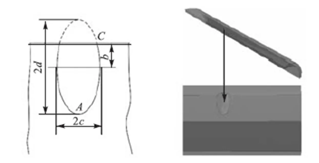
图1 双参数蚀坑模型
1.2 蚀坑-裂纹模型
目前学者认为,导致蚀坑向裂纹转变的条件之一为应力强度因子大于裂纹扩展的阈值[5].应力集中导致的蚀坑-裂纹在蚀坑的底部或肩部萌生;换句话说,裂纹首先在蚀坑肩部或底部转变成蚀坑-裂纹,之后再进一步扩展成全局性的裂纹,如图3所示.基于应力集中是导致裂纹萌生主导因素[16]的前提,由图2可知,在位置参数<0.2的条件下,裂纹在蚀坑处的萌生位置将始终位于蚀坑底部.本文旨在探究位置参数=0的情形下蚀坑参数、蚀坑深度对I型蚀坑-裂纹应力强度因子值的影响规律.
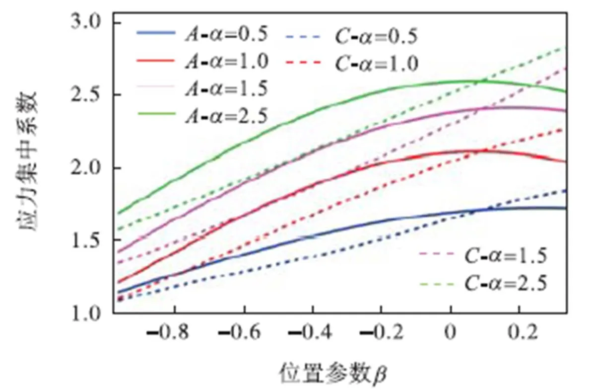
图2 不同蚀坑参数下蚀坑肩部和底部的应力集中系数
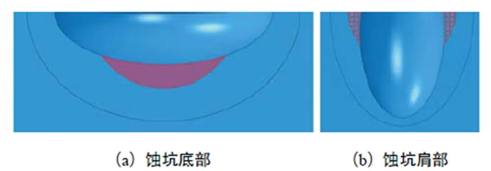
图3 萌生于蚀坑不同位置的蚀坑-裂纹示意
为了探究在管道内压作用下蚀坑参数和蚀坑深度对I型蚀坑-裂纹的影响,分别建立如图4所示的蚀坑-裂纹模型.

图4 蚀坑-裂纹模型
在研究蚀坑参数、蚀坑深度对I型蚀坑-裂纹应力强度因子值的影响时,首先要排除管厚对裂纹应力强度因子取值的影响.对于二维I型裂纹受管道内压作用下的应力强度因子表达式[17]为

(1)
式中:为管道内压;0为管道外径;为管厚;为裂纹长度;为形状因子,为(,)的函数,当/→0时,取固定值1.12.

表1 含I型蚀坑-裂纹的三维管道几何参数

Tab.1 Geometric parameters of the 3D pipeline with the I-shaped pit-crack
表2 内压作用下的管道外表面I型裂纹应力强度因子值

Tab.2 Stress intensity factor of I-shaped crack on the outer surface of the pipeline under internal pres-sure
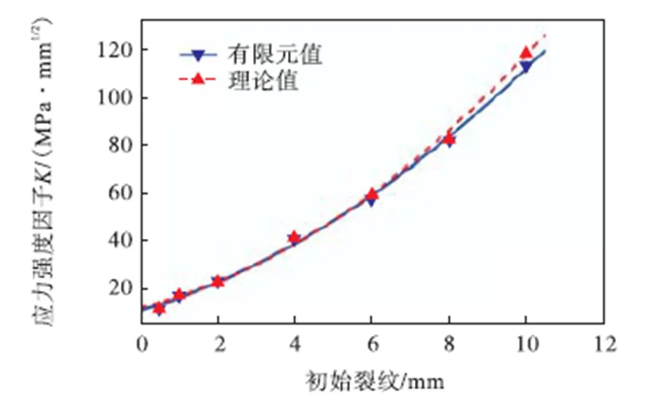
图5 有限元仿真和理论计算的示意

表3 蚀坑对I型裂纹应力强度因子的影响

Tab.3 Influence of the pit on the stress intensity factor of I-shaped crack
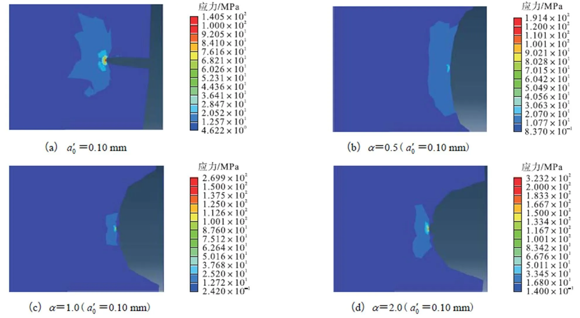
图6 二维模型的应力云图
蚀坑的存在明显改变了裂纹应力强度因子的取值,如图7所示.蚀坑+裂纹应力强度因子取值的变化趋势与纯裂纹的变化趋势明显不同;纯裂纹下,裂纹应力强度因子的取值与裂纹长度存在线性的变化关系;在蚀坑的影响下,应力强度因子的值随初始裂纹长度的变化趋势为先快速增大,后趋于定值.蚀坑深径比影响蚀坑+裂纹应力强度因子的取值;不同的蚀坑参数下,变化趋势趋于一致;同一初始裂纹长度下,随着变大,即蚀坑越窄深,蚀 坑+裂纹应力强度因子的取值越大.


图7 蚀坑对不同初始裂纹应力强度因子的影响
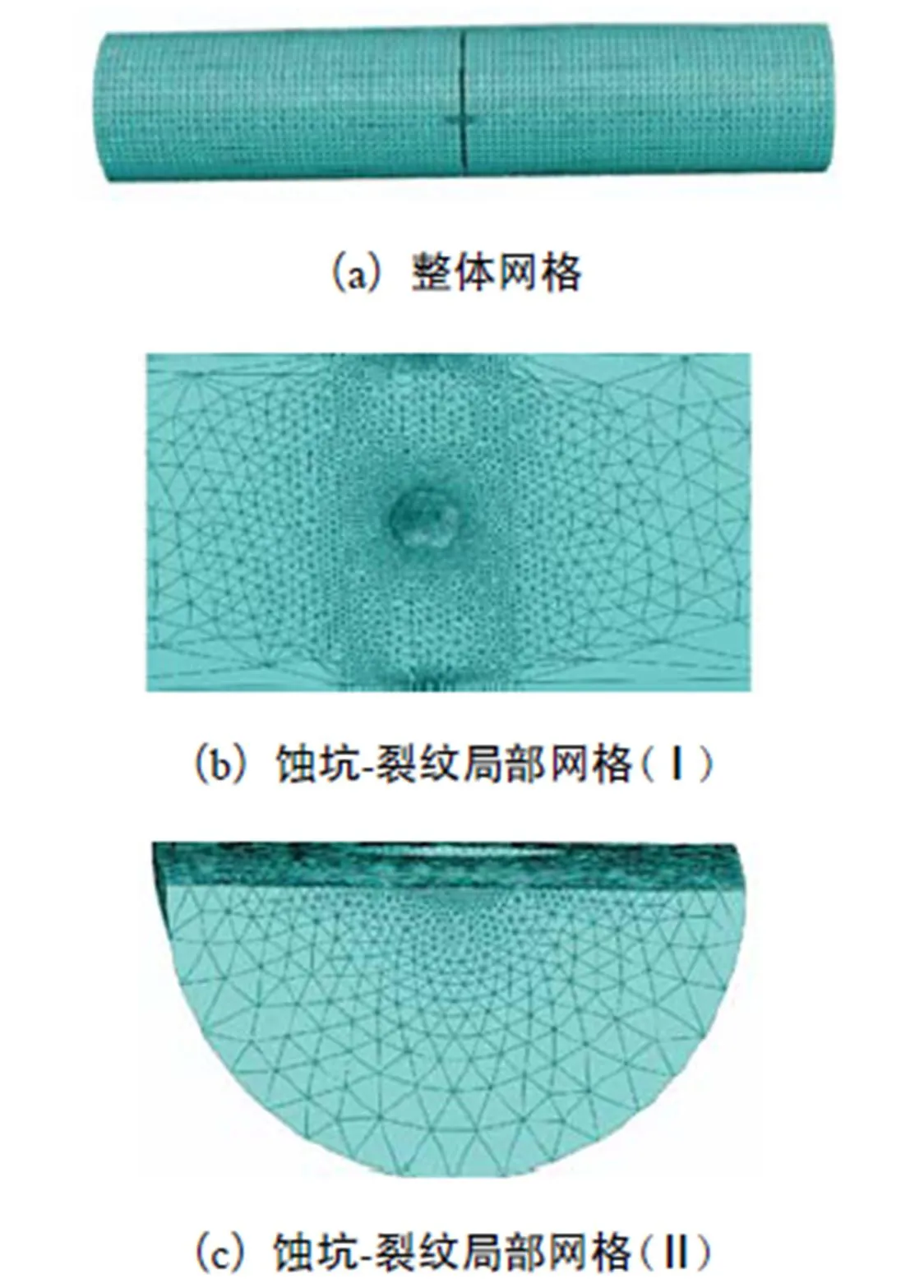
图8 I型蚀坑-裂纹三维模型的网格划分示意
2 蚀坑-裂纹应力强度因子分析

表4 不同蚀坑参数下的I型蚀坑-裂纹应力强度因子值
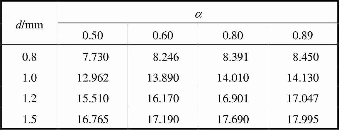
Tab.4 Stress intensity factor of I-shaped pit-crack under different parameters

图9 三维模型的应力云图
2.1 深径比a
深径比是表征点蚀坑形貌的一个重要参数.由图10可知,对于一定深度的点蚀坑来说,随着深径比的增大,蚀坑-裂纹应力强度因子的取值不断增大;各深度值下,深径比对蚀坑-裂纹应力强度因子取值的影响趋势趋于一致.
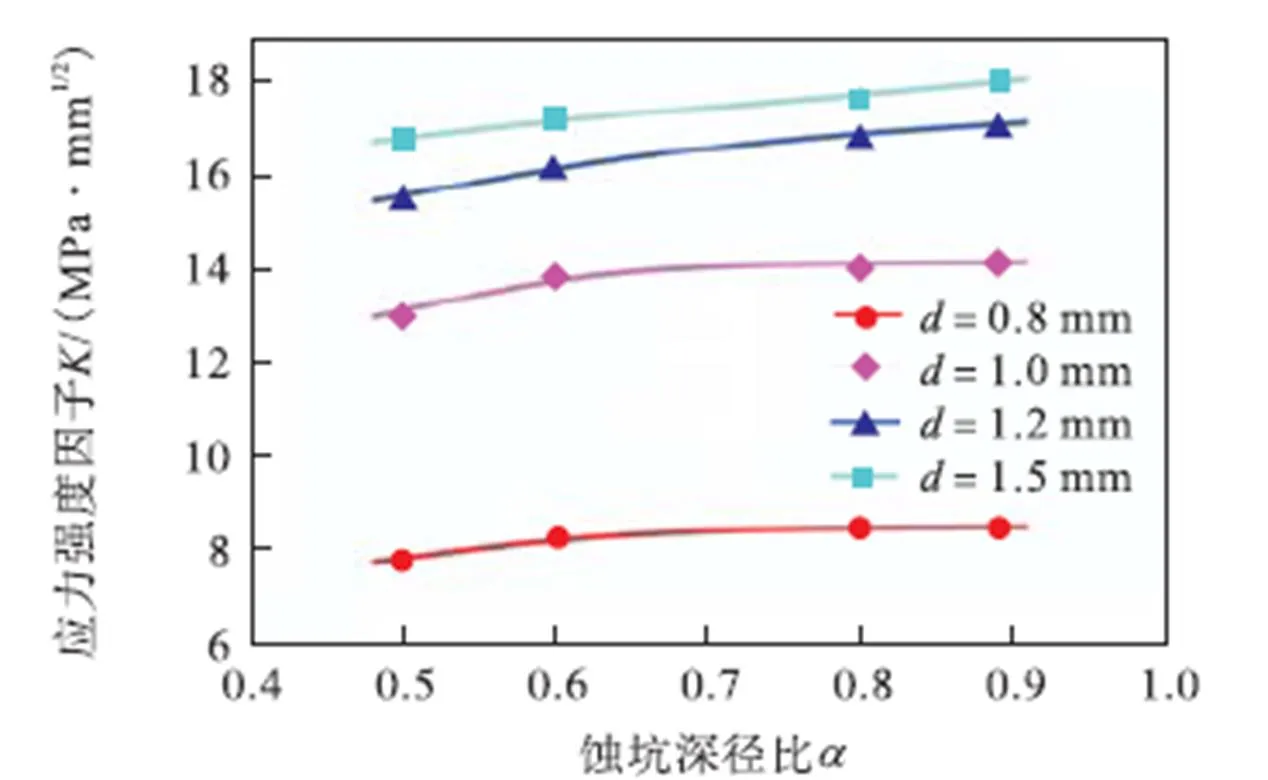
图10 深径比a 对蚀坑-裂纹应力强度因子的影响
2.2 蚀坑深度
蚀坑深度也是表征点蚀坑形貌的一个重要参数.由图11可知,对于一定的深径比而言,随着蚀坑深度的增大,蚀坑-裂纹应力强度因子值的变化趋势为先增大后趋于定值;各深径比下,蚀坑深度对蚀坑-裂纹应力强度因子取值的影响趋势趋于一致.
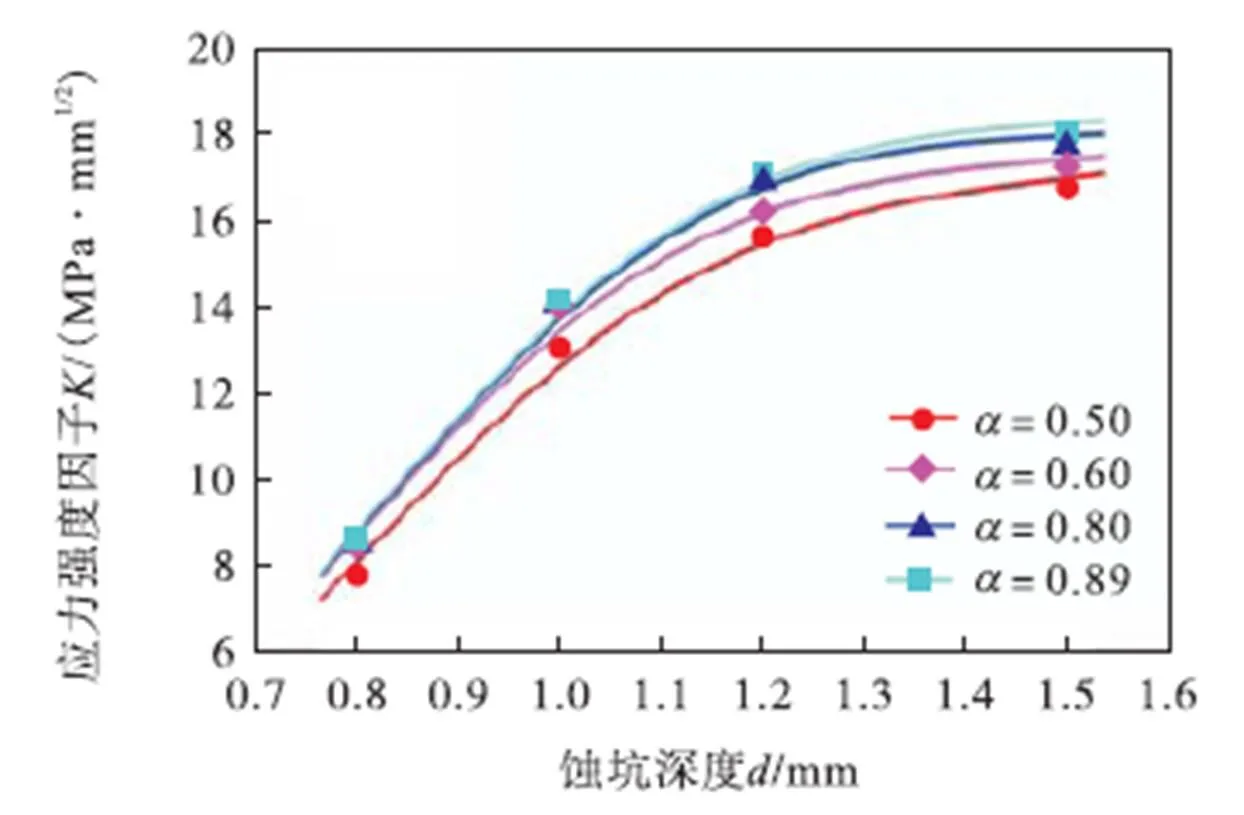
图11 深度d对蚀坑-裂纹应力强度因子的影响
2.3 蚀坑-裂纹形状因子F
对于裂纹应力强度因子的表达式,一般采用以下简化形式:

(2)

由图12可知,蚀坑深径比对取值的影响存在区间效应,换句话说,当深径比>0.60时,深径比对取值的影响有限.由图13可知,蚀坑深度对取值的影响同样存在区间效应,当蚀坑深度取值较小时,各深径比下的形状因子值趋于定值;随着蚀坑深度的增大,形状因子的取值不断变大,但变化速率为先快后慢.同时,随着蚀坑深度的增大,不同深径比下的取值各不相同.

图12 蚀坑-裂纹的形状因子F与蚀坑深径比a 的关系
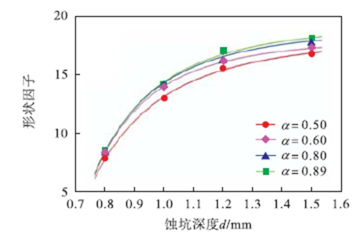
图13 蚀坑-裂纹的形状因子F与蚀坑深度d的关系
3 结 论
通过ABAQUS有限元中的扩展有限元方法,对处于内压作用下的管道外表面的I型蚀坑-裂纹开展了分析,可得到以下结论:
(1)蚀坑对裂纹应力强度因子的取值产生很大的影响,可明显的降低裂纹扩展的门槛值;
(2) 随着蚀坑参数深径比、深度的增大,蚀坑-裂纹应力强度因子的取值也逐渐变大;
(3)蚀坑参数深径比、深度对形状因子值的影响存在一定的区间效应.
[1] Muller M. Theoretical considerations on corrosion fatigue crack initiation[J]. Metallurgical Transactions A-Physical Metallurgy and Materials Science,1982(13):649-655.
[2] Chlistovsky R M,Heffernan P J,DuQuesnay D L. Corrosion-fatigue behavior of 7075-T651 aluminum alloy subjected to periodic overloads[J]. International Journal of Fatigue,2007(29):1941-1949.
[3] Li Shuxin,Akid R. Corrosion fatigue life prediction of a steel shaft material in seawater[J]. Engineering Failure Analysis,2013,34:324-334.
[4] Nan Z Y,Ishihara S,Goshima T. Corrosion fatigue behavior of extruded magnesium alloy AZ31 in sodium chloride solution[J]. International Journal of Fatigue,2008,30:1181-1188.
[5] Kondo Y. Prediction of fatigue crack initiation life based on pit growth[J]. Corrosion Science,1989,45(1):7-11.
[6] 蒋祖国. 飞机结构腐蚀疲劳[M]. 北京:航空工业出版社,1991.
Jiang Zuguo. Aircraft Structure Corrosion Fatigue[M]. Beijing:Aviation Industry Press,1991(in Chinese).
[7] Pidaparti R M,Patel R R. Correlation between corrosion pits and stresses in Al alloys[J]. Mater Lett,2008,21(3):57-62.
[8] 梁 瑞,张新燕,李淑欣,等. 半椭球蚀坑对圆棒应力集中的影响[J]. 中国腐蚀与防护学报,2013,6:532-536.
Liang Rui,Zhang Xinyan,Li Shuxin,et al. Influence of semi-ellipsoidal pit on stress concentration of round bar[J]. Journal of Chinese Society for Corrosion and Protection,2013,6:532-536(in Chinese).
[9] Cerit M,Genel K,Eksi S. Numerical investigation on stress concentration of corrosion pit[J]. Engineering Failure Analysis,2009,16:2467-2472.
[10] Zhang Y M,Fan M,Xiao Z M,et al.Fatigue analysis on offshore pipelines with embedded cracks[J]. Ocean Engineering,2016,117:45-56.
[11] 李 成,铁 瑛,郑艳萍. 不同的裂纹尺寸对椭圆形裂纹应力强度因子影响的研究[J]. 船舶力学,2011,15(10):1161-1165.
Li Cheng,Tie Ying,Zheng Yanping. Influence of different crack size on stress intensity factor of elliptical crack[J]. Journal of Ship Mechanics,2011,15(10):1161-1165(in Chinese).
[12] Newman J C,Raju I S. Stress-intensity factor for circumferencial surface crack in pipes and roads under tension and loads[J]. ASTM,STP905,1986:789-805.
[13] Rokhlin S I,Kim J Y,Nagy H,et al. Effect of pitting corrosion on fatigue crack initiation and fatigue life[J]. Engineering Fracture Mechanics,1999,62:425-444.
[14] 赵乾坤. 含内腐蚀缺陷-裂纹管道的应力强度因子与承压能力研究[D]. 重庆:西南石油大学,2017.
Zhao Qiankun. Study on stress intensity factor and bearing capacity of pipeline with internal corrosion defect-crack[D]. Chongqing:Southwest Petroleum Univer-sity,2017(in Chinese).
[15] 西田正孝. 应力集中[M]. 北京:机械工业出版社,1986.
Nishida Masako. Stress Concentration[M]. Beijing:Machinery Industry Press,1986(in Chinese).
[16] 周向阳,柯 伟. 点蚀坑的形貌与腐蚀疲劳裂纹萌生[J]. 金属学报,1992,28(8):356-360.
Zhou Xiangyang,Ke Wei. Pit morphology and corrosion fatigue crack initiation[J]. Chinese Journal of Metals,1992,28(8):356-360(in Chinese).
[17] 中国航空研究院. 应力强度因子手册[M]. 北京:科学出版社,1981.
China Aviation Research Institute. Stress Intensity Factor Handbook[M]. Beijing:Science Press,1981(in Chinese).
Analysis of the Stress Intensity Factor of a Pipeline Surface with a Pit-Crack
Yu Jianxing1, 2,Li Xiubo1, 2,Tan Yuna1, 2,Jin Chenghang1, 2,Feng Zhiqiang3,Han Xiangxi3,Fu Fei3
(1. State Kay Laboratory of Hydraulic Engineering Simulation and Safety,School of Civil Engineering,Tianjin University,Tianjin 300072,China;2. Collaborative Innovation Center for Advanced Ship and Deep-Sea Exploration,Shanghai 200240,China;3. Institute of Mechanical and Marine Engineering,Qinzhou University,Qinzhou 535011,China)
This study is aimed to address the problem of pits occurring on the surface of an in-service submarine pipeline subjected to corrosion fatigue and the subsequent damage caused. The stress intensity factor is one of the critical conditions for measuring the transition from pit to crack. The basis for corrosion fatigue life analysis with regard to the fracture mechanics is corrosion fatigue crack propagation. The unstable propagation of the crack is determined by the stress intensity factor. Therefore,it is imperative to combine the pit and crack stress intensity factors in terms of research on corrosion fatigue damage. On the basis of the idea that stress concentration is the main factor leading to the emanation of cracks,a two-parameter pit model,which can reasonably explain the phenomenon that cracks emanate from different locations depending where the pit is established. Under the action of fluid pressure in the pipeline,the axial I-shaped crack becomes the most dangerous crack type hoop stress. According to the concept of linear fracture mechanics,the stress intensity factor of the pit with the axial I-shaped crack on the surface of the pipeline under the hoop stress by 2D model was analyzed using the ABAQUS software. The results indicated that the pit has a significant effect on the value of the crack stress intensity factor,which can significantly reduce the threshold of crack propagation. Sensitivity analysis of the pit parameters affecting the stress intensity factor of the axial I-shaped pit-crack in the 3D model was conducted using the extended finite element method. The results indicated that the influence of the pit parameters on the pit-crack stress intensity factor and crack shape factor has different trends. With the increase in the depth-diameter ratioand depthof the pit parameters,the value of the pit-crack stress intensity factor also increased. A certain interval effect on the influence of the depth-diameter ratioand depthon the value of the shape factorwas observed.
two-parameter pit;crack;submarine pipeline;stress intensity factor
10.11784/tdxbz201809027
O346.2
A
0493-2137(2019)05-0522-07
2018-09-11;
2018-11-02.
余建星(1958— ),男,教授.
余建星,yjx2000@tju.edu.cn.
国家科技重大专项资助项目(2016ZX05028005-004);国家自然科学基金青年基金资助项目(51609169).
the National Science and Technology Major Project of the Ministry of Science and Technology of China(No. 2016ZX05028005-004),the Young Scientists Fund of National Natural Science Foundation of China(No. 51609169).
(责任编辑:王新英)

