
In-situ Synthesis of Perovskite SrTiO3 Nanostructures with Modified Morphology and Tunable Optical Absorption Property
2019-01-30 06:47LIUXiaoYuanLIUBaoDanJIANGYaNanWANGKeZHOUYangYANGBingZHANGXingLaiJIANGXin
无机材料学报 2019年1期
LIU Xiao-Yuan, LIU Bao-Dan, JIANG Ya-Nan, WANG Ke, ZHOU Yang, YANG Bing, ZHANG Xing-Lai, JIANG Xin
LIU Xiao-Yuan1,2, LIU Bao-Dan1, JIANG Ya-Nan1, WANG Ke1,2, ZHOU Yang1,2, YANG Bing1, ZHANG Xing-Lai1, JIANG Xin1
Synthesis of Perovskite SrTiO3Nanostructures with Modified Morphology and Tunable Optical Absorption Property
LIU Xiao-Yuan1,2, LIU Bao-Dan1, JIANG Ya-Nan1, WANG Ke1,2, ZHOU Yang1,2, YANG Bing1, ZHANG Xing-Lai1, JIANG Xin1
(1. Shenyang National Laboratory for Materials Science, Institute of Metal Research, Chinese Academy of Sciences, Shenyang 110016, China; 2. School of Materials Science and Engineering, University of Science and Technology of China, Hefei 230026, China)
As a perovskite family member, SrTiO3shows significant applications in the fields of solar cells, photocatalysis, fuel cells and superconducting as a dependence of its crystallinity, morphology, crystal facet and optical properties. In this work, we reported ansynthetic approach of SrTiO3nanostructures with modified morphology and tunable optical absorption properties based on conventional plasma electrolytic oxidation (PEO) associated with hydrothermal method. The morphology of SrTiO3nanostructures can be selectively modified from microcubes with smooth facets to ultrathin nanosheets by controlling the concentration of Sr source during PEO process. It is found that both SrTiO3microcubes and Sr1–δTiO3nanosheets are well-crystallized single crystals. UV-Vis diffuse reactance spectrum (DRS) measurement reveals that Sr1–δTiO3nanosheets with thin thickness show obvious blue-shift of absorption edge in comparison with SrTiO3microcubes due to the size effect. Finally, the morphology evolution and nucleation mechanism of SrTiO3nanostructuresgrown on PEO film is discussed.
SrTiO3;growth; plasma electrolytic oxidation; morphology tuning; optical property
Over the past few decades, perovskite materials owning a featured ABX3molecular formula and fascinating functional properties have received global research interest and have been widely investigated. Extensive efforts have been paid to improve the performances of these existed ABX3materials and to seek new members in perovskite family[1-5]. In this way, the development of an efficient and accessible approach is of great importance for the nucleation design and crystallization control, as well as the rational tailoring of morphology, geometrical shape, surface characteristics and size, which have close relationship to the physicochemical properties and functional performances of these perovskite materials[6-7].
As one of the most popular and versatile materials in perovskite family[8], SrTiO3shows significant applications in diverse fields including solar cells[9-10], photocatalysis[11-14], water splitting[14-16], fuel cells[17], superconducting[18],. Recently, with the development of nanoscience and nanotechnology, nanostructured SrTiO3has also received tremendous attention due to its peculiar properties and versatile functions in above-mentioned fields. So far, various SrTiO3nanostructures including nanowires[12], nanocubes[19-21]and truncated octahedrons[22]have been successfully obtained through different synthetic methods. However, the polycrystalline SrTiO3gives rise to the existence of massive grain boundaries, generating a natural energy barrier for the electron transport, and thus deteriorates the electric property of SrTiO3. Therefore, SrTiO3nanostructures with excellent crystal quality are definitely required. On the other hand, most of the reported SrTiO3nanostructures are still in powder form, which will undoubtedly bring mass loss during cyclic utilization. Therefore, the fixing of SrTiO3nanostructure with strong substrate adherence is preferable.
From the point of crystallography, SrTiO3shows a simple cubic (s.c.) crystallographic structure and a space group Pm-3m, implying a minimum surface energy in (001) plane. For this reason, the crystallographic morphology of SrTiO3is favorable to form cube-like structure. However, the functional properties of SrTiO3nanostructures such as catalytic reactions are strongly dependent on its crystal facet. Considering all these points, an approach that can realize thegrowth of SrTiO3nanostructures for strong substrate adherence, the crystal facet tailoring for selective catalytic reaction and superior crystalquality is generally needed for further promoting their applications in diverse fields.
As a conventional surface treatment method for enhancing metal wear resistance, plasma electrolytic oxidation (PEO) technology owns many unique advantages. It has been regarded as an ideal method to prepare metallurgical bonded film with strong adherence for cyclic utilization in some harsh environment. Furthermore, the porous PEO film can provide sufficient nucleation sites for the furthergrowth of SrTiO3nanostructures. In this paper, a two-step method by combining traditional PEO and hydrothermal method tosynthesize SrTiO3nanostructures on metal substrate was developed based on our previous work[23-25]. The PEO process is utilized to produce Sr/Ti contained porous film, while the hydrothermal process enables a rational tailoring of the morphology of SrTiO3from microcube to nanosheet. Through detailed structural characterizations, we confirmed that both the SrTiO3microcube and Sr1–δTiO3nanosheet are single crystals, and the two nanostructures show (100) and (110) exposed facets, respectively. It is expected that this hybrid synthetic strategy will open up more opportunities for SrTiO3nanostructures to be used in diverse fields and can thus be further extended to the synthesis of a variety of metal oxide nanostructures with predominant advantages and promising applications.
1 Experimental
1.1 PEO film fabrication
The PEO treatment was applied to preparation of porous TiO2film in accordance with the experiment routes of our previous work[23-26]. In a typical process, Ti substrate was used as anode, two pieces of high-purity graphite served as the counter electrode and the mixture of Na2B4O7, Sr(AC)2, NaOH and EDTA-2Na was used as electrolyte. During a normal PEO process, the Ti substrate was immersed into the electrolyte under pulse DC power supply and charged for 12 min. The temperature of the electrolyte was kept at around 20℃. The current density, duty cycle and frequency were maintained at 0.13 A/cm2, 60% and 1000 Hz, respectively.
1.2 In-situ synthesis of SrTiO3 nanostructures
In this step, porous PEO film containing Sr source was used as the nucleation site of SrTiO3nanostructures. The film was vertically immersed into 15 mL NaOH solution (0.5 mol/L, 1 mol/L, 1.5 mol/L) in a Teflon-lined autoclave and heated at 180℃ for different hydrothermal durations (1 h, 2 h, 4 h, 6 h, 8 h).
1.3 Characterizations of SrTiO3 nanostructures
The phases and crystal structures of SrTiO3samples were characterized by X-ray diffraction (XRD, Rigaku D/max 2400). 3D spatial profiles of PEO film was measureda 3D X-ray microscope (Xradia Versa XRM 500). X-ray photoelectron spectroscopy (XPS, Thermal VG/ESCALAB250) was used to obtain the binding energy of SrTiO3samples. The morphology and composition of SrTiO3nanostructures were characterized by a field-emission scanning electron microscopy (FE-SEM, FEI Inspect F50) equipped with a Quanta 600 Energy Dispersed X-ray spectrometer (EDS) system. The microstructure and crystallinity of SrTiO3nanostructures were analyzed using a 200 kV transmission electron microscopy (TEM, Tecnai G2 F20). UV-Vis diffuse reflectance spectra (DRS) of SrTiO3nanostructures were obtained on a HITACHI U-3900 spectrophotometer.
2 Results and discussions
Previous work has demonstrated the merits of PEO method in obtaining metal oxide nanostructures with strong substrate adherence[23-27]. The porous film provides the nucleation sites and the precursor source for the formation of metal oxide nanostructures. In this work, the PEO film exhibits a typical porous structure comprising of numerous volcano-like channels formed during the instantaneous micro-arc discharge (Fig. S1). The porous structure is very uniform with the pore size varying from hundreds of nanometers to several micrometers. The depth of the pores can be up to 6 μm, which can be confirmed from the 3D X-Ray image (Fig. S2). In addition, the pores distribute homogeneously both outside and inside of the TiO2film, providing sufficient nucleation sites for thegrowth of SrTiO3nanostructures.
XRD measurement was carried out to investigate the structure/phase information of all PEO samples before (Fig. S3) and after (Fig. 1) hydrothermal treatment. The (110) (101) and (111) peaks of TiO2in rutile phase (JCPDS no. 21-1276;==0.495 nm,=0.296 nm) at 2=27.4°, 36.1°and 41.2°can be clearly distinguished. In addition, a slight trace of (101) peak at 2=25.3°canalso be detected, which originates from anatase phase TiO2(JCPDS no. 21-1272;==0.379 nm,=0.951 nm). The coexistence of these two TiO2phases in the PEO film coincides with the results of other groups[28]. The diffraction peaks at 22.4°, 40.0°and 46.5°for PEO films (Fig. S3) obtained under low concentration of Sr(AC)2(LSCE) match well with the (110) (111) and (200) lattice planes of SrTiO3(JCPDS no. 35-0734;===0.391 nm), which means that SrTiO3has already been formed during the PEO process. However, these peaks of SrTiO3in PEO film disappear under high concentration of Sr(AC)2(HSCE). This can be understood that the excessive Sr2+could lead to the sedimentation of phosphate radical and cause the weakening of micro-arc discharge. As a result, the crystallization of Sr species in PEO film is inhibited due to the lack of discharge energy. The Ti, Sr and O concentrations in PEO film are ascertained through EDS measurement (Table S1). That all samples contain a certain amount of Sr element although the SrTiO3phase is not detected in the case of HSCE. A reasonable reason is that SrTiO3exists in amorphous phase in PEO matrix. This assertion could be further verified from the diffraction dome in XRD pattern in the range of 23°-36°, which is in good agreement with the formation of amorphous tungstate fabricated by PEO method[23-24].

Fig. 1 XRD patterns of SrTiO3 samples prepared under different hydrothermal conditions
Hydrothermal treatment is applied on PEO film for thegrowth of SrTiO3nanocrystal. Fig. 2 shows the typical morphology of SrTiO3nanocrystalsnucleated on HSCE PEO film after hydrothermal treatment. It can be seen that the surface of the PEO film is fully covered with numerous cube-like nucleus with regular crystalline facets. Each micro-cube shows smooth surface and sharp edges, and the typical size of these microcubes is 1 µm -3 µm. In addition, it is also found that NaOH solution plays a key role in the formation of SrTiO3nanostructures. The addition of NaOH in hydrothermal reaction will promote the high density of nucleation and accelerate the growth rate of SrTiO3nanocrystals (Fig. S4)[12], while few SrTiO3nanocrystals can be found without the participation of NaOH solution (Fig. S5). As we prolong the treating time, no evident difference in size and morphology of SrTiO3microcubes is observed (Fig. S4(a)-(d)), indicating that the PEO film has approximately reached the precipitation-dissolution equilibrium under 0.5 mol/L NaOH solution in only 1 h. The hydrothermal growth of SrTiO3nanocrystals under other NaOH concentrations (1.0 mol/L, 1.5 mol/L) was also implemented (Fig. S6-S7). Interestingly, the morphology of these samples is quite similar only except for some traces of etching at the edges and corners of microcubes (Figure S6(a)-(c)), which is caused by the dissolution of low coordinated Sr and Ti atoms. Compositional analysis on the microcube layer using EDS measurement shows that the atomic percentages of Sr, Ti and O elements are 20.77%, 24.16% and 55.06% (Table S2), matching well with the stoichiometric ratio of standard SrTiO3. The cubic SrTiO3phase can also be confirmed by TEM analysis. Fig. 2(c) shows the low-magnification TEM image of SrTiO3microcubes assembled together with all exposed crystal facets of (100) planes and 90°included angle of two random adjacent planes. The HRTEM image and FFT pattern along the [110] zone axis (Fig. 2(d-e)) further indicates that the microcube is single crystal without obvious structure defect. The inter-planar spacing between neighbour lattices is 0.393 nm and 0.281 nm, respectively, which matches well with the distances of (100) and (011) planes of cubic SrTiO3. All these compositional and structural results, together with XRD results (Fig. 1), have firmly demonstrated the formation of high-quality cubic SrTiO3on the surface of porous TiO2film and similar morphology has been observed in previous work[12].
When the Sr content in initial electrolyte was reduced, the SrTiO3nanocrystals show quite different morphology as compared to SrTiO3microcubes. In SEM images (Fig. 3(a)) widespread ultra-thin nanosheets take the place of SrTiO3microcubes and fully cover the PEO film. Fig. S8 gives the SEM image of PEO sample treated in 1 mol/L NaOH for different durations. It can be seen that the size of nanosheets varies among 100 nm-200 nm as the reaction time is 0.5 h (Fig. S8(a)), and then grows to micron scale as the time extends to 1 h (Fig. S8(b)) and 2 h (Fig. S8(c)). Further increasing the treating time causes the edge curling and assembling of sheet structure (Fig. S8(d)-(e)), which is probably induced by the stress release. Adjusting the NaOH concentration also leads to the size evolution and morphology changing of nanosheets. Taking Fig. S8, Fig. S9 and Fig. S10 as comparisons, the sheet size shows an increasing tendency in pace with the increase of NaOH concentration. Through the HRTEM image (Fig. 3(d)) and corresponding FFT pattern (Fig. 3(e)), we can calculate the interlayer spacing of such nanosheet to be 0.371 nm along (001) plane and 0.278 nm along (110) plane of SrTiO3.

Fig. 2 (a,c) SEM image and TEM bright field image of SrTiO3 microcubes; (b) Crystallographic model of cube-like SrTiO3 nanostructure; (d,e) HRTEM image and FFT pattern of SrTiO3 microcubes

Fig. 3 (a,c) SEM image and TEM bright field image of Sr1–δTiO3 nanosheets; (b) Crystallographic model of sheet-like Sr1–δTiO3; (d,e) HRTEM image and FFT pattern of Sr1–δTiO3 nanosheets
The exposed facet is calculated to be (11¯0) crystalline plane. Additionally, it can be seen that the crystalline quality of nanosheet is not so good as microcube (Fig. 2(d)). EDS data (Table S2) shows that the Sr/Ti ratio of SrTiO3nanosheets is about 0.21, which is much smaller than the stoichiometric ratio of standard SrTiO3. In order to get more convincing conclusion, XPS element component analysis is used to collect the signals of the topmost surface of SrTiO3nanosheets. The Sr/Ti ratio of nanosheet is found to be around 0.31 (Table S3), which is similar to the EDS result. Thus these nanosheets can be regarded more accurately as Sr1–δTiO3. The XPS result (Fig. 4) of Sr exhibits two peaks at around 133.7 eV and 135.4 eV which correspond to the 3d5/2and 3d3/2electron orbit of Sr2+. Two peaks of Ti2p located at 458.0 eV (2p3/2) and 463.8 eV (2p1/2) are observed, which belong to Ti4+in SrTiO3[12, 29], while no signal of Ti4+from TiO2is detected due to the full covering of Sr1-δTiO3nanosheets.
Based on all the results above, the tentative formation mechanism of SrTiO3microcubes and nanosheets is proposed (Fig. 5). The PEO film serves as both substrate and precursor for the nucleation of SrTiO3nanocrystals and the Sr/Ti source for hydrothermal reaction. During hydrothermal process, Sr/Ti species in the PEO film can quickly dissolve under elevated temperature in alkaline environment, then the released Sr2+and Ti4+species suffer from a hydrolysis process. The hydrolysis of Ti4+is very quick[30], leading to the rapid formation of [Ti(OH)]4-y, which is further aggregated into colloid species {[Ti(OH)]4-}. [Sr(OH)]2-xare also formed at the same time. In alkaline condition, [Sr(OH)]2-xwill break the Ti-O bond to incorporate into the Ti-O cluster to form SrTiO3[31-33]. Since PEO film under LSCE could only provide a relatively low Sr concentration (Table S1) during SrTiO3formation process, the [Sr(OH)]2-xcouldn’t penetrate into the whole Ti-O sol. As a result, Ti-O prefers to exhibit a sheet-like morphology with insufficient incorporation of Sr and thus leads to the formation of non-stoichiometric Sr1–δTiO3nanosheets. The condition is contrary in HSCE sample with a Sr/Ti ratio of 0.79. The increase of Sr concentration around HSCE sample can also lead to faster growth rate of SrTiO3cube than that of Sr1–δTiO3nanosheet, which is evidenced in SEM results (Fig. S4-S10).

Fig. 4 XPS spectra of (a) Sr3d, (b) Ti2p and (c) O1s of Sr1–δTiO3 nanosheets prepared under 1.0 mol/L NaOH solution for 8 h
The optical properties of SrTiO3microcube and Sr1-δTiO3nanosheets were roughly examined through a UV-Vis spectrometer. Fig. 6 shows the UV-Vis absorption spectra of PEO film and SrTiO3samples synthesized under different conditions. It can be seen that the SrTiO3microcube has only strong absorption around 390 nm with smaller inclination, while the Sr1-δTiO3nanosheets show two absorption edges at around 335 nm and 400 nm, respectively. Apparently, the 390 nm absorption is directly from SrTiO3microcube, which corresponds to a band gap of 3.18 eV. For Sr1-δTiO3nanosheets, the absorption edge located at around 335 nm, which corresponds to a band gap of 3.71 eV, exhibits obvious blue-shift in comparison with the bulk SrTiO3(3.25 eV) due to size effect[34-35], while the 400 nm absorption edge can be attributed to the electron transition of rutile TiO2. In addition, the absorption intensity at 335 nm exhibts an increasing tendency along with the increase of NaOH concentration and soaking time, indicating more Sr1-δTiO3nanosheets formed on the surface of PEO film. What’s more, from the SEM images (Fig. S8-S10) of nanosheet samples, it can also be seen that the amount of nanosheets shows an increasing tendency along with the increase of NaOH concentration and soaking time. As a result, it can be concluded that the SEM results (Fig. S8-S10) and the UV-Vis absorption spectra of nanosheet sample strongly support the assertion that the nanosheets are mainly composed of Sr1–δTiO3. The difference of absorption features between SrTiO3cubes and Sr1–δTiO3nanosheets will provide more opportunities for promising applications in the fields of photocatalytic water-splitting, photocatalytic degradation and heterogeneous catalysis,.

Fig. 5 Schematic diagram describing the formation process of SrTiO3 microcubes and Sr1–δTiO3 nanosheets

Fig. 6 UV-Vis spectra of PEO film, SrTiO3 microcubes and Sr1-δTiO3 nanosheets under different hydrothermal conditions
3 Conclusions
SrTiO3microcubes and Sr1–δTiO3nanosheets have beenfabricated on PEO film through a combined technology. The SrTiO3microcubes obtained under HSCE show a regular cubic structure with (001) exposed crystal facets and superior crystalline quality without defects. Reducing the concentration of Sr source induces an obvious morphology evolution from microcubes to Sr1–δTiO3nanosheets with a thickness of about several nanometers and (110) exposed facet. In addition, the two types of SrTiO3nanostructures show significant difference in composition and optical absorption properties. SrTiO3microcubes own a higher Sr concentration and a bulk-like optical absorption behavior, while Sr1–δTiO3nanosheets with insufficient Sr content exhibit obvious blue-shift in optical absorption due to the size effect. It is believed that the initial Sr/Ti atomic ratio in PEO film is mainly responsible for the morphology evolution of SrTiO3nanostructures. This feasiblesynthetic strategy to SrTiO3nanostructures with modified morphology, tunable band gap and optical properties will pave a solid way toward their promising application in the fields of photocatalysis for clean energy and environmental processing.
[1] KAZIM S, NAZEERUDDIN M K, GRATZEL M,. Perovskite as light harvester: a game changer in photovoltaics..., 2014, 53(11): 2812–2824.
[2] SULAEMAN U, YIN S, SATO T. Solvothermal synthesis and photocatalytic properties of chromium-doped SrTiO3nanoparticles.., 2011, 105(1/2): 206–210.
[3] IWASHINA K, KUDO A. Rh-doped SrTiO3photocatalyst electrode showing cathodic photocurrent for water splitting under visible- light irradiation.., 2011, 133(34): 13272–13275.
[4] COMES R B, SMOLIN S Y, KASPAR T C,. Visible light carrier generation in co-doped epitaxial titanate films.., 2015, 106(9): 092901–1–5.
[5] PARK K I, XU S, LIU Y,. Piezoelectric BaTiO3thin film nanogenerator on plastic substrates., 2010, 10(12): 4939–4943.
[6] GRABOWSKA E. Selected perovskite oxides: characterization, preparation and photocatalytic properties—a review., 2016, 186: 97–126.
[7] MADHAVAN B, ASHOK A. Review on nanoperovskites: materials, synthesis, and applications for proton and oxide ion conductivity., 2014, 21(3): 1–10.
[8] KUDO A, MISEKI Y. Heterogeneous photocatalyst materials for water splitting., 2009, 38(1): 253–278.
[9] DIAMANT Y, CHEN S G, MELAMED O,. Core-shell nanoporous electrode for dye sensitized solar cells: the effect of the SrTiO3shell on the electronic properties of the TiO2core., 2003, 107(9): 1977–1981.
[10] LENZMANN F, KRUEGER J, BURNSIDE S,. Surface photovoltage spectroscopy of dye-sensitized solar cells with TiO2, Nb2O5, and SrTiO3nanocrystalline photoanodes: indication for electron injection from higher excited dye states., 2001, 105(27): 6347–6352.
[11] KANG Q, WANG T, LI P,. Photocatalytic reduction of carbon dioxide by hydrous hydrazine over Au-Cu alloy nanoparticles supported on SrTiO/TiO coaxial nanotube arrays., 2014, 54(3): 841–845.
[12] CAO T, LI Y, WANG C,. A facilehydrothermal method to SrTiO3/TiO2nanofiber heterostructures with high photocatalytic activity., 2011, 27(6): 2946–2952.
[13] LONG Z, WEI X H, QIU X Q. Preparation of SrTiO3cubes by molten salt method and its surface ions modification with Cu(II) clusters.., 2013, 28(10): 1103–1107.
[14] ZHU Y R, TANG Y G, YAN J H,. Preparation and photocatalytic hydrogen generation activity of nitrogen doped SrTiO3under visible light irradiation.., 2008, 23(3): 443–448.
[15] JI L, MCDANIEL M D, WANG S,. A silicon-based photocathode for water reduction with an epitaxial SrTiO3protection layer and a nanostructured catalyst., 2014, 10(1): 84–90.
[16] YAN J H, ZHANG L, ZHU Y R,. Preparation and photocatalytic hydrogen production of NiO(CoO)/N-SrTiO3heterojunction complex catalyst under simulated sunlight irradiation.., 2009, 24(4): 666–670.
[17] KOVALEVSKY A V, POPULOH S, PATRÍCIO S G,. Design of SrTiO3-based thermoelectrics by tungsten substitution., 2015, 119(9): 4466–4478.
[18] OHTOMO A, HWANG H Y. A high-mobility electron gas at the LaAlO3/SrTiO3heterointerface., 2004, 427(6973): 423– 426.
[19] KUANG Q, YANG S. Template synthesis of single-crystal-like porous SrTiO3nanocube assemblies and their enhanced photocatalytic hydrogen evolution., 2013, 5(9): 3683–3690.
[20] ZHAN H, CHEN Z G, ZHUANG J,. Correlation between multiple growth stages and photocatalysis of SrTiO3nanocrystals., 2015, 119(7): 3530–3537.
[21] SREEDHAR G, SIVANANTHAM A, BASKARAN T,. A role of lithiated sarcosine TFSI on the formation of single crystalline SrTiO3nanocubeshydrothermal method., 2014, 133: 127–131.
[22] DONG L, LUO Q, CHENG K,. Facet-specific assembly of proteins on SrTiO3polyhedral nanocrystals.., 2014, 4: 5084–1–5.
[23] JIANG Y, LIU B, ZHAI Z,. A general strategy toward the rational synthesis of metal tungstate nanostructures using plasma electrolytic oxidation method.., 2015, 356: 273–281.
[24] JIANG Y N, LIU B D, YANG W J,. New strategy for thesynthesis of single-crystalline MnWO4/TiO2photocatalysts for efficient and cyclic photodegradation of organic pollutants.., 2016, 18(10): 1832–1841.
[25] JIANG Y, LIU B, YANG L,. Size-controllable Ni5TiO7nanowires as promising catalysts for CO oxidation.., 2015, 5: 14330–1–10.
[26] JIANG Y, LIU B, YANG W,. Crystalline (Ni1–xCo)5TiO7nanostructures grownon a flexible metal substrate used towards efficient CO oxidation., 2017, 9(32): 11713–11719.
[27] JIANG X, ZHANG L, WYBORNOV S,. Highly efficient nanoarchitectured Ni5TiO7catalyst for biomass gasification., 2012, 4(8): 4062–4066.
[28] BARATI N, YEROKHIN A, GOLESTANIFARD F,. Alumina- zirconia coatings produced by plasma electrolytic oxidation on Al alloy for corrosion resistance improvement.., 2017, 724: 435–442.
[29] HAASCH R T, BRECKENFELD E, MARTIN L W. Single crystal perovskites analyzed using X-ray photoelectron spectroscopy: 1. SrTiO3(001)., 2014, 21(1): 87–94.
[30] MOCKEL H, GIERSIG M, WILLIG F. Formation of uniform size anatase nanocrystals from bis(ammoniumlactato)titanium dihydroxide by thermohydrolysis., 1999, 9(12): 3051–3056.
[31] KATO K, DANG F, MIMURA K I,. Nano-sized cube-shaped single crystalline oxides and their potentials, composition, assembly and functions., 2014, 25(5): 1401–1414.
[32] FUJINAMI K, KATAGIRI K, KAMIYA J,. Sub-10 nm strontium titanate nanocubes highly dispersed in non-polar organic solvents., 2010, 2(10): 2080–2083.
[33] GUO Y, LIU G, REN Z,. Single crystalline brookite titanium dioxide nanorod arrays rooted on ceramic monoliths: a hybrid nanocatalyst support with ultra-high surface area and thermal stability.., 2013, 15(41): 8345–8352.
[34] AKKERMAN Q A, MOTTI S G, KANDADA A R S,. Solution synthesis approach to colloidal cesium lead halide perovskite nanoplatelets with monolayer-level thickness control.., 2016, 138(3): 1010–1016.
[35] XU Z T, MITZI D B, DIMITRAKOPOULOS C D,. Semiconducting perovskites (2-XC6H4C2H4NH3)2SnI4(X = F, Cl, Br): steric interaction between the organic and inorganic layers., 2003, 42(6): 2031–2039.
Supporting information
Synthesis of Perovskite SrTiO3Nanostructures with Modified Morphology and Tunable Optical Absorption Property
LIU Xiao-Yuan1,2, LIU Bao-Dan1, JIANG Ya-Nan1, WANG Ke1,2, ZHOU Yang1,2, YANG Bing1, ZHANG Xing-Lai1, JIANG Xin1
(1. Shenyang National Laboratory for Materials Science, Institute of Metal Research, Chinese Academy of Sciences, Shenyang 110016, China; 2. School of Materials Science and Engineering, University of Science and Technology of China, Hefei 230026, China)

Fig. S1 SEM images of PEO film
Fig. S2 (a, c) X-ray diffraction topography (XRT) images of PEO film surface morphology and (b, d) cross section images
Table S1 EDS results of PEO film prepared in high Sr concentration electrolyte (HSCE) and low Sr concentration electrolyte (LSCE)

SampleO/at%Ti/at%Sr/at%n(Sr) : n(Ti) HSCE79.3511.519.140.79 LSCE53.9337.328.750.23
Table S2 EDS results of SrTiO3microcubes and Sr1–TiO3nanosheets

SampleO/at%Ti/at%Sr/at%n(Sr) : n(Ti) Microcube55.0624.1620.770.86 Nanosheet61.6531.656.70.21
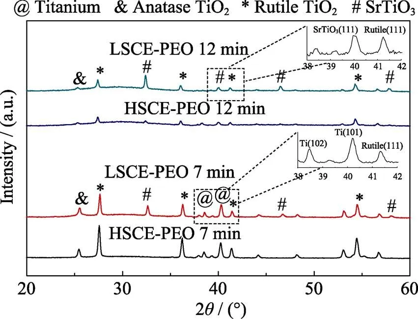
Fig. S3 XRD patterns of PEO films prepared under different conditions
LSCE, 7 min PEO treating time; LSCE, 12 min PEO treating time, HSCE, 7 min PEO treating time and HSCE, 12 min PEO treating time
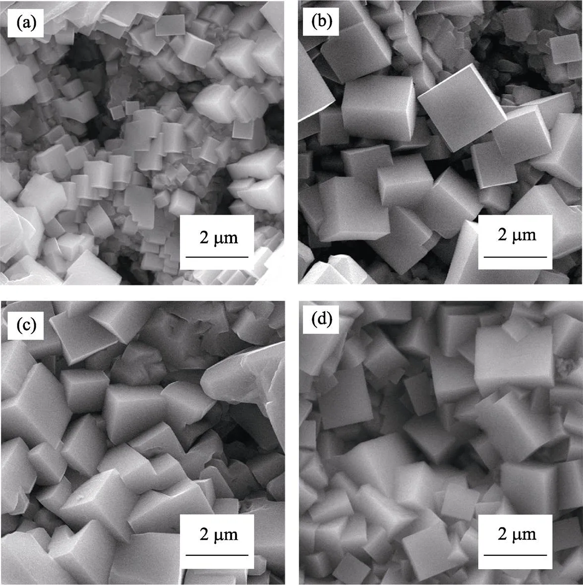
Fig. S4 SEM images of SrTiO3microcubes obtained on PEO film under HSCE and in 0.5 mol/L NaOH with different durations
(a) 180℃, 1 h; (b) 180℃, 4 h; (c) 180℃, 6 h; (d) 180℃, 8 h
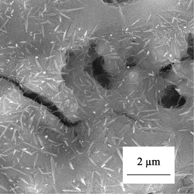
Fig. S5 Surface morphology of PEO film after hydrothermal treating (without NaOH, 180℃, 8 h)
Table S3 XPS element analysis of Sr1–δTiO3nanosheets

SampleO/at%B/at%Ti/at%Sr/at%n(Sr) : n(Ti) Nanosheet69.950.7022.396.960.31
Fig. S6 SEM images of SrTiO3microcubes obtained on PEO film under HSCE and in 1.0 mol/L NaOH with different durations
(a) 180℃, 0.5 h; (b) 180℃, 1 h; (c) 180℃, 2 h; (d) 180℃, 8 h

Fig. S7 SEM images of SrTiO3microcubes obtained on PEO film under HSCE and in 1.5 mol/L NaOH with different durations
(a) 180℃, 4 h; (b) 180℃, 6 h; (c) 180℃, 8 h
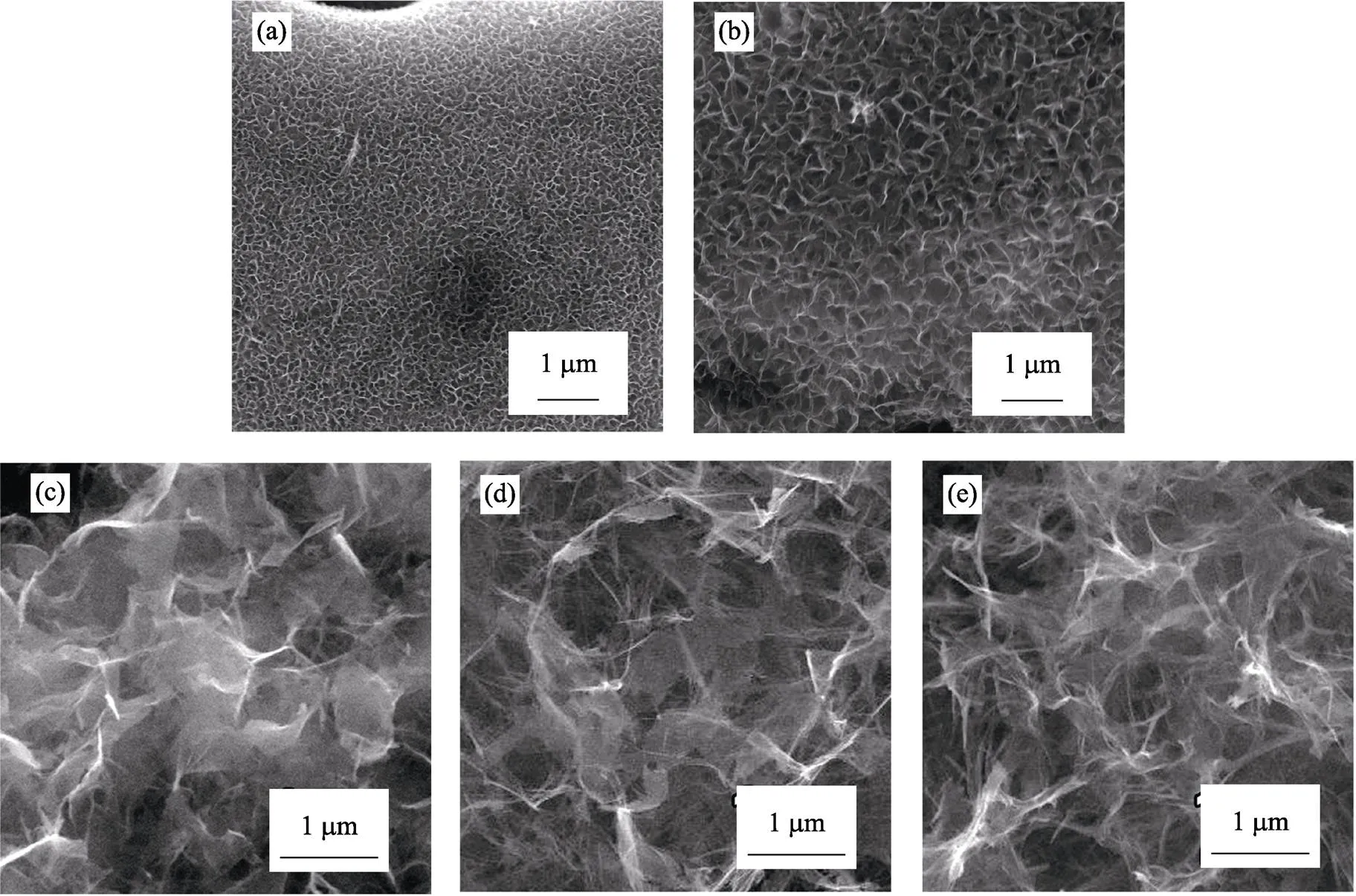
Fig. S8 SEM images of Sr1–TiO3nanosheets obtained on PEO film under LSCE and in 1.0 mol/L NaOH with different durations
(a) 180℃, 0.5 h; (b) 180℃, 1 h; (c) 180℃, 2 h; (d) 180℃, 4 h; (e) 180℃, 8 h

Fig. S9 SEM images of Sr1–TiO3nanosheets obtained on PEO film under LSCE and in 0.5 mol/L NaOH with different durations
(a) 180℃, 2 h; (b) 180℃, 4 h; (c) 180℃, 8 h

Fig. S10 SEM images of Sr1–TiO3nanosheets obtained on PEO film under LSCE and in 1.5 mol/L NaOH with different durations
(a) 180℃, 2 h; (b) 180℃, 4 h; (c) 180℃, 8 h
形貌可控及光学吸收性能可调的钙钛矿型SrTiO3纳米结构的原位生长
刘小元1,2, 刘宝丹1, 姜亚南1, 王柯1,2, 周洋1,2, 杨兵1, 张兴来1, 姜辛1
(1. 中国科学院 金属研究所, 沈阳材料科学国家研究中心, 沈阳 110016;2. 中国科学技术大学 材料科学与工程学院, 合肥 230026)
钙钛矿相SrTiO3在太阳能电池、光催化、燃料电池, 超导等领域均有广泛应用, 这些应用均与其晶体质量、形貌、暴露晶面和光学吸收等特性息息相关。本文通过微弧氧化-水热两步法原位制备了两种典型形貌的SrTiO3纳米晶。结果表明, 随着微弧氧化电解液锶源浓度的降低, SrTiO3形貌从立方块状转变为超薄片状。进一步分析表明, 所得的SrTiO3立方块和Sr1-TiO3纳米片均为结晶质量良好的单晶体, 通过分析两种形貌样品的紫外-可见漫反射光谱, 发现Sr1-TiO3纳米片相对于SrTiO3立方块, 具有明显的尺寸效应诱导的光学吸收蓝移特性。最后, 本研究提出了SrTiO3的原位生长及形貌演变机制。
钛酸锶; 原位生长; 微弧氧化法; 形貌调控; 光学性能
TQ174
A
1000-324X(2019)01-0065-07
10.15541/jim20180255
2018-06-06;
2018-09-12
National Natural Science Foundation of China (51702326, 51872296); Knowledge Innovation Program of Institute of Metal Research, Chinese Academy of Sciences (Y2NCA111A1, No.Y3NCA111A1); Youth Innovation Promotion Association, Chinese Academy of Sciences (Y4NC711171); Basic Science Innovation Program of Shenyang National Laboratory for Materials Science (2017EP05, 2017RP25)
LIU Xiao-Yuan (1990-), male, candidate of PhD. E-mail: xyliu13s@imr.ac.cn
LIU Bao-Dan, professor. E-mail: baodanliu@hotmail.com; JIANG Xin, professor. E-mail: xjiang@imr.ac.cn
猜你喜欢
实用手外科杂志(2022年2期)2022-08-31
无机化学学报(2022年8期)2022-08-09
无机材料学报(2022年1期)2022-04-12
纺织科学研究(2021年6期)2021-12-02
燃烧科学与技术(2021年5期)2021-10-28
大学生(2021年9期)2021-09-28
能源工程(2021年1期)2021-04-13
智富时代(2018年10期)2018-01-30
智富时代(2018年10期)2018-01-30
科技传播(2016年8期)2016-07-13
