Modeling and Control Strategy of Built-in Skin Effect Electric Tracing System
Li Ding,Jiasheng Zhang,, and Hongchang Sun
Abstract: In order to ensure the safety of fluid flow in deep-water submarine pipelines, a safe and energy-saving built-in skin effect electric heat tracing technology was adopted as the thermal management strategy.The magnetic field distribution of built-in skin effect heating system is analyzed based on the mechanism of built-in skin effect heating system,so as to obtain the equivalent circuit model of built-in skin effect electric heating system.Meanwhile, heating power is introduced as an intermediate variable to establish the relationship between power supply frequency and built-in skin effect heating temperature.Aiming at the skin effect electric heating system, an Active Disturbance Rejection Control (ADRC) method is proposed macroscopically based on Hammerstein model.Firstly, the parameters of Hammerstein model are identified and optimized using the auxiliary model and standard particle swarm optimization algorithm.Then, the ADRC controller of linear link is designed, and the required heating temperature is used to solve the intermediate variable heating power.Finally, inversion calculation is applied in the nonlinear link to solve the required power frequency, so as to achieve the purpose of efficient heating and verify the feasibility and effectiveness of control strategy through simulation.
Keywords: Built-in, electric heat tracing system, Hammerstein model, ADRC,temperature control.
1 Introduction
Skin effect Electric heat tracing technology began in Japan in the 1960s.After more than half a century of development, the skin effect electric heat tracing technology has been greatly developed.It was originally applied to long-distance pipelines on land.Due to the harsh environment, the submarine pipeline is easy to solidify and wax, and it is easy to form crystalline compounds [Li, Liu and Liu (2016)] under low temperature and high pressure, thus blocking the pipeline.In order to ensure the safety of the flow of oil and gas in the submarine pipelines, especially for pipelines with long distances, the skin-effect electric heat tracing technology has been favored in the heating technology of submarine pipelines.Sengupta and Mccormick [Fenster, Rosen, Sengupta et al.(1996)]summarized and classified the heat tracing, and introduced the resistance heating and skin effect heat tracing, trying to find an optimal heat tracing method suitable for specific projects.The skin-effect electric heat tracing systems generally use external heat tracing pipelines at home and abroad.That is to say, the ferromagnetic heating pipe is welded to the oil pipeline [Zhou and Shi (2017)].However, the heating pipe causes a large amount of heat loss outside the oil pipeline, there are many shortcomings such as large number of joints, failure rate, and high production cost.In order to improve this technology and design a reasonable heating method for oil pipelines, Zhong et al.[Zhong, Mi and Mu(2003)] proposed to change the conventional skin effect electric heat tracing to pipe heating in 2003.Fu et al.[Fu, Li and Zhang (2016)] recently applied a built-in skin effect electric heating technology to conduct field reconstruction of conventional electric heat tracing pipelines.The comparison found that the built-in skin effect electric heating technology effectively reduced the failure rate and production operating costs, which was more energy-efficient.At the same time, Fu et al consulted relevant experts in the field of pipeline skin effect control theory in China.The built-in skin effect electric heating technology has been successfully applied to land oil pipelines.Can the technology be extended to deep-water oil collection systems to solve the problems of low heating efficiency and difficult maintenance of traditional submarine oil pipelines?
In general, obtaining a mathematical model that reflects the essential characteristics of the system and a simple form is usually the first step in implementing system control [Xu(2017)].So far, there is very little to establish an effective mathematical model for the built-in skin effect electric heat tracing system and apply advanced control strategies to it.This is because the built-in skin effect electric heating system is not easy to measure accurate data in an industrial environment and establish an accurate mathematical model.Even if a mathematical model of the system is established, the optimal control obtained cannot achieve the optimal control effect because the parameters are slowly time-varying during the running process.If there is no good control strategy, the advantage of the continuously adjustable output power of the skin effect electric heat tracing system cannot be applied.Active Disturbance Rejection Control (ADRC), which does not depend on the process or object model, can be used to suppress the disturbance before it is affected by the observation.It does not need to wait until the error is generated before consuming energy to correct it.Therefore, ADRC has significant energy-saving features in industrial process applications, so it is more appropriate to use ADRC in the built-in skin effect electric heating system.
2 AC electromagnetic field distribution
For the long straight cylindrical wire, the electric field strength and current density have only axial component, the magnetic field strength is only the circumferential component,and has symmetry, the field quantity only changes with radius r, so the skin effect equation is expressed as follows.

In the above formula, H is the magnetic field strength, μ is the magnetic permeability,and σ is the electrical conductivity.Eq.(1) can be transformed into a cylindrical coordinate system.

The skin depth [Popović (1999)] formula is expressed as follows

Where δ is the penetration depth and f is the current frequency.It can be seen from the above formula that the penetration depth is inversely proportional to the magnetic permeability, electrical conductivity, and power frequency of the conductor.After the conductor is selected, the magnetic permeability and electrical conductivity at a certain temperature are constant, but once the temperature changes, the magnetic permeability and electrical conductivity will change accordingly, and it is difficult to solve the exact value.The control of the power frequency is easier to implement, so changing the power frequency becomes the most direct and effective way to change the strength of the conductor skin effect.

Eq.(4) is a deformed Bessel equation, and its general solution is H=a I0(x)+b K0(x).Where I0(x) is a zero-order first-order Bessel function, K0(x) is a zero-order second-order Bessel function, and a, b are undetermined constants.
The magnetic field distribution of the built-in skin effect electric heating system is simulated by ANSYS software.The simulation model parameters are as follows:The specifications of the oil pipeline are Φ62×4.5 mm, and the oil pipeline is 20# seamless steel pipe.The insulation thickness is 20 mm.The copper alloy specification for the heating cable is Φ6.2 mm.The thickness of the imported fluoroplastic insulation layer is 1.4 mm, the thickness of the stainless-steel braid layer is 0.4 mm and the thickness of the semiconductor sheath layer is 1.2 mm.The built-in skin heating simulation model is shown in Fig.1.The heating power supply device provides an external current to maintain the temperature of the pipeline.The physical properties of the remaining related materials are shown in Tab.1.
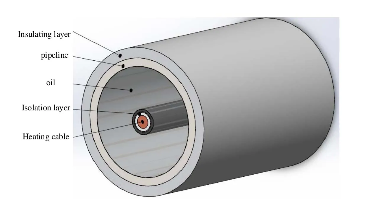
Figure 1:Built-in skin electric heating simulation model

Table 1:Material properties parameters
Through the heating cable in the oil pipeline, the ideal condition is the concentric position.Both the heating cable and the oil pipeline are loaded with 100 A and 200 Hz sinusoidal alternating current with equal and opposite directions.Set up the path with the center of the oil pipeline as the starting point and the insulation layer as the end point to draw the distribution curve of the magnetic induction B on the path, as shown in Fig.2.
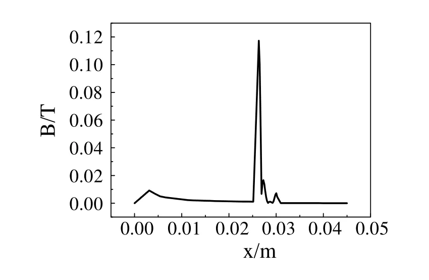
Figure 2:The distribution of magnetic induction intensity
It can be seen from the simulation that under the dual effects of skin effect and proximity effect, the magnetic field of the electric heat tracing system tends to concentrate on the inner surface of the oil pipeline.From the magnetic induction intensity distribution curve,the magnetic induction intensity at each point on the cross section of the oil pipeline can be quantitatively calculated.According to simulation results, the magnetic field distribution of the skin effect electric heat tracing system is mainly the internal distribution of the oil pipeline.
The magnetic field strength is known by solving the Bessel function H=aI0(x)+b K0(x),and according to the nature of the Bessel function, when r→0and x=kr→0, there are I0(x)=1,K0(x)→∞,H→0, it leads to b=0.When r=rd, there are x=krd,where rdis the diameter of the heat pipe, H0is the strength of the magnetic field at the surface of the pipe, so the magnetic field strength in the pipe is

It is advisable to take the micro-d r of the radius r in the pipe, and set the magnetic flux in the area of the above-mentioned micro-element torφ, then the magnetic flux through the whole pipe is

According to the nature of Bessel function [Wei, Wang and Li (1999)]

Find all the flux through the pipe

Perform rationalization on Eq.(8)

Where

Finally, you can get the total magnetic fluxφin the pipeline.
3 Establishment of built-in skin heating system model
From the perspective of electromagnetic field, the heating cable and oil pipeline in the built-in skin electric heating system are equivalent to the impedance, that is, Z=R+j X,where R is the sum of the intervention resistance of the oil pipeline and the heating cable.X is the sum of the interventional reactance of the oil pipeline and the heating cable.By solving the system total magnetic flux into the voltage of the equivalent circuit of the skin effect electric heat tracing system, can be assuming that the terminal voltage of the system is U, and its effective value is

From Eqs.(12), (13) and (14), the oil pipeline and heating cable in the skin effect electric heat tracing system can constitute an equivalent circuit model.The equivalent circuit model is shown in Fig.3.
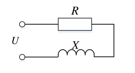
Figure 3: The equivalent circuit model
Since the heating cable radius is much smaller than the internal diameter of the oil pipeline, and the heating cable is a copper core wire, its relative magnetic permeability is 1 and the skin depth is large, and the skin effect of the heating cable itself can be ignored.Assume that the current frequency of the oil pipeline is f, the average value of the magnetic induction is , the diameter and length of the pipeline are D and L, the resistivity is ρ.The extent of the skin effect depends on the frequency and the characteristics of the material.The skin heating effect of the skin effect electric heat tracing system [Tang (1988)] can be obtained.

Substituting Eq.(9) into Eq.(15) can be obtained

Where k0.Since the heating efficiency of the built-in skin heating system is approximately 1, it can be assumed that the heating power of the builtin skin effect electric heating system is the amount of heat generated.According to the law of conservation of energy, the heat balance equation can be obtained, that is, the heat generated by the heating of the system is equal to the sum of the heat absorbed by the oil pipeline and the heat dissipated by the pipeline to the surrounding environment.That is,

Among them, G is the mass of heavy oil in the pipeline, C is the specific heat capacity of heavy oil, T is the difference between the working temperature of the pipeline and the initial temperature, and the built-in skin effect electric heat tracing heating power is the heat generated by the pipeline per unit time.Qoutis the amount of heat lost by the pipeline to the surrounding environment.That is,

Where K is the total heat transfer coefficient of the heavy oil flowing to the surrounding medium.Substituting Eq.(8) into Eq.(17) can be obtained

Applying the Laplace transform on both sides of Eq.(19) can obtain the relationship between the heating power and the pipeline temperature in the skin effect electric heat tracing system.

Because the temperature control has a strong hysteretic nature, the skin heating system is a large lag system, and the delay is expressed by a purely lagging link.Therefore, the system transfer function is expressed as follows

In summary, the skin-effect electric heating system introduces the intermediate variable power P, and the nonlinear relationship between the power P and the power frequency is obtained from the angle analysis of the electromagnetic field, and is represented by F(·),which is represented by Eq.(16).From the conservation of energy, the linear relationship between the power P and the pipe temperature is shown in Eq.(21).The entire system model consists of two modules connected in series, that is, a series connection of a nonlinear module and a linear module.The control domain calls this type of model a typical Hammerstein model.
4 Hammerstein model control strategy
4.1 Parameter identification
At present, the mathematical model of the system is derived from the mechanism of the skin effect electric heat tracing system, which is a Hammerstein model, as shown in Eq.(16) and Eq.(21).Although the order of the model has been determined, the parameters in the model are unknown, and the parameters in the model are related to the effective value of the input current of the system and the heating power P.It is necessary to identify the parameters in the model, which is also a prerequisite for the success of the control strategy.The Hammerstein model consists of a static nonlinear link and a dynamic linear link [Ding and Li (2003); Ding (2017); Ding, Zhang and Lin (2018)].Skin effect The Hammerstein model of the electric heat tracing system is shown in Fig.4.

Figure 4: The structure diagram of Hammerstein model
As can be seen from Fig.4, the Hammerstein model output of the skin effect electric heat tracing system can be expressed as

Where y (k) and e (k) are the system output and disturbance quantity, y0(k) and P (k) are the non-measurable intermediate variable, k0is the undetermined constants, f (k) is the current frequency of the system input pipe.G(z)=z-dB(z-1)/A(z-1), d is the system delay,B(z-1) and A(z-1) are all polynomials of the unit post-shift operator z-1, G(z) represents a classical Controlled Autoregressive Integral Moving Average (CARIMA) model.

Where naand nbare the order of A (z-1) and B (z-1).
In summary, Eq.(22) to Eq.(26) are Hammerstein models of the skin effect electric heat tracing system.Assuming that both f(k) and y(k) are zero at the initial stage, the input and output data are first collected, and then the appropriate system identification method is used to estimate the parameters of the skin effect electric heat tracing system.Since there are unmeasured intermediate variables for the parameters that need to be estimated in the skin effect electric heat tracing system, the system model information vector and the system model parameter vector are set using the key variable separation principle, and the auxiliary model is used to construct the auxiliary model of the linear module of the Hammerstein model [Jia, Yang and Qiu (2014)], as shown in Fig.5.

Figure 5: Considering the auxiliary model of Hammerstein model
The unmeasurable intermediate variables of the skin effect electric heat tracing system are replaced by the quantities in the auxiliary model, and the residual minimization criterion function is obtained.

The above minimization function is solved by an optimization algorithm to obtain the Hammerstein model parameters {k0, a1, b1, d} of the skin effect electric heat tracing system model.The reference pipe size in a certain pipeline project is taken as Φ62×4.5 mm, length is taken as 1000 m, thickness of insulation layer is 20 mm, inlet flow velocity of crude oil is 0.5 m/s, inlet temperature is 80°C.The deep seawater temperature is maintained at 4°C.The calculated total heat transfer coefficient between crude oil and seawater is K=1.74 W/(m2·K), and the crude oil mass flow rate is G=0.94 kg/s.The focus of this paper is not on the parameter identification of the Hammerstein model, so the process of identifying the Hammerstein model is not described in detail.The sample data collected using standard particle swarm optimization algorithm to identify and optimize the Hammerstein model.The identification parameters are set to window width L=100,particle number N=20, inertia weight w(t)=0.9-0.5 t/Nmax, learning factor parameter initial value c1=c2=0.15, search precision to 0.01, and the maximum evolutionary generations is Nmax=1000, parameters after multiple simulations are shown in Tab.2.

Table 2:When the interference of noise, different identification results
Thus, the Hammerstein model of the built-in skin effect electric heat tracing system is determined.

At present, the Hammerstein model is mostly focused on the research of identification,and there is not much research on its control strategy [Gao (2016)].This article focuses on the study of the control strategy of the Hammerstein model of the skin effect electric heating system.
4.2 ADRC for hammerstein model of skin effect electric heat tracing system
ADRC uses the integral-series tracker to extract reasonable differential signals, and uses appropriate non-linear combinations to improve PID control and improve its adaptability and robustness.In order to facilitate the application in the field of engineering, American scholar Gao [Gao (2003)] proposed the concept of frequency scaling to simplify the nonlinear ADRC into a linear ADRC structure.It has been proved by a large number of experiments and studies that linear ADRC can also achieve good control effects, and all parameters of ADRC become a function of bandwidth.The simplification and parameterization make the physical meaning more intuitive and become more suitable for engineering applications.The essence of the linear ADRC implemented in the actual control system is to construct an Extended State Observer (ESO), and the ESO mainly implements real-time estimation of the sum of the internal interference and the external interference in the system.To realize discretization of linear ADRC, the essence is to convert linear ESO into Current Discrete Extended State Observer (CDESO) [Huang, Du and Zheng (2017)].
4.2.1 Implementation of CDESO
For the sake of simplicity, consider second order plant as

Where u and y are the input and output, coefficient a1, a2are unknown, and w is an external disturbance, it is unknown too, but the part of b is known.The system is rewritten as


Where, L is column vector, which should make (A-LC) stable.The following relationship can be derived from Eq.(33).

The analytical solution of the above equation is z(t)− x(t)=e(A−LC)(t−t0)[z(t0)−x(t0)],because (A-LC) is stable, it can be seen that[z(t)− x(t)]=0.In this way, the observed state can approach the state of the original system.Where z→x , z is the observer state vector, L is determined by placing the poles of the characteristic equation in one location(-ωo, ωois the observer bandwidth).

The state space model in Eq.(32) is first discretized by applying ZOH [Miklosovic,Radke and Gao (2006)].


where, ud(k)=[u(k) y(k)]Tis the combined input of discrete observer, yd(k) is the discrete observer output, ΦE=[Φ-ΦLcH], ГE=[Г ΦLc], HE=[I-LcH], JE=[0 Lc], and the current estimator gain vector Lcis determined by placing the poles of the discrete characteristic equation in β.

The relation between the discrete estimator poles and the continuous observer poles is given as

After the above analysis, each coefficient matrix in the discrete observer can be obtained.

ESO is the core part of ADRC, which is used to solve disturbance observation problems.According to the idea of state observer, the total disturbance is expanded into a new state variable.Then, the input and output of the system are used to observe all the states including the original state and disturbance of the system.
4.2.2 Temperature control based on auto disturbance rejection control technology
Because the built-in skin heating system is a time-varying, large-lag nonlinear system and is influenced by many factors such as the environment, the composition of the fluid in the tube, the flow velocity, the temperature, etc., we are not likely to know its precise mathematical model.Researcher Han [Han (2009)] hoped to get rid of the constraints of mathematical models, to find the disturbances and uncertain disturbances in the process or system, and to actively extract the disturbance information from the input/output signals of the controlled object before the disturbance obviously affects the final output of the system.Then, as soon as possible, the control signal is used to eliminate it, so as to achieve the balance of physical quantity, then the model-independent ADRC technology emerges as the times require [Zhu (2017)].In this paper, the Hammerstein model-based electric heat tracing system is used to obtain the intermediate variables using the ADRC of the linear model, and then the intermediate variable is input to the improved nonlinear static gain to inversely calculate the actual control input.The ADRC block diagram of the skin effect electric heat tracing system based on the Hammerstein model can be shown in Fig.6.

Figure 6:ADRC control block diagram
In the system block diagram, yris the system set value, P is the control quantity, y is the actual output, and z1, z2, and z3are the observer outputs.To simplify controller parameters, define b0as the compensation factor and ωcas the controller bandwidth.Since the ESO can estimate and compensate external disturbances and internal disturbances in real time, static errors of constant values can be eliminated.For the builtin skin effect electric heat tracing system, the linear feedback control law of ADRC is expressed as follows

In Eq.(40), kpand kdare the parameters of the linear feedback control law, where kp=,kd=-2ωc, and the final control input is expressed as follows

It is not difficult to find out from the above design steps that the parameters of the discrete-time linear ADRC only need to adjust the observer bandwidth ωo, the controller bandwidth ωcand the compensation parameter b0, which greatly reduces the workload of the engineering setting.After solving the intermediate variable power P, the next task is to inversely control the power supply frequency f according to the nonlinearity Eq.(16)of the Hammerstein model.Researchers have proposed many solutions to this problem.There are first and second approximate solutions [Xu and Mao (2000)].There is a method of changing the nonlinear link to the intermediate variable to obtain the control amount [Liu (2007)].There is also an inverse system that incorporates a nonlinear part in front of the Hammerstein model, rendering the entire system a pseudo-linear system approach [Huang, Lei and Li (2009)].For the nonlinear relationship between the power frequency and the heating power in the built-in skin effect electric heat tracing system,the current frequency and the heating power are both greater than zero, so there must be a unique inverse function F(·) of F(·)-1.From this we can directly solve the equation to calculate the control quantity f.That is, the heating power required to be controlled is first solved by the heating temperature required in the linear link of the built-in skin electric heating system, and then, the power frequency in this condition is inversely solved by the nonlinear link to achieve accurate heat tracing effect.
5 Simulation verification
In order to verify the feasibility and effectiveness of ADRC in the built-in skin electric heat tracing system, a simulation experiment was carried out.The Hammerstein model of the built-in skin heating system is known to have the nonlinear and linear links as Eq.(16)and Eq.(21), respectively.There is a one-to-one correspondence between power frequency and heating power, so it is deduced that F(·) has a unique inverse function F-1(·)=1.49P (k)1/2.According to the linear link type Eq.(21), ADRC is used to obtain the intermediate variable P.The controller parameters are:sampling period h=10 s,b0=0.0023, and controller bandwidth ωc=0.35.Because the system adjustment time is slightly larger, so that let ωo=2ωcbe ωo=0.7, so the discrete observer CDESO coefficient matrix β=0.001, which can be constructed according to Eq.(39) discrete observer.The simulation time is 2000 s, and the given reference input tracing temperature is 80°C.In addition, add a perturbation of D(z)=1+0.5z-1to the input port, design the ADRC controller to simulate according to the above parameters, and obtain the simulation curve as shown in Fig.7 and Fig.8.
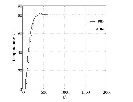
Figure 7:System output response curve
Fig.7 shows the output of the system and compares the control effects of PID and ADRC.Under a given disturbance, the system output remains in a stable state with only slight fluctuations.However, the ADRC dynamics are significantly better than the PID control.Under the action of the ADRC, the dashed line in Fig.8 represents the value of the system control power supply frequency f, and the solid line is the value of the system intermediate variable heating power P.As can be seen from the above figure, when the system power frequency is 200 Hz, the heat tracing temperature of the skin effect electric heating system is maintained at 80°C.In order to fully demonstrate that the ADRC can be independent of the object model, the disturbance caused by the tracking error is eliminated in time by observation.Since the inlet velocity of heavy oil is closely related to the system model parameters, the flow rate increases, the model parameter a1increases,and b1decreases, which cause the linear part of the Hammerstein model to change, thus changing the object model as a whole.It is possible to select the inlet flow rates of heavy oils to be 0.3 m/s, 0.5 m/s and 0.8 m/s, respectively.Only the flow rate is changed, and the controller setting parameters remain unchanged.The control curves at different flow rates are plotted by simulation, as shown in Fig.9.
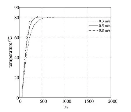
Figure 9:System output response curve with different heavy oil inlet velocity
As can be seen from Fig.9, as the flow rate increases, the longer the target heating temperature is reached.This is because the heat generated by the electric heat tracing system is not transmitted to the heavy oil in the pipe in time, so that the temperature rises slowly.However, for different heavy oil inlet flow rates, the values of ωc, ωoand β in the ADRC are the same, and the outlet temperature of the pipe can reach 80°C.The system can still maintain the steady state under the given interference at the output, indicating that the system has strong anti-interference ability.The results show that ADRC can tolerate the unknown dynamic changes of the system to a large extent with certain system model information.
5 Concluding remarks
Due to the working environment in which the built-in skin electric heat tracing system and the heat-receiving medium are time-varying, and the temperature control has the characteristics of nonlinearity, large inertia, hysteresis, etc.so it is difficult to establish its accurate mathematical model, which makes it difficult to achieve precise control and energy saving of the built-in skin electric heating system.This paper analyzes the mechanism of the built-in skin-heating electric heating system, obtains the magnetic field distribution of the skin-effect electric heat tracing system, and obtains the equivalent circuit model of the built-in skin-heating electric heat tracing system through the mechanism modeling.The intermediate variable heating power is introduced to establish the relationship between the power frequency and the skin effect heat tracing temperature,and the built-in skin heating system is Hammerstein model as a whole.Then combined with the experimental data of the system, the standard particle swarm optimization algorithm is used to identify and optimize the model parameters.Finally, the DLADRC is designed based on the identification model, and the feasibility and effectiveness of the ADRC strategy are verified by simulation.It provides an effective way for the reliable operation of the skin effect electric heat tracing system.
Acknowledgement:This study was also financially supported by “the Fundamental Research Funds for the Central Universities” (No.16CX06051A).In addition, this work is supported by the Key Program of Shandong Provincial Major research and development plan Foundation, China (No.2016GGX103031).
 Computer Modeling In Engineering&Sciences2018年11期
- Computer Modeling In Engineering&Sciences的其它文章
- Pose Estimation of Space Targets Based on Model Matching for Large-Aperture Ground-Based Telescopes
- On the Robustness of the xy-Zebra-Gauss-Seidel Smoother on an Anisotropic Diffusion Problem
- A Shaft Pillar Mining Subsidence Calculation Using Both Probability Integral Method and Numerical Simulation
- A Virtual Boundary Element Method for Three-Dimensional Inverse Heat Conduction Problems in Orthotropic Media
- Kautz Function Based Continuous-Time Model Predictive Controller for Load Frequency Control in a Multi-Area Power System
- Individualized Design of the Ventilator Mask based on the Residual Concentration of CO2
