
A Simple,Compact and Rigid Scanning Tunneling Microscope
2018-11-09 06:53:38WeifengGeJihoWngYuinHouQingyouLuc
Wei-feng GeJi-ho WngYu-in HouQing-you Luc
a.Hefei National Laboratory for Physical Sciences at the Microscale,University of Science and Technology of China,Hefei 230026,China
b.Anhui Province Key Laboratory of Condensed Matter Physics at Extreme Conditions,High Magnetic Field Laboratory of the Chinese Academy of Sciences,Hefei 230031,China
c.Collaborative Innovation Center for Artificial Microstructure and Quantum Control,Nanjing University,Nanjing 210093,China
Key words:Scanning tunneling microscope,Sapphire guiding tube,Finite element analyses,Atomic-resolution image
I.INTRODUCTION
The scanning tunneling microscope(STM)has become a powerful tool to investigate the electronic structure of material surfaces in real space at atomic resolution since it was invented by Binniget al.and Rohreret al.[1,2].However,it is extremely sensitive to external vibrations because the tunneling current is exponentially dependent on the tip-sample distance when the tunneling junction forms[3].In order to make the STM highly immune to external vibrations and enhance its mechanical stability,the eigenfrequency of the STM body should be as high as possible.Higher eigenfrequency means that it is not easy to be excited by external vibrations,thus the in fluence of perturbations on the tip-sample junction caused by mechanical vibrations can be reduced when scanning images.To this end,the STM design should be compact,rigid and highly symmetric in structure as much as possible[4].Until now,a lot of compact and stable STMs have been developed by optimizing the geometry of the STM structure,including the most frequently used Pan-style[5]and the Besocke-style[6,7]STMs.Although the former is a rigid design in which six shear piezoelectric legs grab a triangular or hexagonal shaft that holds a scanner,it is rather complicated to build and its radial dimension is also difficult to minimize to fit some narrow space.The latter,however,adopts an inertial coarse motor where three stepping piezotubes are located on a ramp only by gravity,which reduces the mechanical rigidity of the STM.Therefore,how to build a simple,compact and rigid STM with a high stability is still a great challenge.In this work,we will present the design and construction of a novel STM in which the scan unit only consists of a sapphire guiding tube and a spring-clamped square rod that holds a piezotube scanner.The sti ffsapphire guiding tube used here forms a short tip-sample mechanical loop which not only simplifies the complexity of the STM structure,but also greatly improves the rigidity and stability of the STM body.Besides,the in fluence of thermal drift can be reduced by using the highly symmetric sapphire guiding tube which has a good thermal conductivity.To maintain the overall design compact(16 mm in diameter and 63 mm in height),the coarse approach is driven using a SpiderDrive piezoelectric motor[8].With the compact and rigid STM,we have successfully achieved clear atomic-resolution images in air at room temperature.Also the compact design and the excellent performance allow it to be used in some extreme conditions,such as ultrahigh vacuum,ultralow temperature,and high magnetic field,etc.in future applications.
II.STM HEAD DESIGN
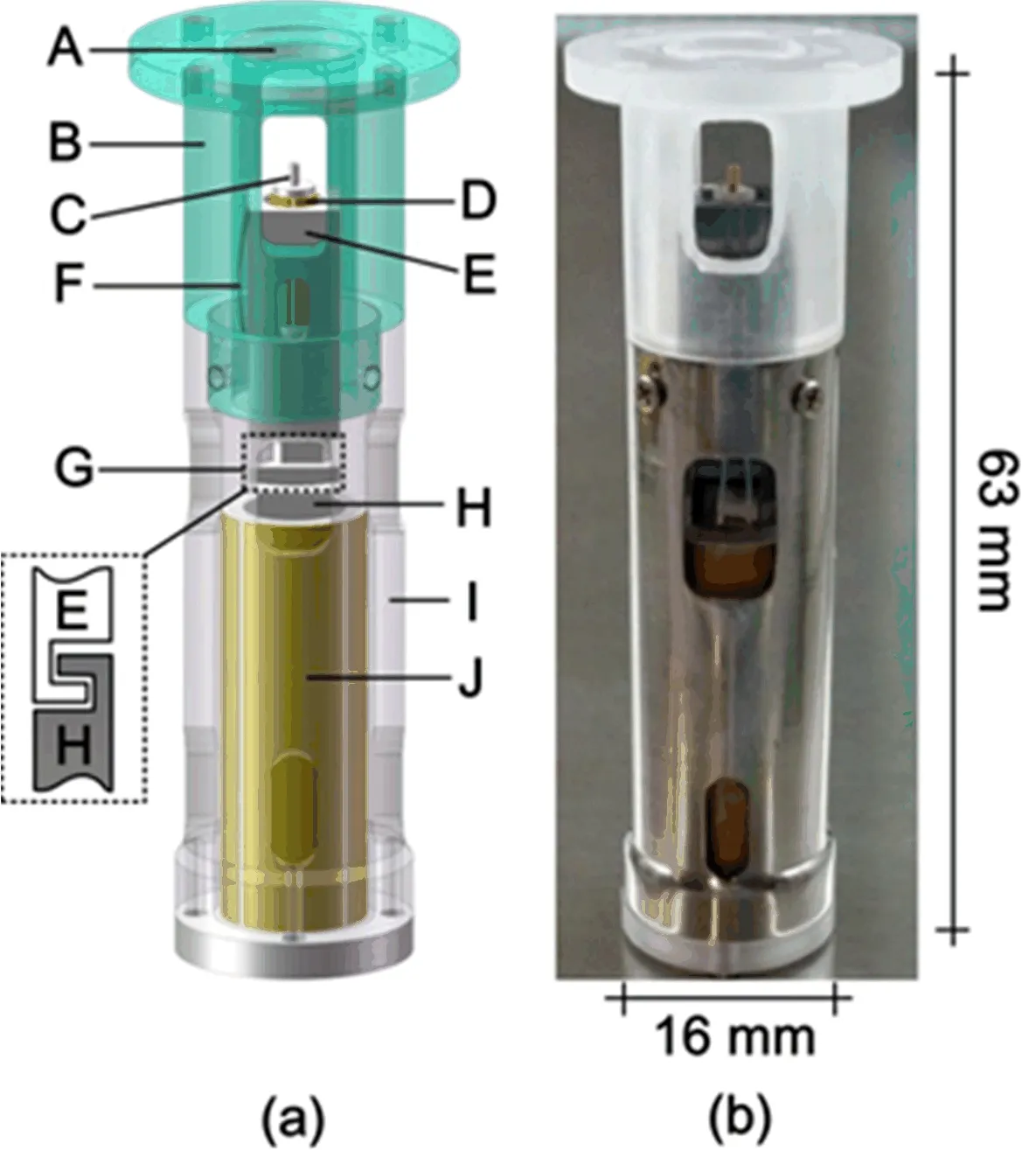
FIG.1(a)Schematic illustration of the STM head.A:receptacle for sample holder,B:sapphire guiding tube,C:tip holder,D:piezotube scanner(free end),E:square rod,F:spring strip,G:a pair of hooks,H:driving shaft,I:tubular frame,J:SpiderDrive.(b)Photograph of the STM head.
A schematic drawing and a photograph of our homebuilt STM head are shown in FIG.1(a)and(b),respectively.The scan unit consists of a sapphire guiding tube(B,whose inner wall is well polished)and a square rod(E,made from tantalum)that holds a tiny piezotube scanner(D,with 3.2 mm outer diameter,0.5 mm wall thickness and 7 mm length;EBL3 type,EBL Products Inc.).The square rod fits into the guiding tube well with two edges contacting with the inner wall of the tube.A bent spring strip(F)is then inserted into the gap between the square rod and the guiding tube so that the rod is spring held.The upper end of the square rod contains a deep hole to accommodate the piezotube scanner,while the opposite end has a hook to connect with the driving shaft(H,with a matched hook at upper end)of the coarse motor SpiderDrive(J,the moving part of the motor is the driving shaft H that moves in vertical direction,see Ref.[8]for more details).The sapphire guiding tube used here actually serves as a rail for the square rod.The square rod carrying the scanner,driven by the driving shaft of the SpiderDrive from below via a pair of hooks(G),can slide smoothly inside the guiding tube,thus implementing the coarse approach process.Note that the sapphire guiding tube,the SpiderDrive and the tubular frame(I)should be mounted as coaxially as possible to guarantee the smooth sliding for the square rod.A small segment of metal capillary tube(with 0.7 mm outer diameter by 0.3 mm inner diameter)is used as the tip holder(C)which is mounted at the free end of the scanner.The tip is inserted into the capillary tube and typically held by friction.The sample is glued on a sample holder which can then be loaded to the receptacle(A)from top while facing the free end of the scanner.
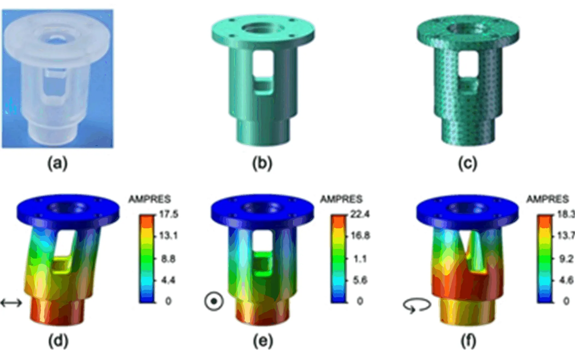
FIG.2(a)Photograph and(b)3D model of the sapphire guiding tube,respectively.(c)Model with mesh for finite element analyses.(d)−(f)Simulated resonance pattern of the guiding tube( fixed at the upper end):(d)and(e)correspond to the bending vibration mode with resonance frequencies of 26053 Hz and 30909 Hz,respectively;(f)corresponds to the torsional vibration mode with a resonance frequency of 53780 Hz.The color scale bars show the amplitude of resonance.The material properties for finite element analyses are as follows:density of 3.98 g/cm3,shear modulus of 145 GPa,Young’s modulus of 345 GPa,Poisson ratio of 0.28.
In conventional STM designs,the tip(or sample)scanner is fixed directly to the coarse motor to approach the sample(or tip)[5−7].In this case,the instability of the coarse motor caused by factors such as external vibration,intrinsic stress,thermal drift,and electric noise is inevitably transferred into the tip-sample loop,thus downgrading the stability of the STM[9].In our design,the square rod can be slightly detached from the driving shaft of the Spiderdrive if the pair of hooks(G)is hooked loosely.The operation details are as follows.The square rod carrying the piezotube scanner,as mentioned above,is pushed by the driving shaft of the SpiderDrive during coarse approach.When the coarse approach process is done,the driving shaft can be withdrawn slightly from the square rod by applying reverse voltage signals to the SpiderDrive,thus not in touch with the square rod(including the scanner)during imaging time.The superiority of this design is that the instability of the coarse motor can hence be prevented from entering the tip-sample junction when scanning images.In addition,since there is no coarse motor involved,the tip-sample mechanical loop in the design becomes short which can further enhance the stability of the STM.
To improve the rigidity and stability of the STM body,the choice of materials is also very important besides the optimization for the structure geometry.In the scan unit,the guiding tube is a key component part that forms the tip-sample mechanical loop.Therefore,a sti ffguiding tube,such as a sapphire tube,can contribute to the rigidity enhancement of the STM body.Also the material of sapphire has a good thermal conductivity to reduce the thermal drift when the STM is used in low temperature conditions.So the guiding tube was machined from a piece of single-crystalline sapphire and we have performed finite element analyses of the 3D model of the guiding tube(FIG.2).It was found to show extremely high resonance frequencies in three vibration modes(including two bending modes and one torsional mode)as shown in FIG.2(d−f).High eigenfrequency of the guiding tube improves the rigidity of the STM body significantly to resist external disturbances,thus enhancing its mechanical stability.
III.CONTROL SYSTEM DESIGN
To perform the coarse approach and image scan,we use a custom-built controller for the STM.FIG.3 shows the control system architecture.The basic electrical control unit(ECU)was constructed using a PXI Chassis(PXI-1082Q)from National Instruments[10]that was equipped with an embedded controller(PXI-8108)and a data acquisition card(PXI-7851R).The controller uses a real-time operating system that absolutely guarantees reliable task execution with very precise timing.The card integrates eight analog outputs and eight analog inputs using field-programmable gate array(FPGA)technology to provide the necessary electrical signals.The two output signals(AO1−AO2)are adjusted to form two pairs of push-pull signals,respectively,which are then applied to the outer electrodes of the piezotube scanner for XY scan. The five output signals(AO3−AO7)are passed through a high-voltage amplifier with a 13×gain.In this case,signal AO3is applied to the inner electrode of the scanner for Z scan,while signals AO4−AO7are applied to the piezoelectric motor(SpiderDrive)for the coarse approach.The tunneling current obtained is magnified using a home-built preamplifier(indicated by the dashed box in FIG.3)[11].In imaging mode,the input signal(AI1)from the preamplifier is collected to acquire STM images while the tip is scanning over the sample surface at a fixed bias voltageVbias.The ECU is addressed over a transmission control protocol/Internet protocol(TCP/IP)connection using a master software that runs on a personal computer.The software was written in-house in LABVIEW.
IV.PERFORMANCE
To demonstrate the performance of the STM,we scanned the topography of high oriented pyrolytic graphite(HOPG,grade SPI-2 from Structure Probe,Inc.)which is an ideal sample for scanner test and calibration.The sample was cleaved using a piece of scotch tape to obtain a fresh and flat surface before experiments,and the tip was mechanically cut from a 0.25-mm-thick Pt80/Ir20 wire(from Goodfellow Cambridge Ltd.).FIG.4 shows the constant height STM images of graphite obtained in ambient conditions.The bias voltage applied on the probe tip was 100 mV with the sample grounded.The scan rate was 6 lines per second.It is clearly seen that these atomic-resolution images are very smooth and exhibit highly symmetrical hexagonal arrangement,indicating the excellent stability of the STM.Below the STM images,smooth cross-sectional pro files taken along the scan direction illustrate the lownoise performance of the STM.The high performance of the STM,based on the results,is mainly due to its compact and rigid design by optimizing the geometry structure and choice of materials.
V.CONCLUSION

FIG.4 Atomic-resolution STM images(raw data)of graphite taken in ambient conditions.The scan range are:(a)4.5 nm×4.5 nm,(b)3 nm×3 nm,(c)1.5 nm×1.5 nm,(d)0.75 nm×0.75 nm.
We presented a novel STM design featuring simplicity,compactness and rigidity.The core component part is the sti ffsapphire guiding tube in which a springclamped square rod carrying the piezotube scanner can slide smoothly for coarse approach driven by a SpiderDrive.Performance and stability of the STM were demonstrated by high quality atomic-resolution images of graphite.Due to its compactness and rigidity,the STM can also be used in some extreme conditions such as ultra-high vacuum,ultra-low temperature and high magnetic fields.
VI.ACKNOWLEDGMENTS
This work was supported by the National Key RD Program ofChina(No.2017YFA0402903and No.2016YFA0401003),National Natural Science Foundation of China(No.21505139,No.51627901,and No.11374278),and Chinese Academy of Sciences Scientific Research Equipment(No.YZ201628),National Science Foundation for Young Scientists of China(No.11504339).
[1]G.Binnig,C.Gerber,E.Weibel,and H.Rohrer,Phys.Rev.Lett.50,120(1983).
[2]G.Binnig and H.Rohrer,Rev.Mod.Phys.59,615(1987).
[3]G.Binnig,H.Rohrer,C.Gerber,and E.Weibel,Phys.Rev.Lett.49,57(1982).
[4]C.R.Ast,M.Assig,A.Ast,and K.Kern,Rev.Sci.Instrum.79,093704(2008).
[5]S.H.Pan,E.W.Hudson,and J.C.Davis,Rev.Sci.Instrum.70,1459(1999).
[6]J.Frohn,J.F.Wolf,K.Besocke,and M.Teske,Rev.Sci.Instrum.60,1200(1989).
[7]S.J.Ball,G.E.Contant,and A.B.McLean,Rev.Sci.Instrum.75,5293(2004).
[8]H.B.Zhou,Z.Wang,Y.B.Hou,and Q.Y.Lu,Ultramicroscopy 147,133(2014).
[9]Q.Wang,Y.B.Hou,J.T.Wang,and Q.Y.Lu,Rev.Sci.Instrum.84,113703(2013).
[10]http://www.ni.com/zh-cn.html.
[11]Q.F.Li,Q.Wang,Y.B.Hou,and Q.Y.Lu,Rev.Sci.Instrum.83,043706(2012).
 CHINESE JOURNAL OF CHEMICAL PHYSICS2018年5期
- CHINESE JOURNAL OF CHEMICAL PHYSICS的其它文章
- Extraction of Lignin from Tobacco Stem using Ionic Liquid
- Gd Doped Hollow Nanoscale Coordination Polymers as Multimodal Imaging Agents and a Potential Drug Delivery Carriers
- 3D Macro-Micro-Mesoporous FeC2O4/Graphene Hydrogel Electrode for High-Performance 2.5 V Aqueous Asymmetric Supercapacitors
- Gamma Ray Radiation Effect on Bi2WO6Photocatalyst
- Ag-Cu Nanoparticles Supported on N-Doped TiO2Nanowire Arrays for Efficient Photocatalytic CO2Reduction
- UV Laser Regulation of Surface Oxygen Vacancy of CoFe2O4for Enhanced Oxygen Evolution Reaction