
Multi-Physics Modeling Assisted Design of Non-Coking Anode for Planar Solid Oxide Fuel Cell Fueled by Low Steam Methane
2018-11-09 06:53:28JiangZhuBaoxuanWangZijingLin
Jiang ZhuBao-xuan WangZi-jing Lin
Hefei National Laboratory for Physical Sciences at the Microscale&CAS Key Laboratory of Strongly-Coupled Quantum Matter Physics,Department of Physics,University of Science and Technology of China,Hefei 230026,China
Key words: Carbon activity,Methane steam reformation,Diffusion barrier layer,Fuel utilization ratio,Non-coking condition
I.INTRODUCTION
The ability to use methane as fuel is a strong advantage of solid oxide fuel cells(SOFCs)as methane is abundant in nature.Internal methane steam reforming(MSR)is very appealing as it is helpful for increasing the system efficiency and reducing the system complexity[1–4].To reap the full bene fit of internal MSR operations,however,using methane with low steam content as the fuel is required so that the consequence of reduced power density and increased heating requirement with high steam content fuel may be prevented[5,6].
To realize the use of low steam methane fuel,materials to avoid anode coking are critically important and are actively pursued[3–14].A common approach to avoid anode carbon deposition is to eliminate the use of Ni in the anode[5–10].Alternatively,methods of modifying the Ni containing anode with coking resistant material are developed[4,11–15].Unfortunately,there are serious drawbacks associated with all the known material designs of coking resistant anode,e.g.,low electronic conductivity,poor chemical compatibility with other cell components and high material cost[4,15].
Interestingly,there have been numerous reports of stable direct-methane operation with the well-known Ni-based anodes,despite the high propensity of Ni to carbon deposition[16–22].Recent studies suggest two likely explanations for this apparent discrepancy[16,17,23].First,some stable operations are observed because that the methane pyrolysis kinetics on Ni are relatively slow for working temperature<700◦C.Second,others are due to the coking suppression effect of SOFC operation.Specifically,it is observed that the naturally occurring soot formation disappears when the output current density is above a critical value[24].The coking suppression effect may be explained by the steam production in the current generation that dilutes the local methane fuel[22,23].Both the explanations share the same mechanistic feature that the anode coking is kinetically controlled.In fact,the kinetic nature of the soot formation phenomenon is easy to conclude as coking is not observed at some thermodynamically favorable domain.The dynamic feature of the soot formation points out the possibility of achieving coking free operation with low steam methane by anode structural design and selection of operating parameters.
Indeed,experiments have shown that the critical density current for coking free operation may be reduced by adding a diffusion barrier layer on the anode[24].The result is interesting and important,but is limited in two substantial ways.First,the existing studies are conducted on button cells only.It is unclear how to ap-ply the result to production size SOFCs.Second,the result is qualitative in nature.While it shows a proof of concept,no specific practical design guideline is given.For example,the relationships between the thickness of diffusion barrier layer and the critical current density as well as the cell performance are unclear.In short,there is a lack of study on the design of diffusion barrier layer for coking free operations of SOFCs fueled by low steam methane.Considering the bene fits of high power density and high energy efficiency associated with the low steam methane fuel,such studies are highly important for the development of SOFC technology.
This work addresses the anode design issue through multi-physics modeling.Based on simulations of relevant experiments,a kinetic criterion of non-coking condition is deduced.Parametric studies are then carried out to examine the effects of operating condition and anode design on the SOFC performance and the likelihood of soot formation.A rule of anode diffusion barrier layer design for the optimal balance of operating conditions and cell performance is found for the non-coking operations of low steam methane fuel.
II.METHOD
A.Multi-physics modeling
A multi-physics model with a rigorous consideration of the balance of local electrochemical potentials is used for the numerical simulations of methane fueled SOFCs.The electrochemical reaction,chemical reaction,electrical conductions,gas transport and heat conduction are fully coupled in the model.Such a multi-physics model has been described in detail in Refs.[25,26].A standard set of SOFC materials,YSZ electrolyte,Ni-YSZ anode and YSZ-LSM cathode,are assumed here.These materials are chosen because they coincide with those used in experiments examining CH4fueled SOFCs[16,24,27,28].Parameters for the material properties and electrode microstructures are referred to Refs.[22,24,26].When comparing with experiments,geometric models of SOFCs are built according to the experimental specifications.When discussing the diffusion barrier layer designs,a planar SOFC with coflow gas con figuration and a channel length of 10 cm for the electrochemically active area is assumed.The microstructural parameters of the barrier layer for gas diffusion are:25%for the porosity,the tortuosity of 3.8,and the average pore radius of 0.25µm.Other material properties such as the electronic and thermal conductivities of the barrier layer are the same as that of the anode.Notice,however,the barrier layer is MSR inert.
When considering the anode design,the operating temperature is set atTop=1073 K considering the propensity of carbon formation increases with the temperature and an operating temperature above 1073 K is undesirable in practice.The operating cell voltage,Vop,is set at 0.8 V,unless specified explicitly otherwise,asVopis expected to be below 0.8 V in practice.Non-coking condition satis fied forVop=0.8 V is automatically satis fied forVop<0.8 V due to the increased current associated with the reducedVop.The exit fuel and air pressures are both set at 1 atm.The input fuel consists of 3mol%of H2O.Such a fuel can be easily realized by bubbling CH4through water at around the room temperature.
The coupled multi-physics equations are solved by the commercial finite element software,COMSOL MULTIPHYSICSrVersion 3.5[29].
B.Carbon activity criterion for soot formation
According to the thermodynamics principle,carbon deposition occurs when the overall carbon activity(aC)is larger than one[30–34].The model for the carbon activity concerning MSR catalyzed by Ni as suggested in Ref.[32]is used here.The model is chosen as it is consistent with the elementary step analysis of MSR via a pseudo-steady-state analysis and assuming that chemisorbed carbon(C∗)and activated catalyst atom are the most abundant reactive intermediates[32,33].In this model,aCis expressed as[32]:
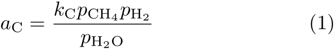
wherekCis a temperature dependent constant.piis the partial pressure of gas speciesi(i=CH4,H2,H2O).As the methane decomposition is likely the major source of C∗,kC(oraC)should be proportional to the methane decomposition rate.That is,Eq.(1)may be rewritten as,
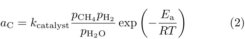
whereEa=96.1 kJ/mol is the activation energy of methane decomposition,as determined experimentally[35].kcatalystis a constant depending on the catalyst morphology. For the standard anode material used,comparison between theory and experiment yieldskcatalyst=9400 bar−1,as to be seen below.
C.Methane steam reforming kinetics
The reaction rate of MSR,CH4+H2O=CO+3H2,as catalyzed by Ni is usually expressed as,
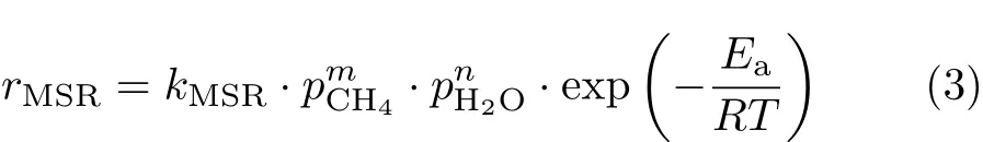
The commonly accepted value for the methane reaction order,m,is 1.The steam reaction order,n,is dependent on the steam carbon ratio,S/C.nis known to be 1 for low S/C[26,36].Andnis close to 0 for high S/C[35,37].Combining the results of Ref.[35]and Ref.[26],representative of low and high S/C,respectively,a unifying expression for the MSR reaction rate is deduced as,
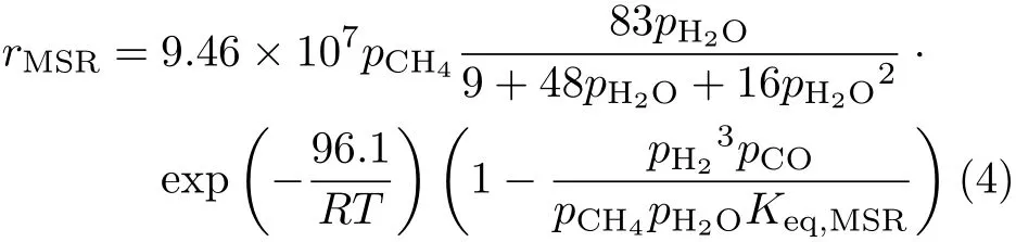
whereKeq,MSRis 1.198×10¹⁷
Eq.(4)is used in this work,unless explicitly stated otherwise.Considering the in fluence ofrMSRon the result ofaC,a few other reaction rate expressions often seen in literatures[30,36,38–40]are also used for testing purpose,including:

Hereciis the molar concentration of fuel speciesi(i=CH4,H2O,CO,and H2O).The value of¯kis determined by fitting the experimental open circuit voltage atT0=1073 K[16,28].The resulting¯kvalues are 350,20 and 1.05×10⁸for Eq.(5),Eq.(6),and Eq.(7),respectively.
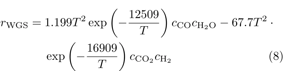
Following the recommendation of Ref.[30],the reaction rate for the near equilibrium water-gas shift(WGS)reaction,CO+H2O=CO2+H2,is expressed as,
III.RESULTS AND DISCUSSION
A.I-V curves and carbon activity criterion
By constructing button cell geometric models and using operating conditions specified experimentally[24],simulations with the above mentioned multi-physics model are carried out to determine theI-Vrelations and distributions of physical quantities.FIG.1 compares the theoretical and experimentalI-Vresults.Clearly,the theoretical results for different operating temperatures and different anode structures(with and without barrier layer)are in very good agreement with the experimental data,demonstrating the validity of the modeling tool used.

FIG.1 Comparison of theoretical and experimental[24]I-V relations of button cell SOFCs with and without a 400µmthick anode diffusion barrier layer.SOFCs are fueled by humidified methane(H2O:CH4=3:97).
The distributions of partial pressures of gas species are used to computeaCof Eq.(2).It is known experimentally that the critical current density of non-coking operation atTop=1073 K is 0.6 A/cm2with a barrier layer thickness of 400µm and is less than 1.8 A/cm2when there is no barrier layer[24].By requiringaCin the entire anode to be less than 1 for the non-coking current density,the maximum possiblekcatalystthus determined is 9400 bar−1.
B.Mechanism for the reduction of carbon activity
As indicated in Eq.(2),the carbon activity is ultimately determined by the distributions of fuel species in the Ni-YSZ anode.As the current generation requires the consumption of CH4and the production of H2O,the effect of operating current on the reduction of carbon activity is in principle easily understandable(Eq.(2)).To illustrate the role of diffusion barrier layer on reducing the carbon activity,FIG.2 compares the partial pressures of fuel species in the anode near the fuel inlet and along the anode thickness direction for operating SOFCs with and without a diffusion barrier layer.The anode near the fuel entrance is chosen as it is where the highest carbon activity is found for the operating SOFC examined.As shown in FIG.2,relative to the cell with a bare Ni-YSZ anode,the diffusion barrier layer reducespCH4while increasespH2Oinside the Ni-YSZ zone.This is simply because that the barrier layer makes it difficult both for H2O to diffuse away from the Ni-YSZ zone and CH4to diffuse into the Ni-YSZ zone.As a result,the critical current density for coking free operation is reduced by the presence of a diffusion barrier layer.
In addition to being affected by the processes of current generation(CH4consumption and H2O production)and gas diffusion(anode thickness and barrier layer),the fuel species are first of all dependent on the input fuel and the overall fuel consumption,i.e.,fuel utilization.For givenVopandTop,the fuel utilization is dependent on the amount of fuel supplied.That is,the carbon activity is dependent on the fuel flow rate for the chosenVopandTop.To illustrate,FIG.3 shows the dependence of the maximum value of carbon activity in the anode,together with the fuel utilization ratio,on the fuel flow rate.
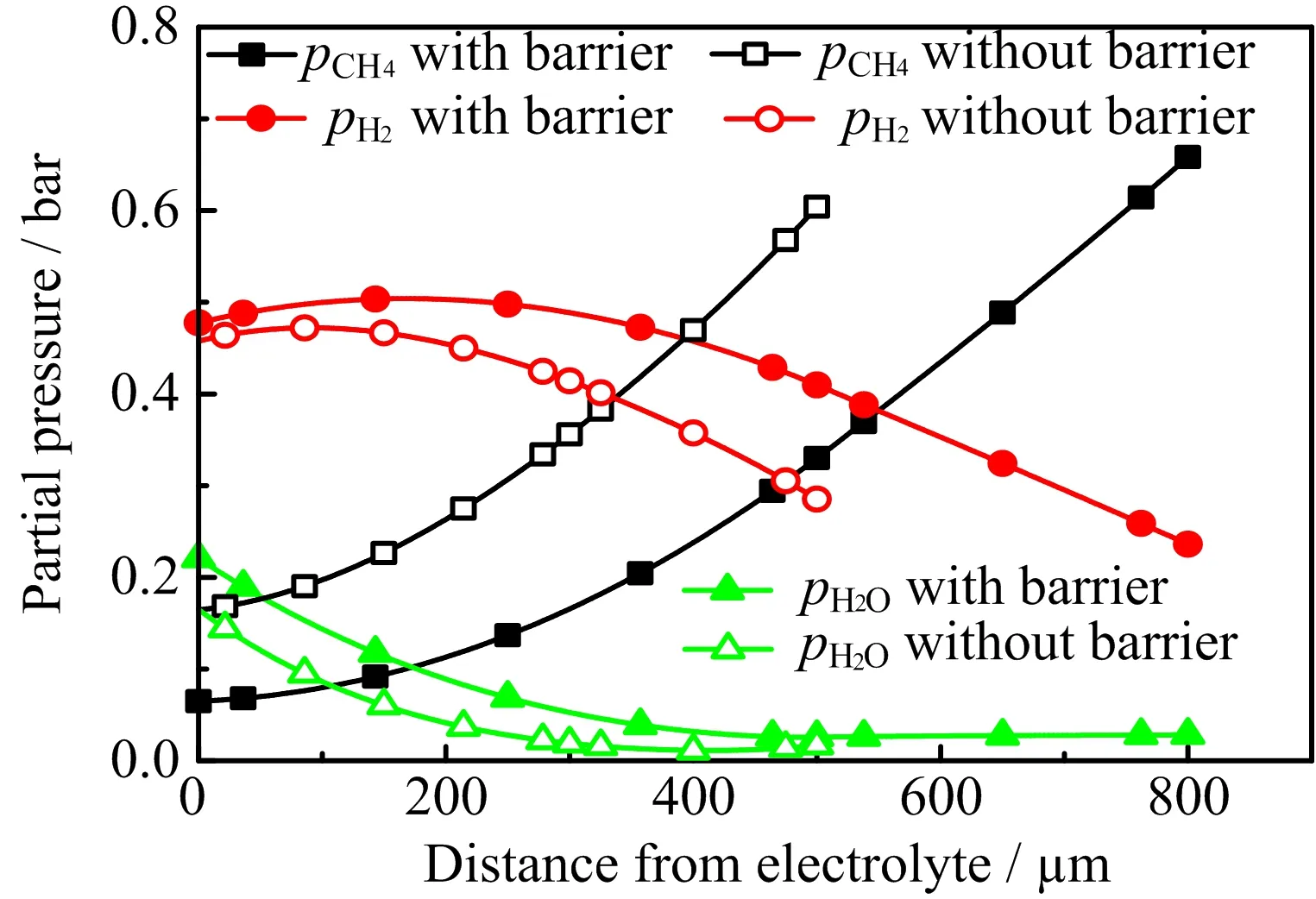
FIG.2 Partial pressures of fuel species(CH4,H2and H2O)in the anode near the fuel inlet and along the anode thickness direction for two cells,one with and another without a diffusion barrier layer. The SOFCs are operated at Vop=0.8 V,Top=1073 K and a methane flow rate of 1.084×10⁻³mol·m−1s−1.The thickness of the Ni-YSZ anode is 500µm and the thickness of the barrier layer is 300µm.
As shown in FIG.3,the maximum carbon activity of less than 1 is possible for the anode without a barrier layer when the fuel flow rate is lower than 5.242×10⁻⁴mol·m−1s−1,corresponding to a current density of 3870 A/m2and a fuel utilization of 95.7%.In comparison,the corresponding results for the anode with a barrier layer of 300µm are a fuel flow rate of 1.073×10⁻³mol·m−1s−1,a current density of 6823 A/m2and a fuel utilization of 82.4%.No matter there is a diffusion barrier layer or not,the maximum carbon activity should be below 1 in order to avoid carbon deposition.The results show that the fuel utilization ratio should stay above some minimum in order to prevent the soot formation.Moreover,the results demonstrate that the minimum fuel utilization ratio required for coking free operation is reduced by the presence of a diffusion barrier layer,consistent with the experimental observation.
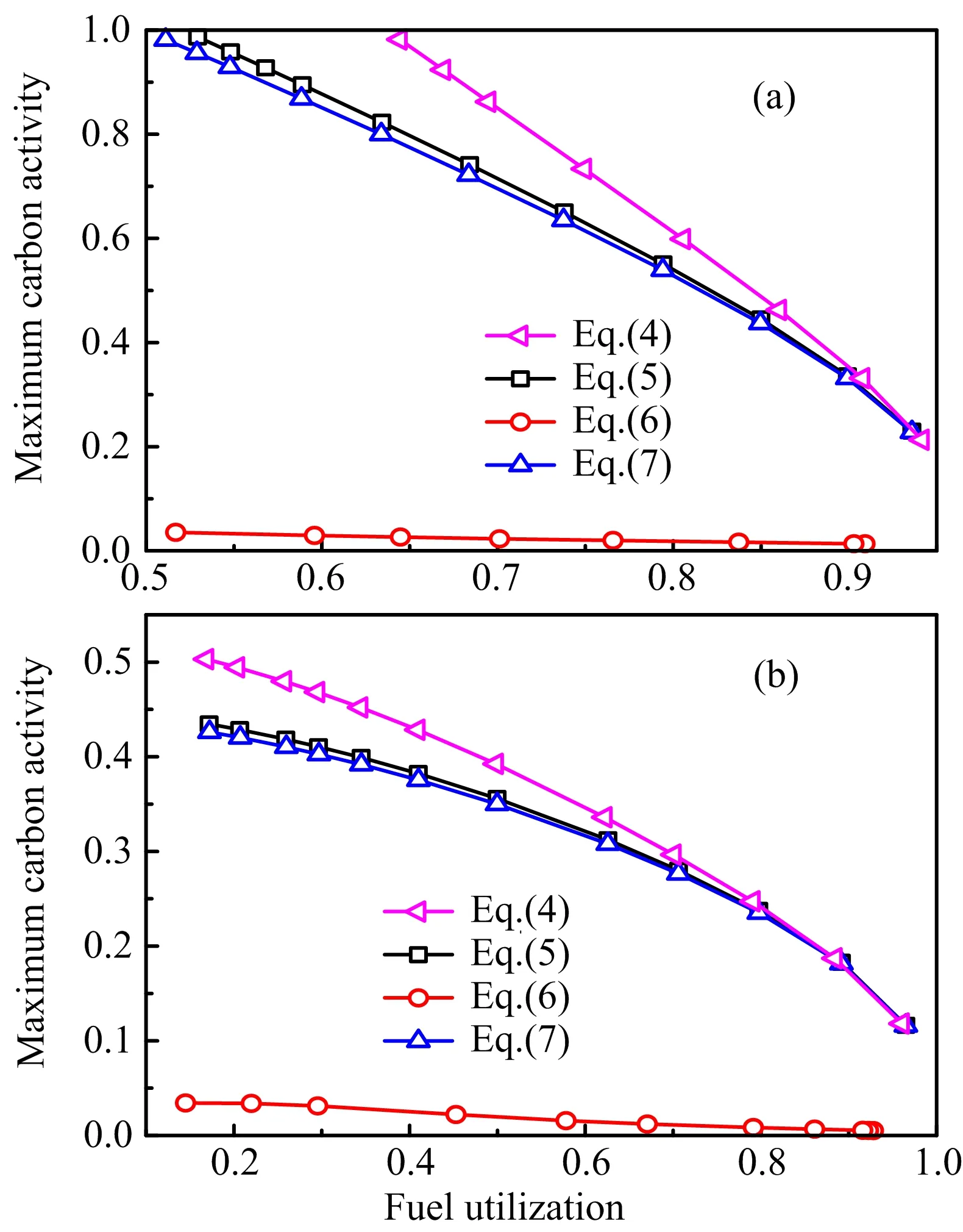
The above results also mean that,for a givenVop,the fuel flow rate should be kept below a certain threshold so that the fuel utilization ratio can be higher than the minimum value required.For a given fuel flow rate that meets the requirement withVop,it also meets the requirement withV FIG.3 Relationships among the fuel flow rate,maximum carbon activity in the Ni-YSZ anode and the fuel utilization ratio for SOFCs with and without a diffusion barrier layer(the thickness of the barrier layer is 300µm.) is chosen,increasing the current production is limited by the electrochemical performance of the cell and requires an increased input fuel flow rate.The increased fuel input results in a decrease in the fuel utilization ratio.As a result,the soot formation may occur.That is,the statement that increasing the operating current is helpful for the non-coking operation can be misleading in practice.It is valid only when it is the result of reducing the cell voltage for a given fuel flow rate.It is incorrect if the increased current output is the result of increasing the fuel supply for a given cell voltage.Therefore,the minimum fuel utilization criterion will be used below for discussing the diffusion barrier layer designs as the criterion is valid regardless of the criterion is met by reducing the fuel flow rate or by reducing the cell voltage. As mentioned above,the minimum fuel utilization for non-coking operations is over 95%for the cell without a barrier layer.Such a high fuel utilization is unrealistic in practice.The critical fuel utilization can be reduced by applying an anode diffusion barrier layer.Naturally,the effect of the barrier layer on reducing the carbon activity is dependent on the barrier layer thickness.The relationship between the fuel utilization and the maximum carbon activity in the anode as affected by the barrier layer of different thickness is shown in FIG.4. FIG.4 Relationship between the fuel utilization and maximum carbon activity in the anode with a diffusion barrier layer(the thicknesses of the barrier layer are indicated in the figure):(a)Vop=0.8 V,(b)Vop=0.7 V. As shown in FIG.4,the minimum fuel utilization ratio to keep the carbon activity in the Ni-YSZ anode to be below 1 decreases with the increase of the thickness of the barrier layer.For the case ofVop=0.8 V(FIG.4(a)),the minimum fuel utilization ratios for the barrier layers of 200,300,400,and 500µm thickness are 92%,82%,64%,and 37%,respectively.Considering that SOFCs are typically operated at a fuel utilization ratio of 70%−80%,a barrier layer thickness below 300µm is not suitable for practical use.For the fuel utilization ratio of 70%−80%,the operating current densities in unit of A/cm2for the barrier layer thicknesses of 0,400,and 500µm are in the range of(0.77,0.87),(0.66,0.74)and(0.62,0.70),respectively.The current output for a 400µm-thick barrier layer is higher and more desirable than that for a 500µm-thick barrier layer.Besides,compared to the cell with no barrier layer,the power loss caused by a 400µm-thick barrier layer is about 15%,which is moderate considering the huge bene fit of no-coking operations with no external reformer.Therefore,a barrier layer with a thickness of about 400µm is optimal for achieving high power output under non-coking condition.When a low power load is desired in practice,the non-coking condition can be easily maintained by reducing the fuel supply at the same cell voltage so that the fuel utilization increases and the carbon activity decreases. It is noted that the minimum fuel utilization ratio for non-coking condition can be substantially reduced for reducedVop,due to the accompanying increased current production.For example,as shown in FIG.4(b)forVop=0.7 V,basically all fuel utilization ratios for a barrier layer with a thickness of over 300µm meet the noncoking requirement,though the minimum fuel utilization ratio for a 200µm-thick barrier layer remains impractically high.Considering that the electrical power efficiency of SOFC is proportional toVopandVop≤0.8 V is usually required to obtain an acceptably high power density,a thickness of about 400µm is clearly more desirable than a thickness of about 300µm.Nevertheless,it is noted that a barrier layer of a thickness of about 300µm is also acceptable for the operating condition ofVop≤0.75 V. FIG.5 Effect of rMSRexpressions on the relationship between the fuel utilization and maximum carbon activity in the anode when the thickness of the barrier layer is 400µm:(a)Vop=0.8 V,(b)Vop=0.7 V. Notice that the above carbon activity results are obtained based on Eq.(4)for the MSR reaction rate.As there are a number of different experimentally determinedrMSR,to ensure the credibility of the barrier layer design result,the effect of differentrMSRexpressions on the design result is also examined.Representative testing results are shown in FIG.5.As shown in FIG.5,the carbon activity obtained with Eq.(4)is the highest for all fuel utilizations and cell voltages examined.Therefore,the above result of the barrier layer design is safe and reliable.It may be argued that the optimal barrier layer thickness may be different from the above result if a differentrMSRexpression is used.However,it is noted that Eq.(4)is the result based on the newest experimental data and is more reliable than the previous ones.Moreover,carbon deposition is fatal for the operations of SOFCs,it is highly desirable to use a safe criterion.Therefore,the above design result is strongly recommended. A multi-physics model with consideration of detailed balance of electrochemical potentials is employed to simulate the operations of SOFCs fueled by low steam methane.The effect of current generation on suppressing the soot formation is proven to be the result of the current accompanying fuel consumption and steam production that reduce the carbon activity.The minimum fuel utilization is therefore identified as a more robust indicator for the non-coking condition than that of the critical current density.The effects of fuel utilization,barrier layer thickness and operating voltage on the anode carbon activity are examined systematically.Considering the practical fuel utilization of≥70%and cell voltage of∼0.8 V required by high efficiency SOFC operations,an anode diffusion barrier layer of 400µm is found to be optimal for achieving high electrochemical performance under non-coking condition.The finding on the anode structure design opens the door for realizing the technology of low steam methane fueled SOFCs that is highly desirable based on the energy efficiency and economic considerations.Experimentalists are therefore urged to conduct validating experiments so that the technology may become a reality. This work was supported by the National Natural Science Foundation of China(No.11574284 abd No.11774324),the National Basic Research Program of China(No.2012CB215405),and Collaborative Innovation Center of Suzhou Nano Science and Technology. [1]B.C.H.Steele,Nature 400,619(1999). [2]D.Yan,C.Zhang,L.J.Liang,K.Li,L.C.Jia,J.Pu,L.Jian,X.Li,and T.Zhang,Appl.Energy 175,414(2016). [3]J.Laurencin,G.Delette,F.Usseglio-Viretta,and S.Di Iorio,J.Eur.Ceramic Soc.31,1741(2011). [4]Y.Chen,Y.X.Zhang,Y.Lin,Z.B.Yang,D.Su,M.F.Han,and F.L.Chen,Nano Energy 10,1(2014). [5]A.Ploner,A.Hagen,and A.Hauch,Fuel Cells 17,498(2017). [6]S.Sengodan,S.Choi,A.Jun,T.H.Shin,Y.W.Ju,H.Y.Jeong,J.Shin,J.T.Irvine,and G.Kim,Nat.Mater.14,205(2015). [7]M.Torrell,A.Morata,P.Kayser,M.Kendall,K.Kendall,and A.Tarancón,J.Power Sources 285,439(2015). [8]N.P.Brandon,P.Boldrin,and E.Ruiz-Trejo,Solid Oxide Fuel Cell Lifetime and Reliability,London,UK:Academic Press,79(2017). [9]T.Luo,X.J.Liu,X.Meng,H.Wu,S.R.Wang,and Z.L.Zhan,J.Power Sources 299,472(2015). [10]H.P.Ding,Z.T.Tao,S.Liu,and Y.T.Yang,J.Power Sources 327,573(2016). [11]H.Yokokawa,H.Kishimoto,T.Shimonosono,K.Yamaji,M.Muramatsu,K.Terada,K.Yashiro,and T.Kawada,J.Electrochem.Energy Conv.Stor.14,011004(2017). [12]V.Zaccaria,D.Tucker,and A.Traverso,J.Power Sources 311,175(2016). [13]J.F.Qu,W.Wang,Y.B.Chen,X.Deng,and Z.P.Shao,Appl.Energy 164,563(2016). [14]M.F.Liu,Y.Choi,L.Yang,K.Blinn,W.T.Qin,P.Liu,and M.L.Liu,Nano Energy 1,448(2012). [15]K.Park,S.Yu,J.Bae,H.Kim,and Y.Ko,Int.J.Hydrogen Energy 35,8670(2010). [16]Y.B.Lin,Z.L.Zhan,J.Liu,and S.A.Barnett,Solid State Ionics 176,1827(2005). [17]M.F.Rabuni,T.Li,P.Punmeechao,and K.Li,J.Power Sources 384,287(2018). [18]G.L.Xiao and F.L.Chen,Electrochem.Commun.13,57(2011). [19]J.Xiao,Y.M.Xie,J.Liu,and M.L.Liu,J.Power Sources 268,508(2014). [20]D.Lee,J.Myung,J.Tan,S.H.Hyun,J.T.S.Irvine,J.Kim,and J.Moon,J.Power Sources 345,30(2017). [21]A.Ideris,E.Croiset,M.Pritzker,and A.Amin,Int.J.Hydrogen Energy 42,23118(2017). [22]B.X.Wang,J.Zhu,and Z.J.Lin,Chin.J.Chem.Phys.28,299(2015). [23]D.Mogensen,J.D.Grunwaldt,P.V.Hendriksen,K.Dam-Johansen,and J.U.Nielsen,J.Power Sources 196,25(2011). [24]Y.B.Lin,Z.J.Zhan,and S.A.Barnett,J.Power Sources 158,1313(2006). [25]W.Kong,H.Y.Zhu,Z.Y.Fei,and Z.J.Lin,J.Power Sources 206,171(2012). [26]B.X.Wang,J.Zhu,and Z.J.Lin,Appl.Energy 176,1(2016). [27]J.Liu and S.A.Barnett,J.Am.Ceram.Soc.85,3096(2002). [28]J.Liu and S.A.Barnett,Solid State Ionics 158,11(2003). [29]COMSOL-Multiphysics,COMSOL Multiphysics User’s Guide Version 3.5,Stokholm,Sweden:COMSOL AB,(2008). [30]J.M.Klein,Y.Bultel,S.Georges,and M.Pons,Chem.Eng.Sci.62,1636(2007). [31]I.Alstrup,M.T.Tavares,C.A.Bernardo,O.Sørensen,and J.Rostrup-Nielsen,Mater.Corros.49,367(1998). [32]J.M.Wei and E.Iglesia,J.Catal.224,370(2004). [33]S.Safvi,E.Bianchini,and C.R.F.Lund,Carbon 29,1245(1991). [34]W.Sangtongkitcharoen, S.Assabumrungrat, V.Pavarajarn,N.Laosiripojana,and P.Praserthdam,J.Power Sources 142,75(2005). [35]M.Zeppieri,P.L.Villa,N.Verdone,M.Scarsella,and P.De Filippis,Appl.Catal.A 387,147(2010). [36]F.P.Nagel,T.J.Schildhauer,S.M.A.Biollaz,and S.Stucki,J.Power Sources 184,129(2008). [37]M.Andersson,H.Paradis,J.L.Yuan,and B.Sund´en,Int.J.Energy Res.35,1340(2011). [38]I.Drescher,W.Lehnert,and J.Meusinger,Electrochim.Acta 43,3059(1998). [39]R.Leinfelder,Ph.D.Thesis,Universit¨at Erlangen-N¨urnberg,(2004). [40]E.Achenbach and E.Riensche,J.Power Sources 52,283(1994).
C.Barrier layer thickness and minimum fuel utilization for non-coking operations

IV.CONCLUSION
V.ACKNOWLEDGEMENTS
 CHINESE JOURNAL OF CHEMICAL PHYSICS2018年5期
- CHINESE JOURNAL OF CHEMICAL PHYSICS的其它文章
- A Simple,Compact and Rigid Scanning Tunneling Microscope
- Extraction of Lignin from Tobacco Stem using Ionic Liquid
- Gd Doped Hollow Nanoscale Coordination Polymers as Multimodal Imaging Agents and a Potential Drug Delivery Carriers
- 3D Macro-Micro-Mesoporous FeC2O4/Graphene Hydrogel Electrode for High-Performance 2.5 V Aqueous Asymmetric Supercapacitors
- Gamma Ray Radiation Effect on Bi2WO6Photocatalyst
- Ag-Cu Nanoparticles Supported on N-Doped TiO2Nanowire Arrays for Efficient Photocatalytic CO2Reduction