Influence of cement- fly ash-gravel pile-supported approach embankment on abutment piles in soft ground
D.Xio,G.L.Jing,D.Lio,Y.F.Hu,X.F.Liu
aSchool of Civil Engineering,Southwest Jiaotong University,Chengdu,610031,China
bHighway Planning,Survey,Design,and Research Institute,Sichuan Provincial Transport Department,Chengdu,610041,China
Keywords:Abutment pile Soft soil Soil movement Ground improvement Load transfer
A B S T R A C T Abutment piles in soft ground may be subjected to both vertical and horizontal soil movements resulting from approach embankment loads.To constrain the soil movements,the soft soil ground beneath the approach embankment is often improved using composite pile foundations,which aim at mitigating the bump induced by high-speed trains passing through the bridge.So far,there is limited literature on exploring the influence of the degree of ground improvement on abutment piles installed in soft soil grounds.In this paper,a series of three-dimensional(3D)centrifuge model tests was performed on an approach embankment over a silty clay deposit improved by cement- fly ash-gravel(CFG)piles combined with geogrid.Emphasis is placed on the effects of ground replacement ratio(m)on the responses of the abutment piles induced by embankment loads.Meanwhile,a numerical study was conducted with varying ground replacement ratio of the pile-reinforced grounds.Results show that the performance of the abutment piles is significantly improved when reinforcing the ground with CFG piles beneath the approach embankment.Interestingly,there is a threshold value of the replacement ratio of around 4.9%above which the effect of CFG pile foundations is limited.This implies that it is essential to optimize the ground improvement for having a cost-effective design while minimizing the risk of the bump at the end of bridge.
1.Introduction
In railway engineering,it has been well recognized that the engineering problems associated with the so-called“bump at the end of bridge”in the bridge approach embankment(BAE)are challenging to the long-term operating safety and comfort of railways.The bump is mainly caused by abrupt changes in track stiffness,which are associated with structural and foundation discontinuities,differential settlement of the back fill,etc.On the other hand,construction of the approach embankment over soft grounds may result in significant vertical and horizontal soil movements.The soil movements may in turn induce additional stresses and displacements in neighboring abutment piles.In consequence,an intolerable movement or even structural failure of the piles or bridge structure may take place(Tavenas et al.,1979).Therefore,it is of great interest for researchers to study the behavior of abutment piles subjected to soil movements resulting from approach embankments.For instance,a series of reduced scale model tests was conducted by Chen et al.(1997)and Pan et al.(2000)to examine the response of single pile or pile groups subjected to lateral soil movements.Ellis and Springman(2001)later carried out two-dimensional(2D)plane-strain analysis using finite element method(FEM)to investigate the pile-soil interaction of a pile-supported bridge abutment over soft grounds.Similar studies were also conducted by Brans by and Springman(1997)and Stewart et al.(1994)using three-dimensional(3D)FEM analyses combined with centrifuge model tests and field tests in order to derive recommendations for the design of abutment piles subjected to lateral soil movements.Additionally,Jeong et al.(2004)studied the time dependent behavior of pile-reinforced soft clay grounds induced by staged construction of embankment.
The studies mentioned above only focus on approach embankments resting on natural soft soil grounds without improvement.This is because these studies are contextualized in engineering background of highway embankments which require less strict control of differential settlement.On the contrary,the approach embankment of high-speed railways requires a much more strict settlement control.Thus,pile foundations are often adopted beneath the approach embankment in order to minimize the influence of soil movements on abutment piles.So far,a few researchers have examined the effects of the soft soil ground improvement under embankment loads on the behavior of abutment piles.A numerical study performed by Zheng et al.(2013)showed that mechanical properties of soft soil beneath approach embankments have a considerable impact on the response of abutment piles.Jiang et al.(2012)and Wang(2012)investigated the effects of ground improvements beneath an approach embankment on the differential settlements between the bridge abutment and its approach embankment in different construction scenarios.However,the influence of pile-supported approach embankments on the behavior of abutment piles has not been addressed.
This paper describes the results of a series of centrifuge model tests and 3D numerical simulations,in order to understand the behavior of abutment piles while varying the replacement ratio(m)of composite pile foundations beneath an approach embankment.Emphasis is put on the analyses of axial force,bending moment,contact pressure and horizontal displacement developed in the abutment piles.Recommendations are provided for optimizing the ground improvement design for the bridge approach embankment in order to ensure the long-term stability of the high-speed railway track.
2.Centrifuge modeling
2.1.Experimental setup
In this study,four centrifuge model tests were conducted at the Geotechnical Centrifuge Facility of Southwest Jiaotong University,using a 100g t centrifuge system with a maximum acceleration of 200g and an effective radius of 2.7 m.Details on the centrifuge can be found in Xiao et al.(2017).The model container used for the centrifuge model tests is made of aluminum alloy and has dimensions of 800 mm×600 mm×600 mm(length×width×height).The scaling laws reported by Ng and Lu(2014)were applied for the centrifuge model tests.All the centrifuge model tests were performed at a nominal radial acceleration of 80g,thus the same vertical effective stress profile will be produced during the centrifuge model tests as that for a prototype 80 times larger in dimensions.The schematic layout of the centrifuge model test is presented in Fig.1.
The model ground consists of a soft silty clay layer of 100 mm in thickness,which is underlaid by a layer of 250 mm-thick over consolidated clay.The abutment piles contain three rows of piles having a length of 195 mm and an external diameter of 12 mm.The center-to-center pile spacing is 37.5 mm along the pile row and 40 mm between pile rows(see Fig.2).The concrete pile cap is 32 mm thick,connected with the retaining wall as a whole by castin-place,which was designed to be rigid in bending compared to the piles.The model embankment has front and side slopes at a ratio of approximately 1.5:1.Four replacement ratios(m=2.2%,3.1%,4.9%and 8.7%)of composite pile foundation are considered.Table 1 summarizes the pile parameters utilized in the 4 centrifuge model tests,including the concrete- fly ash-gravel(CFG)and abutment piles.Note that the corresponding values at the prototype scale are listed in square brackets.
2.2.Soil properties and sample preparation
The soil used for the centrifuge model tests was sampled from a field testing site in Chengdu.It is called “Chengdu clay”and is a typical soft clay in Chengdu Plain.The upper silty clay layer was prepared from the slurry of Chengdu silty clay,while the lower clay was prepared from the slurry of Chengdu clay.For the model tests with similar properties of both silty clay and clay in site,the density and water content were regarded as the major controlling parameters,followed by the strength index.The soil samples obtained from the field were air-dried and crushed mechanically and then passed through the 2 mm sieve.Afterwards,the air-dried soil powder was mixed with water to reach required water content using deaired water and then mixed mechanically.The clay slurry was deaired for at least 24 h under vacuum condition.Owing to the given soil unit weight,the weight of test soil per height of soil layer in container needed in the tests can be determined beforehand.Then the clay slurry was placed horizontally in layers bottom-up to the height of 25 cm by 2 cm thickness of each filling layer in the strongbox.The silty clay was placed by the same way up to the height of 35 cm.Consolidation and quick direct shear tests for the remolded soil samples were carried out to determine the physical and mechanical properties.The properties of the soil are listed in Table 2 and are used in all the tests.All the inner sides of the model box were lubricated by silicon grease to minimize wall friction,prior to pouring the clay slurry into the container.
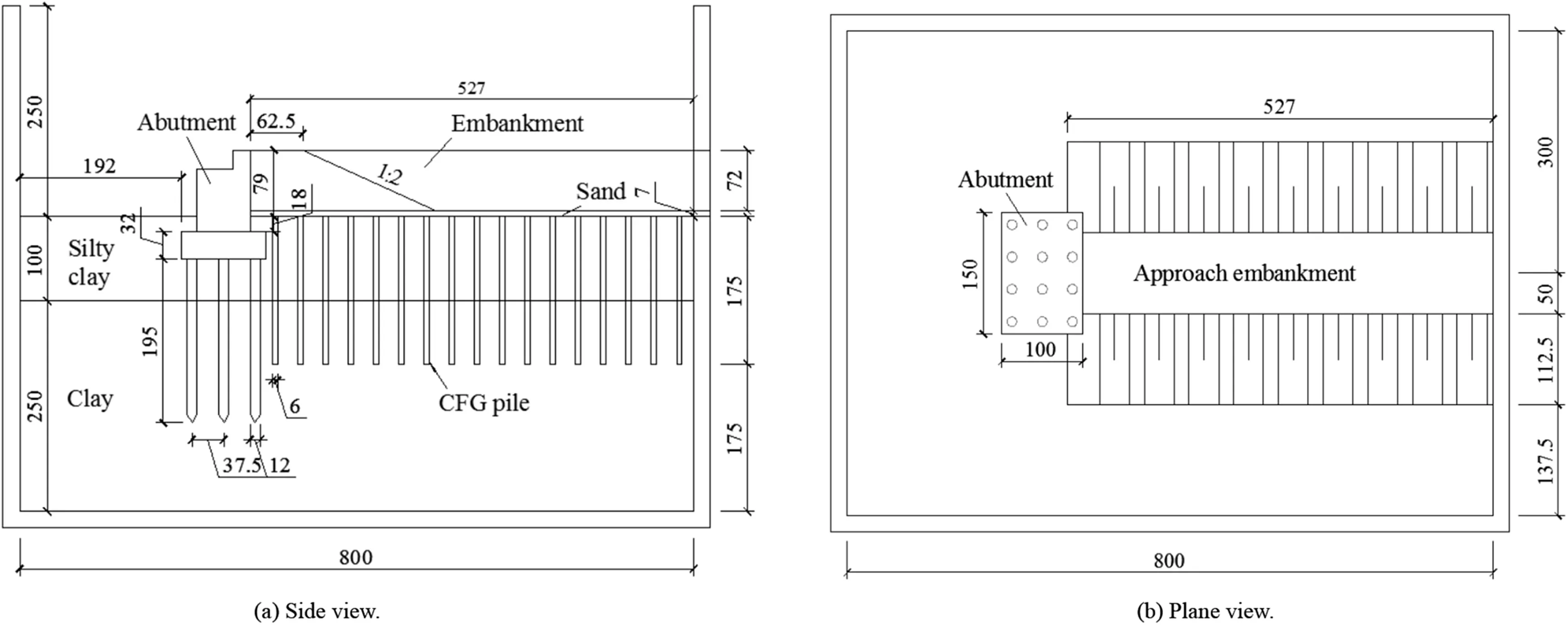
Fig.1.Schematic layout of bridge approach in the centrifuge model tests(unit:mm).
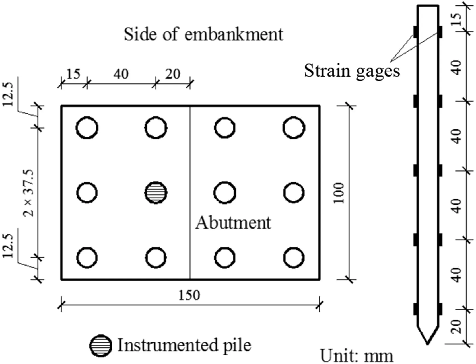
Fig.2.Plane view of abutment piles in centrifuge model tests(left)and side view of an instrumented pile(right).
2.3.Model piles and instrumentation
Model abutment piles are made of aluminum alloy with a hollow circular section having 12 mm in outer diameter and 1 mm in wall thickness.According to the scaling laws proposed by Ng and Lu(2014),the model piles are equivalent to the reinforced concrete piles of 15.6 m in length and 960 mm in outer diameter in prototype.The model piles have a Young’s modulus(Ep)of 70 GPa,an axial stiffness(EmAm)of 2419 kN and a bending stiffness(EmIm)of 36 N m2.The corresponding EpApand EpIpvalues at the prototype scale are 15,482 kN and 1474 N m2,respectively.Six miniature strain gages were bonded in pairs along the length of the instrumented pile(Fig.2)to measure the axial force and bending moment using a fully active bridge circuit.To reduce potential mechanical damage,the strain gages were coated by a thin layer of epoxy and sealed with a thin waterproof membrane.The strain gages are 2 mm long,with resistance of 350Ω.They are placed at a spacing of 40 mm,as shown in Fig.2.The position of the instrumented piles can be seen in Fig.2.
Additionally,the CFG model piles beneath the approach embankment are made of aluminum tube,and are6 mm in external diameter,175 mm in length,and 1 mm in wall thickness.It is almost impossible to manufacture the model piles using the raw material of CFG piles in such a small size(the diameter is 6 mm).The common practice is to adopt the aluminum material to substitute the CFG material.However,the modulus of the aluminum is much larger than that of the CFG pile.According to the equivalent principle of stiffness,it is feasible to use the aluminum tube(wall thickness is 1 mm),i.e.to reduce the cross-sectional area of aluminum pile,and model the CFG piles with the same outer diameter.More test details are presented by Hang(2011).
2.4.Testing procedure
On completion of soil preparation,the model container was mounted onto the platform of the centrifuge.An initial consolidation stage was set for 2 h at an acceleration of 80 g to allow for the dissipation of excess pore water pressure in the clay layer and thus to maintain the soil settlement.Then,the centrifuge was paused for the installation of the piled abutment at the designed location,as presented in Fig.3.In order to avoid squeezing effect,a drilling rig with boring crown having the same diameter with the piles was firstly used to drill hole at the designed pile locations until the designed depth.Then a hydraulic jack was utilized to vertically install the premanufactured piled abutment slowly till the desirable depth.This implies that the abutment piles modeled in this centrifuge model test,regarded as “wished-in-place”,were intended to simulate bored piles.Afterwards,the CFG model piles were installed in the clay ground at a given replacement ratio(Table 1),on which a prefabricated clayey embankment model was placed.Finally,the centrifuge was run at an acceleration of 80g and the responses of the instrumented abutment piles were monitored.
3.Numerical analysis
A finite difference code FLAC3D developed by Itasca(2005)was employed for numerically analyzing the effects of CFG pile-supported approach embankment on the behavior of abutment piles.The 3D numerical model was validated against the results obtained from the centrifuge model tests,and parametric study was further performed to reveal the key factors affecting the response of abutment piles,with a specific emphasis on the influence of ground replacement ratio of pile foundations.
Numerical study was carried out based on the centrifuge model tests.It should be noted that:(1)the geometry of the numerical model is identical to that of the prototype corresponding to 3D centrifugal model;(2)the controlling in dices in the physical and mechanical properties of the ground and the structure for numerical simulation need to be kept consistent with the centrifuge tests,such as unit weight,water content,and elastic modulus;(3)the mechanical and seepage boundary conditions of the numerical model are identical to the ones of centrifuge tests;and(4)the construction sequence of the established numerical model is in agreement with that of the centrifuge model tests.

Table 1Pile properties used in centrifuge model tests.

Table 2Parameters of soils used for the centrifuge model tests.
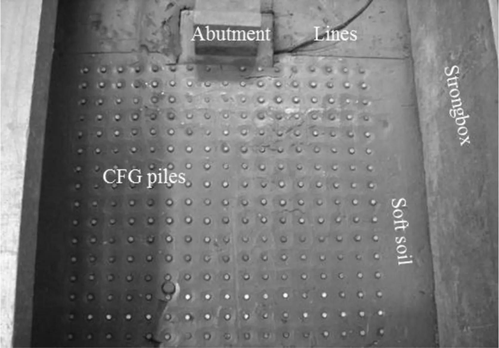
Fig.3.A typical completed pile foundation nearby a piled abutment.
3.1.Numerical model and boundary conditions
Based on the geometry of prototype of centrifuge model,a fullscale 3D numerical model was established,as presented in Fig.4,where x,y and z refer to the transverse,longitudinal and vertical directions,respectively.In the numerical model,a contact element used at the interfaces between the piles and the surrounding soil can realize pile-soil contact,slippage and disjointing.
The boundary conditions adopted for the model are shown in Fig.5.The displacements along the x-direction on all side boundaries are not permitted while those along the x-and y-directions at the bottom of the model are not allowed.Following the validation of the numerical model against the results from the centrifuge model tests,four values of replacement ratio(m)of 8.7%,4.9%,3.1%and 2.2%are considered for the parametric study to simulate different degrees of ground improvement,corresponding to the CFG pile spacing-diameter ratios of 3,4,5 and 6,respectively.The abutment piles are modeled as pile elements with a thickness of 2 mm.
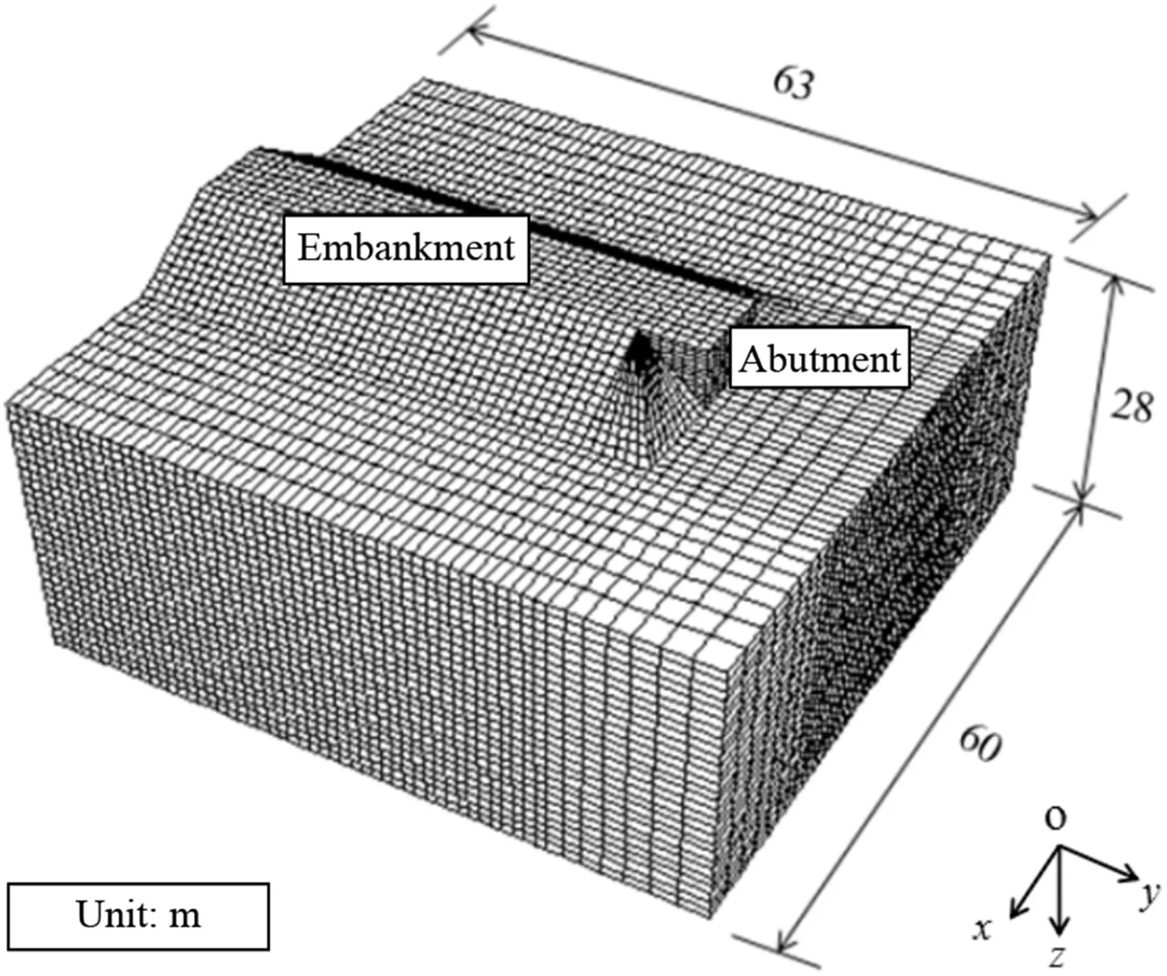
Fig.4.Overview of 3D numerical model of a bridge approach.
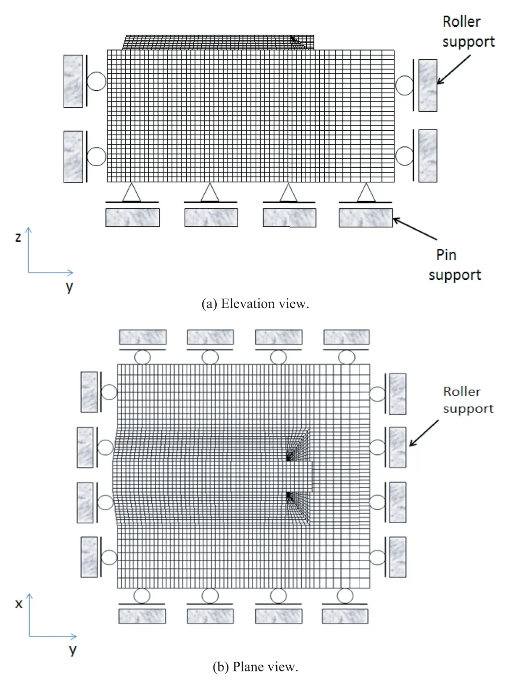
Fig.5.Boundary conditions used in the numerical analysis.
3.2.Constitutive model and parameters
In the numerical model,an elasto-perfectly plastic model using the Mohr-Coulomb(MC)failure criterion was adopted for the clays.The same model was also applied to the embankment fill material.All the MC material parameters are summarized in Table 3.Note that the geogrid layer between the pile foundation and the approach embankment is not considered since the model embankment is rigid.
Table 4 summarizes all the parameters of the piles and the contact elements used for interfaces.The model piles are modeled as a linear-elastic material.Interfaces 1 and 2 represent the contact elements between the piles and the upper silty clay layer and the lower clay layer,respectively.
3.3.Numerical procedures
Each numerical analysis follows the same procedures as those for the centrifuge model test:
(1)Establish the mesh of the ground model on the basis of prototype scale,assign the constitutive model and material properties to the soil layers,set up the initial boundary conditions,and then create the initial stress state in the two layer ground under dead weight.

Table 3Constitutive parameters of geo-material.

Table 4Material properties of elastic piles and the interface elements.
(2)Set the initial boundary conditions and then create initial stress state in the two-layer soil profile under deadweight.
(3)Place the piled abutment model at the designed position while implementing the contact elements to model the interactions between the structures and the soil,and then complete the consolidation stage in the ground due to the deadweight of the abutment.
(4)Reinforce the soft ground beneath the embankment using CFG piles modeled as the pile elements with different replacement ratios,and then apply the embankment load in 3 parts,i.e.2 m(40 kPa),4 m(80 kPa),and 6 m(120 kPa)of embankment height in order to model the staged construction.Induced axial force,bending moment and contact pressure along the instrumented abutment piles are monitored at each construction stage.
4.Results
It should be noted that all the test measurements presented in this paper are converted to prototype values unless stated specifically.
4.1.Induced axial force of abutment piles
Fig.6 compares the measured and computed distributions of axial force along the abutment pile at different replacement ratios of pile foundation.It can be seen that the distribution of the obtained pile axial force(p)exhibits a similar shape.An initial increase in p is followed by a decrease,as observed by Cai and Liu(2004).This behavior implies that the abutment piles are subjected to negative skin frictional forces induced by the settlements of surrounding soil under embankment loads.With the staged construction of embankment,the upper layer of the soft ground experiences much more significant settlements than the abutment piles at the same depth,leading to significant differential settlements and thus the generation of pile negative friction.Herein,it is worth noting that the axial force described above is completely caused by the pile negative skin frictions without considering the effect of the deadweight of pile caps.In other words,the more the negative friction generated,the more the induced axial force.In addition,trends of all the computed axial forces along the abutment pile are broadly consistent with the measured ones at different replacement ratios,despite of some minor differences.Therefore,the validity of the numerical analyses is verified.That is,despite of the use of simple constitutive models for soils and pile materials,the 3D numerical model established can be further used for a parametric study to investigate the effects of the degree of ground improvement on the behavior of abutment piles.
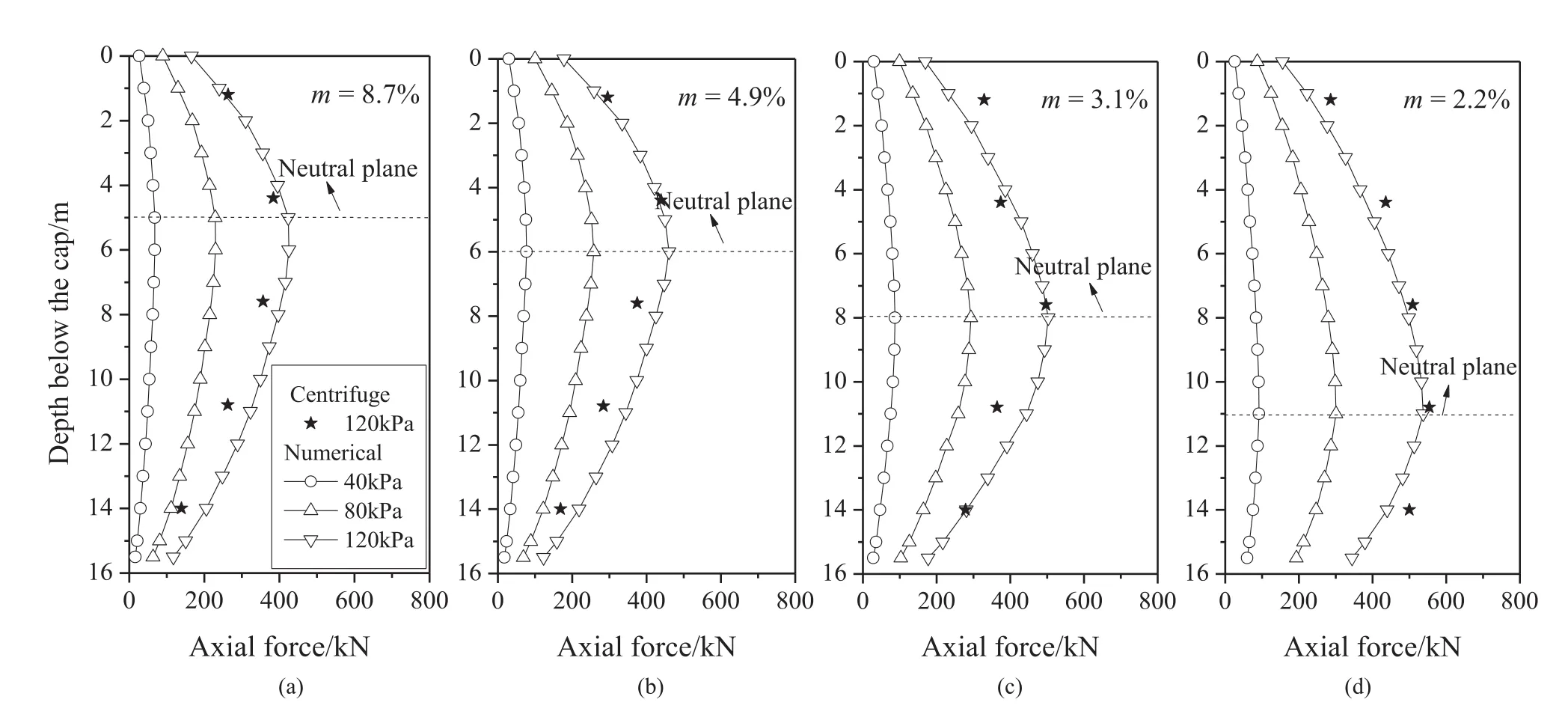
Fig.6.Comparison of measured and computed axial force distributions along the abutment piles for different replacement ratios.
To further reveal the effect of ground replacement ratios,Fig.7 plots the evolution of the maximum axial force(pmax)induced and the depth of neutral points(kink points of axial force profiles)of abutment piles with respect to the ground replacement ratio.It is observed that with the increase in m,pmaxdecreases whereas the corresponding neutral point shifts upwards.This can be explained by the fact that higher value of m means more proportion of embankment loads transferred through CFG piles to deeper soil strata,leading to less settlement in the upper soil layers and thus lower negative skin frictional forces induced.Consequently,the neutral points tend to move upwards.Furthermore,for the values of m above 4.9%,the changes in pmaxand the depth of neutral point are limited.
4.2.Normal contact pressure
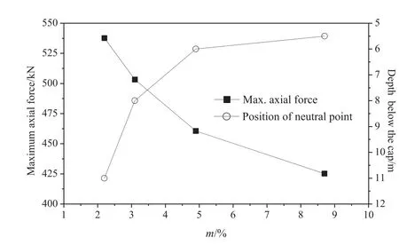
Fig.7.Evolutions of the maximum axial force and position of neutral point with the ground replacement ratio.
Fig.8 presents the normal contact pressure profiles along the abutment piles for different ground replacement ratios.Note that the contact pressure in the direction towards the bridge(i.e.away from the embankment)is considered positive,otherwise it is negative.It can be observed that the profiles of normal pressure along the pile shaft exhibit a sudden discontinuous change at the interface between the soft soil and relatively stiffer soil layer.This is mainly attributed to significant lateral soil flow occurring at the interface of soil layers.In addition,the abutment piles at depths below 4 m are subjected tonegative normal forces in the upper part while positive forces in the lower part.With the increasing ground replacement ratio m,the neutral point(zeronormal pressure)tends to move upwards.This highlights the load transfer mechanism of pile foundations,implying that the higher the value of m,the larger the positive normal pressure applied to the abutment piles.
Fig.9 shows the rose diagrams of the normal contact pressures of the abutment piles at different depths of 0.1 m,3 m,9 m and 15.5 m,respectively.First observation is the symmetrical distribution of normal contact pressures along the longitudinal direction with the maximum value occurring on either the front face of piles or their back face(corresponding to an angle of 0°or 180°).The shielding effect of CFG piles reduces the lateral soil flow induced by the embankment.The normal contact pressure decreases significantly at the depth of ground reinforcement(CFG pile length)such as z=0.1 m,3 m and 9 m with increasing m values.In contrast,the opposite response appears for the normal contact pressure at z=15.5 m(approaching the abutment pile tip),which increases with the increase of m.This is due to the fact that despite of the shielding effect of CFG piles in the range of pile length,there is a significant stress concentration at the CFG pile tip,as illustrated by Zhang et al.(2015),leading to the substantial lateral soil flow towards the abutment piles and thus a significant increase in the normal contact pressures at z=15.5 m.
4.3.Bending moment of abutment piles
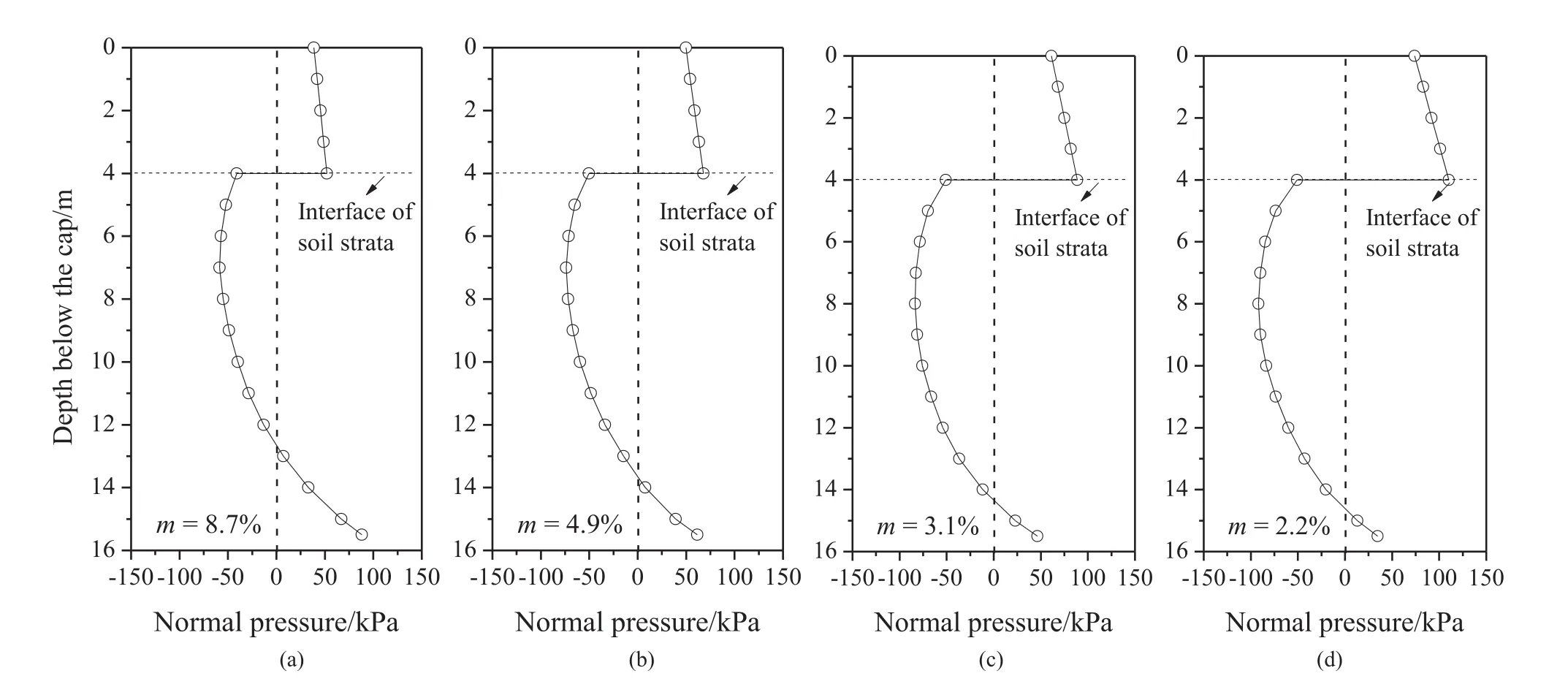
Fig.8.Profiles of normal contact pressures along the abutment piles at different replacement ratios.
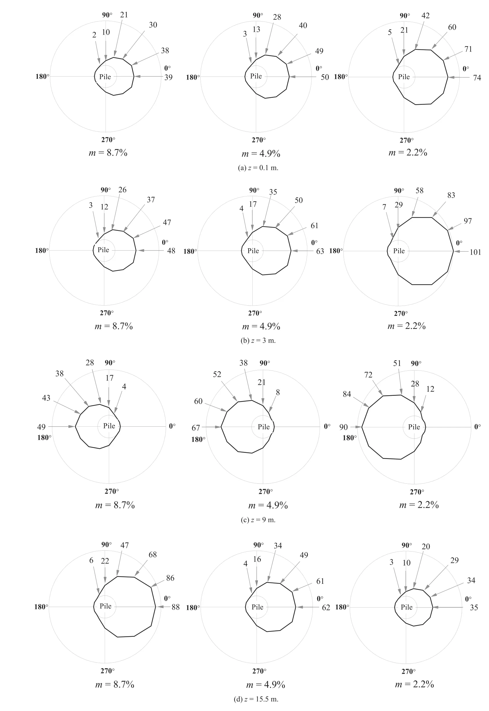
Fig.9.Normal contact pressures of the abutment piles for different depths(unit:kPa).
Fig.10 shows the profiles of embankment-induced bending moments along the abutment piles at different ground replacement ratios.Note that the bending moment of the abutment piles is regarded to be positive if the pile deflects towards the bridge structure,otherwise it is negative,when using the pile cap as a reference position.Consistent with the profiles of normal contact pressures,the shape of the pile bending moment distributions is similar at different replacement ratios with the negative moment lying at pile heads owing tothe constraint of pile caps.It can be also seen that with increasing ground replacement ratio(m),the neutral point corresponding to zero bending moment moves upwards.Correspondingly,above the neutral points,the maximum bending moments occurring at pile caps increase with the decreasing replacement ratio.On the contrary,the opposite responses can be observed for the bending moments below the neutral points.The trend of induced bending moments was captured by the numerical analyses.However,the computed bending moments almost overestimate the measured values along the depth of the abutment piles.
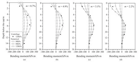
Fig.10.Comparison of measured and computed bending moments along the abutment pile at different replacement ratios.
Fig.11 shows the changes in the maximum bending moment of the abutment pile in response to embankment loads plotted against m.It can be seen that as m increases from 2%to 4.2%,the maximum bending moment occurring at the pile head decreases substantially.However,as m increases further from4.2%to 8.7%,the maximum bending moment increases slowly with its position shifting from pile tip to mid-depth of pile shaft.Interestingly,this characteristic seems to suggest that there is an optimal value of m(around 4.2%)at which the pile bending moment reaches the minimum.At this point,the moment at the pile cap level equals that at the mid-depth of pile shaft.
4.4.Horizontal displacement of abutment piles
Fig.12 presents the horizontal displacement profiles of the abutment piles for different ground replacement ratios in case of fullyconstructed embankment.The horizontal displacements along the pile shaft exhibit a nonlinear feature,indicating that the abutment pile experiences a deflection.It can be observed that the maximum horizontal displacement occurs at the pile head,with small displacement towards the embankment close to the pile tip.With the increasing replacement ratio,the horizontal displacement reduces due to the confining effect of the pile foundations.
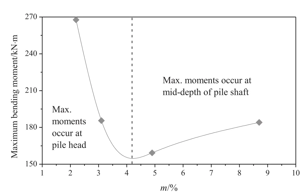
Fig.11.Relationship between the maximum bending moments and replacement ratio.
To further describe this behavior,the horizontal displacement of the pile head and the rotation angle are plotted against the ground replacement ratio(m)in Fig.13.We can see that there is a significant nonlinear decrease in both the horizontal displacement and the rotation angle with the increasing m.This behavior is consistent with the decrease in pile-soil contact pressures,as shown in Figs.8 and 9,leading to a reduction in pile lateral displacement and rotation.Such phenomena were also observed by Wang(2012)and Xiao et al.(2017).The change in lateral displacement of pile head is more pronounced against the replacement ratio m between 2.2%and 4.9%and tends to stabilize at higher values of m.This highlights that it is essential to optimize the design of ground improvement for approach embankment in order to balance its efficiency and corresponding costs in practical engineering.For instance,the replacement ratio of 4.9%would be the optimal value for the ground reinforcement beneath the approach embankment in the present case study.
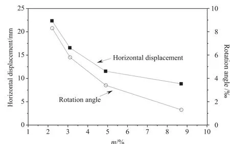
Fig.13.Relationships between the horizontal displacement and rotation angle of pile head and the replacement ratio.
5.Conclusions
A series of 3D centrifuge model tests and numerical analysis were carried out to explore the effect of soft ground reinforcement on the response of abutment piles,in terms of axial force,bending moment and lateral displacement as well as pile-soil normal contact pressure induced by embankment loads.Based on the experimental and numerical results,the main conclusions can be summarized as follows:
(1)A significant reduction in the axial force of abutment piles can be induced by enhancing the ground improvement.This is attributed to the change in negative skin forces induced by the differential settlements between the abutment piles and the piled foundation beneath the approach embankment.The maximum axial force induced decreases as m increases,accompanied by the upward shifting of the corresponding neutral point due to the load transfer capability of CFG piles to the deeper soil layers.
(2)Increasing the replacement ratio m reduces the normal contact pressures in the abutment piles.Consequently,there is a significant reduction in the corresponding bending moment and horizontal displacement of abutment piles.Comparisons of above-mentioned responses of abutment piles for different ground replacement ratios suggest that there is a critical value of ground replacement ratio(about 4.9%)above which the efficiency of pile foundations beneath the approach embankment is limited.Therefore,it is essential to optimize the design of ground improvement beneath the approach embankment in order to balance its efficiency and corresponding costs while ensuring the long-term stability of high-speed railway track.
Conflicts of interest
The authors wish to confirm that there are no known conflicts of interest associated with this publication and there has been no significant financial support for this work that could have influenced its outcome.
Acknowledgements
The work described in this paper was funded by the Science and Technology Department of Railway Ministry(Grant No.Z2012-061).The centrifuge model tests reported were carried out at the Geotechnical Centrifuge Facility of Southwest Jiaotong University.Jingmei Liao,associate director of the laboratory,is gratefully acknowledged for the technical guidance during the preliminary phase of centrifuge tests.
 Journal of Rock Mechanics and Geotechnical Engineering2018年5期
- Journal of Rock Mechanics and Geotechnical Engineering的其它文章
- Dynamic properties and liquefaction behaviour of cohesive soil in northeast India under staged cyclic loading
- Blast-induced rock damage control in Fangchenggang nuclear power station,China
- A comparative study between gravel and rubber drainage columns for mitigation of liquefaction hazards
- Bearing behavior and failure mechanism of squeezed branch piles
- Experimental evaluation of mechanically stabilized earth walls with recycled crumb rubbers
- Saturated anisotropic hydraulic conductivity of a compacted lateritic soil
