Blast-induced rock damage control in Fangchenggang nuclear power station,China
Yongqing Zeng,Haibo Li,Xiang Xia,Bo Liu,Hong Zuo,Jinlin Jiang
aState Key Laboratory of Geomechanics and Geotechnical Engineering,Institute of Rock and Soil Mechanics,Chinese Academy of Sciences,Wuhan,430071,China
bUniversity of Chinese Academy of Sciences,Beijing,100049,China
Keywords:Blast vibration signal Wave propagation regularity Acoustic test Bedrock damage Safety control
A B S T R A C T In the process of blasting excavation,stress wave propagation and gas expansion can basically induce damage to surrounding rocks,which is detrimental to rock mass integrity and engineering safety.In this case,evaluation and control of blast-induced effects are essential to the safety of nearby buildings and integrity of bedrock in blasting field.In Fangchenggang nuclear power station of China,the drill-andblast method was employed for bedrock excavation.In order to reduce the blast-induced damage zone,the wave propagation and associated damage to rock mass should be carefully investigated.In this paper,the wave propagation regressively obtained from field monitoring data was presented based on empirical formula(e.g.Sadovsky formula).The relationship between the peak particle velocity(PPV)at a distance of 30 m away from the charge hole and charge per delay in blast design was derived.Meanwhile,the acoustic tests before and after blasting were conducted to determine the damage depth of rock mass.The charge per delay in blast design was then calibrated based on the blast-induced wave propagation regularity.The results showed that a satisfactory effect was achieved on blast-induced damage control of rock mass.This could be helpful to rock damage control in similar blasting projects.
1.Introduction
Blasting is an effective method for rock mass excavation in construction of nuclear power station.In the process of blasting excavation,blast-induced damage to surrounding rocks is detrimental to the rock mass integrity and engineering safety(Henrych,1979;Gao and Yang,1999).Studies of the wave propagation characteristics and damage quantification in rock mass are of great significance for rock damage control under blasting(Morlet,1982;Li et al.,2009;Li,2014).
It is generally acceptable that stress wave induced by blasting is the major factor that causes damage to bedrock.Various researches on the damage characteristics of bedrock under blasting have been carried out using field measurement and theoretical analysis.For example,the acoustic borehole technique was widely used to study the influence of blasting excavation and showed that the blasting effect can be well controlled in the process of excavation(Zhu and Yu,2001;Zhang and Liang,2012;Yang et al.,2016).Raina et al.(2000)presented 20 methods for rock mass damage assessment and suggested that several methods should be jointly used to achieve good quantitative estimate of the damage.Zhang(2001)measured the microcracking zone boundaries of rock mass under blasting using the computer tomography(CT)and calculated the allowable vibration velocities of rock particles(ranging from 13.8 cm/s to 16.6 cm/s).Huang and Song(1999)found that the remained bedrock was slightly damaged when the peak particle velocity(PPV)of rock mass was below 3.5 cm/s.Hamdi et al.(2011)proposed an experimental method using digital image technique to assess the internal microcracks and quantify the rock damage within rock cores.Tripathy et al.(2016)proposed a systematic rock blasting approach to complete the rock excavation safely without endangering the safety of surrounding structures.Kabwe(2018)assessed the blast performance through measuring the velocity of detonation for emulsion explosives and degree of blast fragmentation conducted on an open pit blast.Besides,extensive work on this subject has been carried out at the underground research laboratory(URL)in Canada where rock mass damage was assessed for storage of spent nuclear fuel(Souley et al.,2001;Chandler,2003;Martino and Chandler,2004).
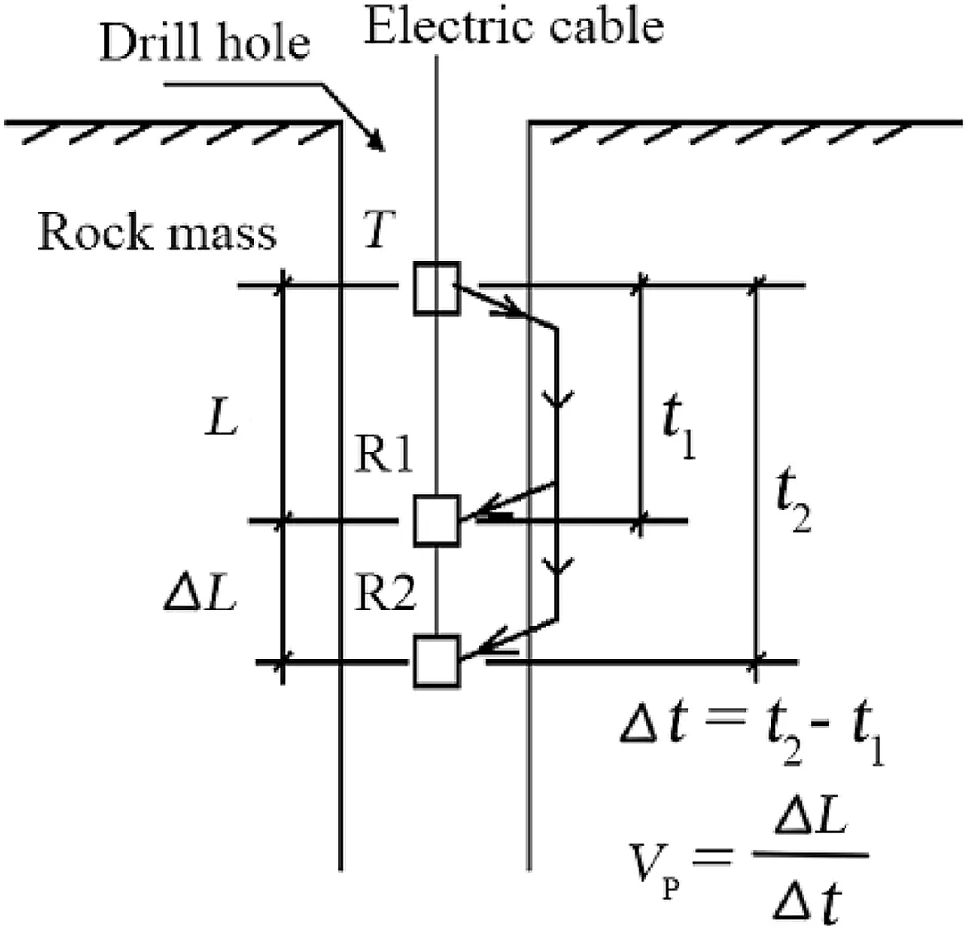
Fig.1.Schematic diagram of acoustic test principle.
Crack propagation and damage zone of rocks under blasting have been extensively investigated using numerical simulations.For instance,Hao et al.(2002a,b)simulated the stress wave propagation and damage zone in the rock mass induced by underground explosions using the equivalent material property approach and stochastic approach with AUTODYN3D,in which an anisotropic continuum damage model including both the statistical anisotropic initial damage and cumulative damage dependent on principal tensile strain and stochastic critical tensile strain was suggested.Xia et al.(2006)simulated the formulation and evolution of blast-induced cracks in rock using ANSYS/LS-DYNA programs,in which the sizes of crushed zone and fractured area were obtained.Fakhimi and Lanari(2014)proposed a numerical hybrid model using discrete element method and smooth particle hydrodynamic method to simulate rock blasting,and showed that the proposed hybrid model is capable of simulating the induced shock waves in the gas in association with wave propagation in the rock material.In addition,Trivino and Mohanty(2015)assessed the single-hole blast-induced damage in a granitic outcrop through controlled experiments and numerical simulations with a combined finite-discrete element method.
Because there are many uncertainties in the rock mass itself,it is rather difficult to understand the propagation regularity of blast induced seismic wave in advance(Wang and Yu,2001;Li et al.,2005).In general,the common approach to investigate wave propagation characteristics is using field monitoring data regressed by empirical formulae,such as Sadovsky formula(Northwood et al.,1963;Zong et al.,2008).
In this paper,the relationship between the PPV at a distance of 30 m away from the blast hole and charge per delay was derived based on Sadovsky formula in Fangchenggang nuclear power station.Meanwhile,the acoustic tests of rock mass before and after blasting were conducted to determine the damage depth of rock mass under blasting.The relationship between the PPV at a distance of 30 m away from the charge hole and damage depth of bedrock was put forward.A simple method based on safety threshold of vibration velocity for rock mass at 30 m away from the charge hole to restrict the damage depth of rock mass under blasting was presented.The remained bedrock can be simply and effectively protected during blasting using the proposed damage control method and the presented safety threshold of vibration velocity for rock mass.
2.Theories
2.1.Characteristics of wave propagation
According to theory of elasticity and wave theory(Li et al.,2009),it is assumed that the structural body vibrates due to the effect of disturbance.Thus we have

whereσis the stress in structural body under blasting;E is the elastic modulus;ε is the strain;and v and c is the particle vibration velocity and propagation velocity of vibration wave,respectively.
Substitution of Eq.(2)into Eq.(1)yields

It can be seen from Eq.(3)that the stress in structural body under blasting is proportional to particle vibration velocity.Therefore,the velocity of vibration can effectively reflect the blast induced damage.
In general,ground vibration velocity is related to the distance between the monitoring point and blasting source,R,and the charge per delay,Q.Several empirical relationships have been suggested to describe the attenuation of blast vibration wave,such as Eqs.(4)-(8)obtained by Duvall and Fogelson(1962),Langefors and Kihlstrom(1963),IS 6922(1973),Pal Roy(1991),and GB6722-2014(2014),respectively:
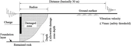
Fig.2.Damage control method in bedrock blasting excavation.
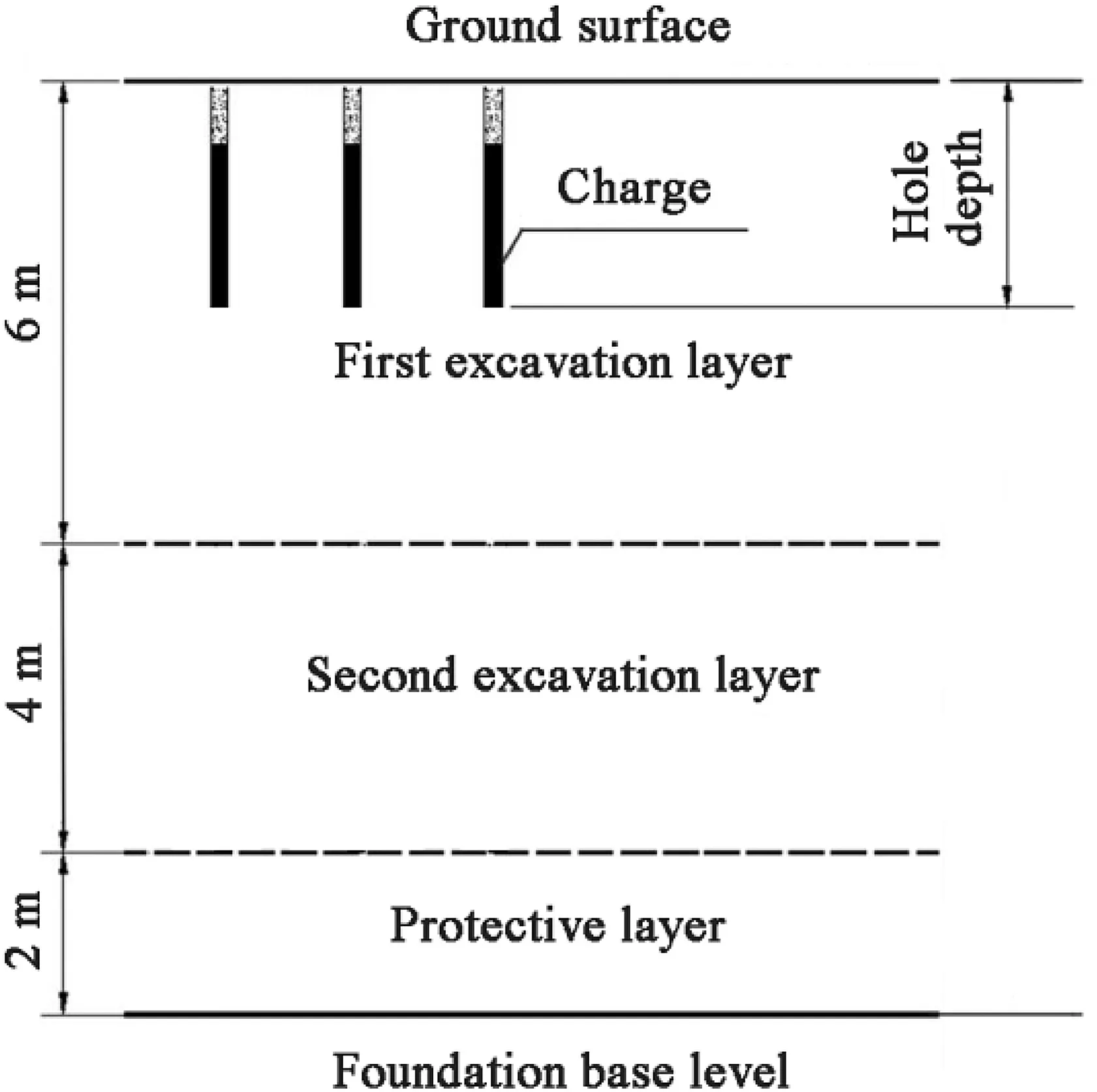
Fig.3.Excavation layers of nuclear island pit.


where SD=R/Q1/3is the scaled distance(m/kg1/3),K is a coefficient in blast design,αis the attenuation coefficient,and n is the parameter influenced by rock properties and geological discontinuities.In blasting practice,Eq.(8)pioneered by Dr.Sadovsky is widely used in China.
2.2.Acoustic test
The damage degree of rock mass can be evaluated in accordance with Chinese code DLT 5389-2007(2007):

whereηis the change rate of acoustic velocity and c0is the acoustic velocity of rock mass before blasting.It is believed that rock mass is critically damaged when the difference in acoustic velocities before and after blasting exceeds 10%.
Acoustic detection technique is widely used to evaluate the damage degree of rock mass.The mechanical properties degradation and blast-induced damage of rock mass can be obtained by measuring the variations in acoustic wave propagation properties.Fig.1 shows the principle of single-emission and double-receiving transducer(Li et al.,2005).In Fig.1,t1and t2are the acoustic travel times from transmitter T to receivers R1 and R2,respectively;Δt is the difference between t1and t2;ΔL is the distance from receiver R1 to receiver R2;and VPis the P-wave velocity in rock mass.
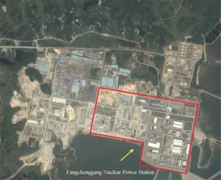
Fig.4.Satellite map of Fangchenggang nuclear power station.
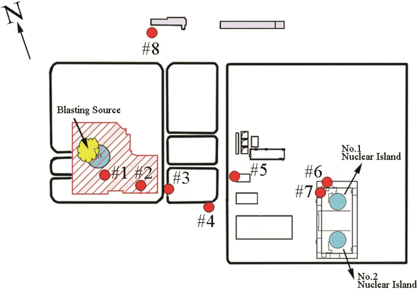
Fig.5.Layout of vibration monitoring points.
2.3.Relationship between blast-induced damage zone and peak particle velocity
During blasting excavation,damage to surrounding rocks is suggested to be caused by stress wave propagation and gas expansion.However,there are difficulties in directly measuring the dynamic response of rock mass in the near field of explosion source.The current approach is to measure the vibration velocity or acceleration of the rock mass at a certain distance away from the explosion source,making sure that the corresponding vibration velocity or acceleration does not exceed a specified limit.
According to the construction experiences gained from the nuclear power stations in China,such as Ling’ao,Ningde and Hongyanhe,the practical method for damage control of bedrock under blasting is to control the PPV of rock mass at a certain distance(basically 30 m)away from the explosion source,which does not exceed a certain limit value(safety threshold).The reason for selecting the PPV at 30 m away from explosion source is that the distance of 30 m between the monitoring point and explosion source is generally located in the area between the near field and far field of explosion source.If the monitoring instrument is installed too close to the explosion source(such as 3 m),the monitoring instrument will be destroyed by flying rocks and shock wave.The closer the measurement distance is,the more sensitive the vibration velocity is to various factors of rock mass explosion,resulting in more dispersivity of monitoring data.However,if the monitoring instrument is placed too far from the explosion source(e.g.300 m),the amplitude of blast vibration signal will become weaker and the influences of geology,topography and inhomogeneity of rock mass on blast vibration signals are greater than that of the smaller monitoring distance(e.g.30 m),which is also not conducive to the analysis and formulation of the control standard of vibration velocity.
The damage depth of rock mass and attenuation of blast vibration wave have been systematically analyzed by Xia(2006)and Xie(2010)at Ling’ao and Ningde nuclear power plants,respectively,by means of blast vibration monitoring,acoustic test and numerical simulation.In their numerical simulation,the blast loading was calculated by ANSYS/LS-DYNA and then input into the FLAC3D and 3DEC models respectively to analyze the characteristics of rock mass damage and the attenuation of blast vibration wave.Combining the site monitoring data and numerical results,the relationship between the damage depth of bedrock and PPV at 30 m away from the explosion source was obtained.One can see that a high positive correlation existed in that relation.In terms of safety control methods and standards for bedrock blasting in nuclear power project,an effective method to control the damage depth of rock mass was proposed,i.e.controlling PPV at 30 m away from explosion source.The schematic diagram of damage control method in bedrock blasting excavation is shown in Fig.2.
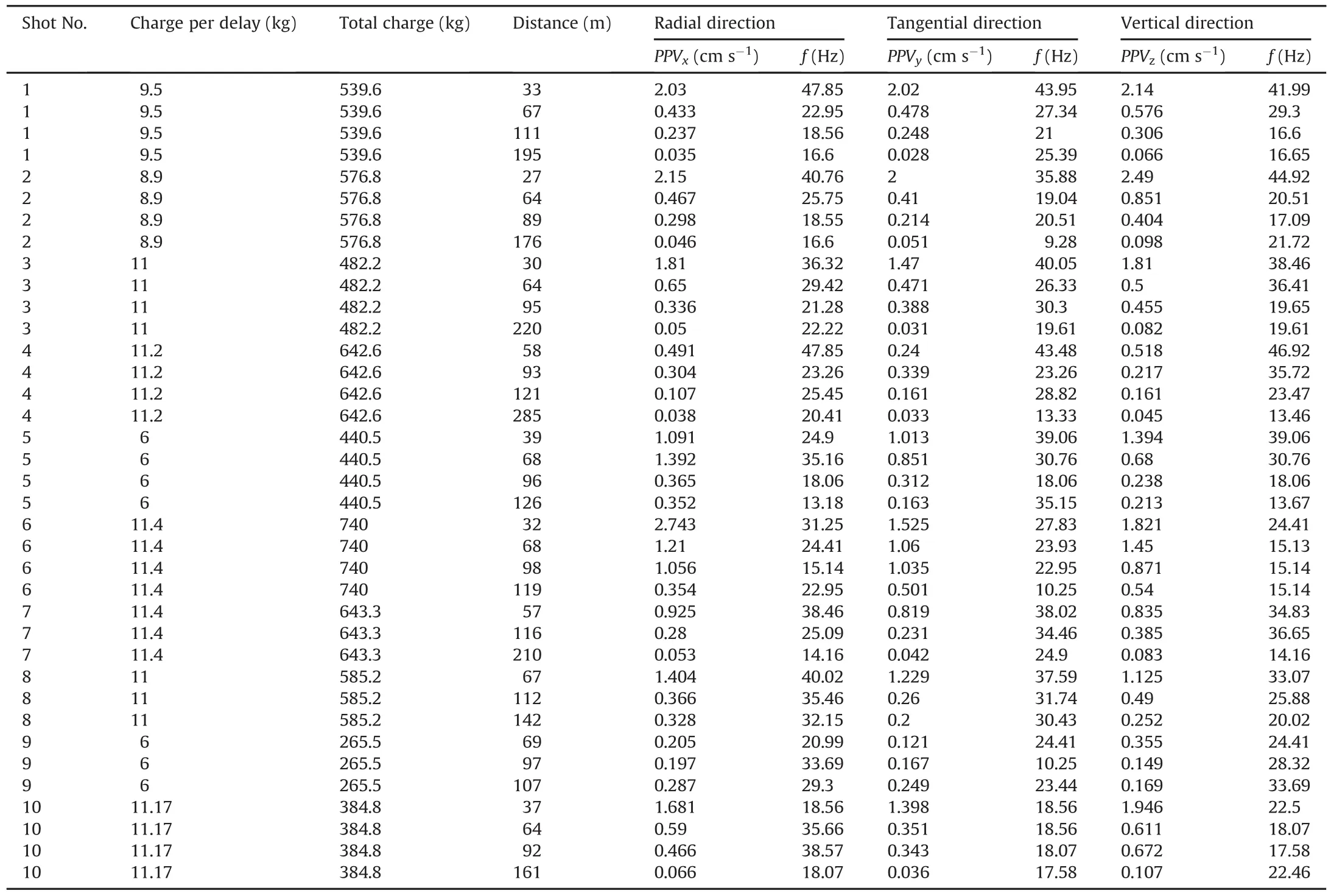
Table 1Monitoring results of peak particle velocity under explosion.
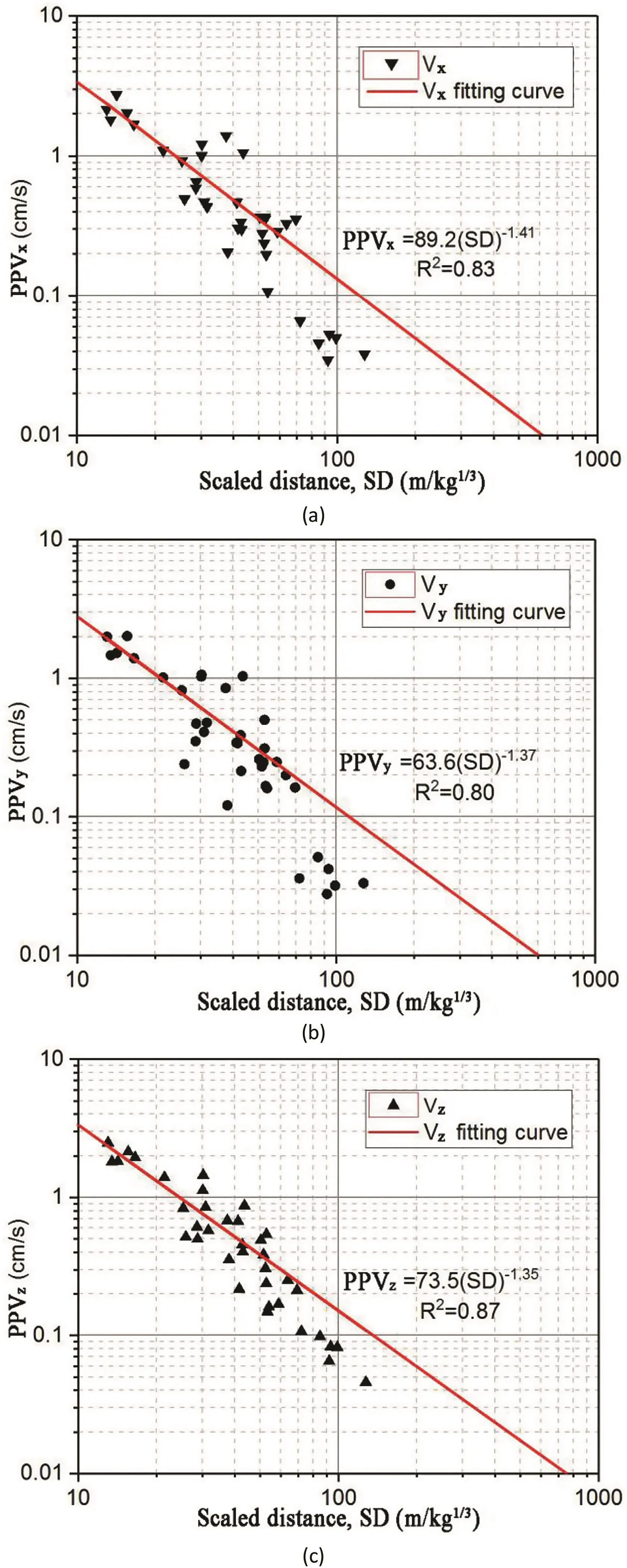
Fig.6.Regression results of the peak particle velocity and scaled distance in(a)radial,(b)tangential,and(c)vertical directions.
As illustrated in Fig.2,the blast-induced wave propagates in rock mass from the charge hole and causes damage to surrounding rocks in vertical and radial directions.The integrity of remained rock mass beneath the foundation should be strictly controlled to meet the requirement of bedrock foundation of the nuclear power plant.The allowable damage depth is usually defined as the limited length varying from 0.25 m to 2 m,which must be less than the distance between the bottom of the charge hole and the top face of foundation.The safety threshold of vibration velocity is defined as the limit of PPV at a distance of 30 m away from explosion source,which generally ranges from 1.5 cm/s to 5 cm/s(Xia et al.,2006,2010;Xie et al.,2009).
The excavation layers of the Fangchenggang nuclear island pit is shown in Fig.3.The pit is approximately 12 m deep and excavated in three layers.The depths of the first and second layers are 6 m and 4 m,respectively.The third layer called protective layer is excavated by blasting with air column of 0.25 m deep at the bottom of the blast hole to protect the remained rock mass beneath the bedrock foundation.The allowable damage depths for the first,second and third layers are designed to be 2 m,1.5 m and 0.25 m,respectively.To guarantee the integrity of the remained rock mass beneath the foundation base level,the safety threshold of vibration velocity(PPVlimit)at a distance of 30 m away from explosion source is strictly controlled.
3.Case study
3.1.Brief introduction
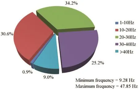
Fig.7.Frequency distributions of blast vibrations.
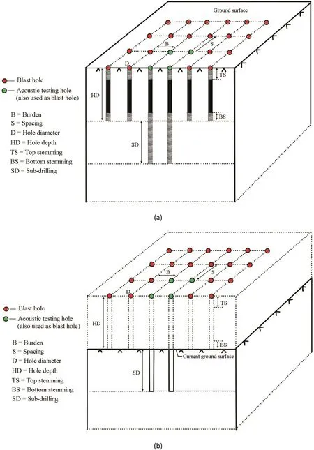
Fig.8.Arrangement of acoustic testing holes(a)before and(b)after blasting.

Table 2Blasting parameters used on site with acoustic tests for bedrock excavation.
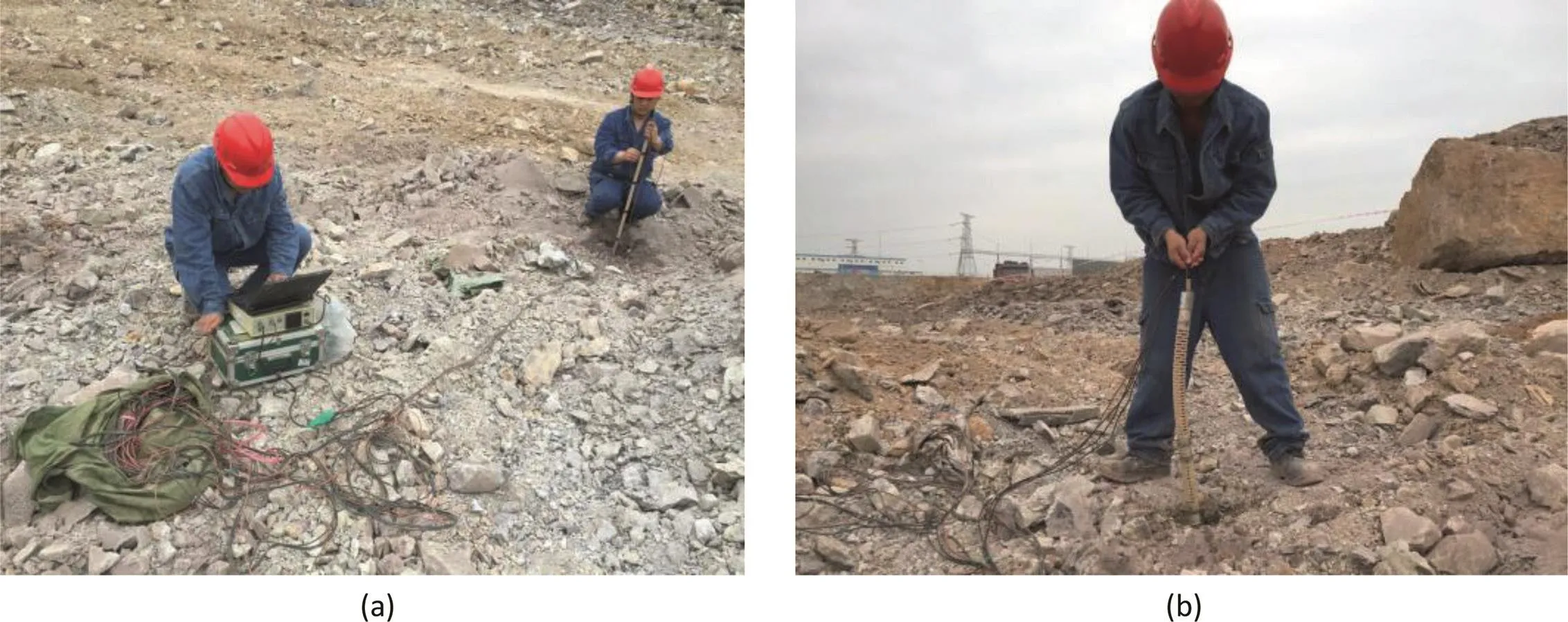
Fig.9.Photos of acoustic test on site:(a)Testing process and(b)Installation of single-emission and double-receiving transducer.
The Fangchenggang nuclear power station is located in Fangchenggang City,Guangxi Zhuang Autonomous Region,China.In the construction site,blasting seismic monitoring and acoustic tests were conducted to understand the bedrock damage.The satellite map of the Fangchenggang nuclear power station and layout of blast vibration monitoring points are shown in Figs.4 and 5,respectively.
3.2.Monitoring and analysis of blast vibration signals
A total of 111 blast vibration data sets in radial,tangential,and vertical directions were recorded from 37 blasting monitoring points of 10 shots that used bench blasting and controlled blasting.The monitoring results of PPV under blasting are listed in Table 1.These data are selected to fit the power function of Eq.(8)for bedrock blasting excavation.The regression results of the PPV and scaled distance,SD,in radial,tangential and vertical directions are shown in Fig.6,and are expressed as
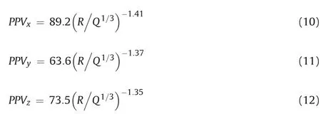
The blast-induced wave propagation velocities can be obtained using Eqs.(10)-(12).Then the charge per delay,Q,in the blast design can be obtained according to the allowable PPV limit,
PPVlimit,at different distances away from the charge hole,R,to meet the requirement of damage depth for different layers of rock excavation.The allowable PPV limit,PPVlimit,of ground vibration is defined by the maximum value of three components:

In the Sadovsky empirical formula,the coefficient K is directly proportional to PPV.The larger the coefficientαis,the faster the velocity attenuation along propagation direction is(Zong et al.,2008;Lu et al.,2009).By comparing the differences ofαand K in radial,tangential and vertical directions,it can be observed that the coefficients K andαin radial direction are the largest,which shows that the velocity attenuation in radial direction is the fastest.Even though the PPV in radial direction is generally larger than that in tangential and vertical directions in the near field of explosion source,the PPV in radial direction will be lower than that in tangential and vertical directions in the far field of explosion source.This is consistent with the results listed in Table 1.Thus it is noteworthy that we should consider the components of PPV in three different directions rather than a single direction as safety criterion for blast vibration control.
The frequencies of the recorded blast vibration are shown in Fig.7.Previous studies have shown that the vibrationfrequencyand velocity both play a significant role in vibration-induced rock damage.The natural frequencies of buildings roughly range between 2 Hz and 5 Hz,thus high-frequency vibration is beneficial to structural safety and surrounding rock stability for reducing the probability of resonance(Li et al.,2009;Zong et al.,2013).According to the standards of the United States Bureau of Mines(USBM),frequencies less than 40 Hz are classified as low frequencies(Siskind et al.,1980).As shown in Fig.7,a major part of the recorded frequencies is between 10 Hz and 40 Hz.Damage potentials for low-frequency blasts(<40 Hz)are considerably higher than those for high-frequency blasts(>40 Hz).It can be seen in Fig.7 that although the frequency values of 1-10 Hz having higher damage risk only account for 0.9%of all shots,90.1%of the frequency values are between 10 Hz and 40 Hz.Hence,it can be said that the blasting site of bedrock excavation can be classified as a low-frequency site and the measured frequencies at this site are of high-potential damage risk.
3.3.Acoustic test results
Six groups of field acoustic tests were carried out to investigate the rock damage.The damage depth and characteristics of the bedrock under blasting were determined by comparing the variations of the wave velocities in each depth range.As shown in Fig.8a,four charge holes in each group with approximately 3 m subdrilling were chosen as acoustic testing holes.Before and after blasting,single-hole acoustic tests were performed to study the acoustic velocity in rock mass in the sub-drilling section(Fig.8b).
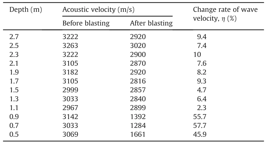
Table 3Results of acoustic test for the first hole in group 1.
Blasting parameters used on site with acoustic tests for bedrock excavation are listed in Table 2.The photos of acoustic test on site are shown in Fig.9.
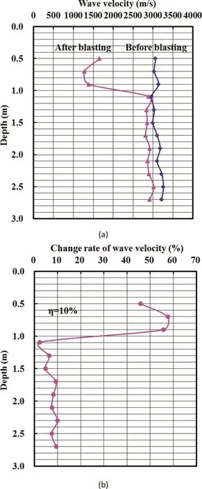
Fig.10.(a)Wave velocity and(b)its change rate for the first hole in group 1 before and after blasting.
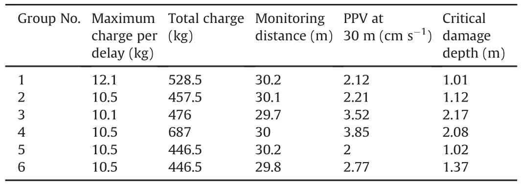
Table 4Results of blast vibration monitoring and acoustic test.
Before blasting,the acoustic test was carry out in the corresponding testing holes to obtain the acoustic velocity.The acoustic test procedures are described as follows:
(1)Fill the acoustic testing hole with water first.Then place the single-emission and double-receiving transducer tube into the bottom of the hole and set the test parameters.
(2)Select the stable test waveform and record.Then move the test tube upwards at an interval of 0.2 m,and repeat recording until all testing hole sections are completed.
(3)Fill the sub-drilling part of testing holes with stemming to reach average charge design depth,and then insert all the blast holes and testing holes with bottom stemming,explosive charge and top stemming.
(4)After blasting,the sub-drilling part of testing holes is drilled again.Then the acoustic test is performed to obtain the acoustic velocity after blasting.
Taking the acoustic test of the first hole in group 1 for example,the results are listed in Table 3.
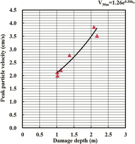
Fig.11.Relationship between damage depth of bedrock and peak particle velocity at a distance of 30 m away from the charge hole.

Table 5V30 mand charge per delay calculated based on Eqs.(10)-(12)and(14).
The acoustic velocity and its change rate for the first hole in group 1 before and after blasting are shown in Fig.10.According to Chinese code DLT 5389-2007(2007),it is suggested that rock mass is critically damaged when the change rate of acoustic velocity before and after blasting is larger than 10%.In Fig.10,we can see that the critical damage depth of the first hole in group 1 is 1.05 m,and the critical damage depths of other three holes in group 1 are 0.91 m,1 m and 1.08 m,respectively,with the average value of 1.01 m for the four holes in group 1.Six groups of acoustic test results including critical damage depth,blast design parameters and PPV at a distance of 30 m away from the charge hole are listed in Table 4.The relationship between PPV at a distance of 30 m away from the charge hole and critical damage depth is presented in Fig.11 and can be expressed as

where V30mis the PPV at a distance of 30 m away from the charge hole(cm/s),and hDis the critical damage depth of bedrock(m).Thereby,we can obtain V30mand charge per delay according to the requirement of damage depth for different layers of excavation using Eqs.(10)-(12)and(14).For example,if the allowable damage depth is 2 m,the corresponding V30mwill be 3.43 cm/s derived from Eq.(14)and the charge per delay will be restricted as 26.3 kg derived from Eqs.(10)-(12).
The safety threshold of V30mand charge per delay calculated based on Eqs.(10)-(12)and(14)are listed in Table 5,which shows that the allowable charge per delay is controlled by that in radial direction.Because the allowable damage depths of the first,second and third excavation layers are designed to be 2 m,1.5 m and 0.25 m,respectively,the allowable V30mare set as 3.43 cm/s,2.67 cm/s and 1.43 cm/s,respectively,and the charge per delay should be restricted within 26.3 kg,15.5 kg and 4.1 kg,respectively,in order to effectively control the blast-induced damage of bedrock.In Fangchenggang nuclear power station,it is essential to strictly control the charge per delay and total charge based on above calculation results.In the subsequent process of rock blasting,we have achieved excellent effect on blasting control.
4.Conclusions
Blast vibration monitoring and acoustic tests were carried out during the bedrock blasting excavation in Fangchenggang nuclear power station.The blast-induced wave propagation and damage characteristics in rock mass were analyzed in this study.The method to control the bedrock damage zone in blasting excavation was proposed,i.e.restricting the threshold of V30mand the charge per delay.The main conclusions are drawn as follows:
(1)The equations to describe wave propagation characteristics in radial,tangential and vertical directions are derived using Sadovsky empirical formula.It is noteworthy that we should consider the PPV components in three different directions rather than a single direction as safety criterion for blast vibration control.
(2)The relationship between V30mand damage depth of
bedrock in Fangchenggang nuclear power station can be written asV30m= 1:26e0:5hD,which is obtained by conducting blasting seismic monitoring and acoustic tests before and after blasting in order to control the damage depth of rock mass under blasting.
(3)Based on the blast-induced wave propagation,we can properly select the charge per delay for blast design.In the blasting excavation of the first,second and third layers of nuclear island pit,the allowable V30mvalues are 3.43 cm/s,2.67 cm/s and 1.43 cm/s,respectively,and the charge per delay should be restricted as 26.3 kg,15.5 kg and 4.1 kg,respectively.
Conflicts of interest
The authors wish to confirm that there are no known conflicts of interest associated with this publication and there has been no significant financial support for this work that could have influenced its outcome.
Acknowledgements
The study was supported by the Key Program of National Natural Science Foundation of China(Grant No.51439008),National Natural Science Foundation of China(Grant Nos.41572307 and 51779248),and National Natural Science Funds for Distinguished Young Scholar of China(Grant No.41525009).The authors are also very grateful to the editors and anonymous reviewers for valuable suggestions which have improved the quality of this paper.
 Journal of Rock Mechanics and Geotechnical Engineering2018年5期
- Journal of Rock Mechanics and Geotechnical Engineering的其它文章
- Pullout behavior of polymeric strip in compacted dry granular soil under cyclic tensile load conditions
- A comparative study between gravel and rubber drainage columns for mitigation of liquefaction hazards
- Bearing behavior and failure mechanism of squeezed branch piles
- Experimental evaluation of mechanically stabilized earth walls with recycled crumb rubbers
- Dynamic properties and liquefaction behaviour of cohesive soil in northeast India under staged cyclic loading
- Saturated anisotropic hydraulic conductivity of a compacted lateritic soil
