A comparative study between gravel and rubber drainage columns for mitigation of liquefaction hazards
Hadi Bahadori,Roohollah Farzalizadeh,Ali Barghi,Araz Hasheminezhad
Department of Civil Engineering,Urmia University,Urmia,Iran
Keywords:Liquefaction Soil improvement Drainage columns Shaking table test
A B S T R A C T Liquefaction is one of the most destructive natural hazards that cause damage to engineering structures during an earthquake.This study aims to examine the effect of rubber and gravel drainage columns on the reduction of liquefaction potential of saturated sandy soils using a shaking table.Experiments were carried out in various conditions such as construction materials,different arrangements and diameters of drainage columns.Effects of the relative density and the input motion on the base test were investigated as well.The results demonstrate that rubber drainage columns have slightly better performance compared to gravel drainage columns at high relative density and high input acceleration.Soil improvement using gravel drainage columns,which leads to reduction in liquefaction effects at moderate input acceleration and low relative density,is a more effective method than that using rubber drainage columns.By increasing the number and diameter of gravel and rubber drainage columns,deformations due to liquefaction are reduced.The drainage rate of gravel drains is higher than that of rubber drains after shaking.Totally,the outcomes indicate that densification is the most important factor controlling liquefaction.
1.Introduction
Liquefaction of sandy soils is one of the challenging issues in geotechnical engineering.Whenever loose saturated granular soils are exposed to cyclic loadings,they tend to decrease in volume,which produces an increase in their pore water pressures and consequently a decrease in shear strength.One of the methods to mitigate the damaging effects of earthquake-induced liquefaction is to provide rapid dissipation of excess pore pressures applying vertical drains through the liquefiable materials.When the pore pressures dissipate rapidly,the effective stress will not be significantly reduced,and liquefaction will not occur.Applying drains with high permeability leads to foresaid result.
Seed and Booker(1977)introduced drainagetechniques employing stone columns(gravel drains).They carried out field research using the gravel drainage system toprevent liquefaction of the soil under structural engineering.Out performance of the drainage columns was proven during the earthquakes in Japan in the 1990s.Then prefabricated vertical drains(PVDs)have been used for liquefaction remediation(JGS,1998).
Sasaki and Taniguchi(1982)conducted shaking table tests to examine the effects of partial-depth drains on a roadway.In their particular configuration,they indicated that pore pressures remained elevated for a longer period when their drains did not reach the model base compared to that when they were full-depth.The model in this case was very shallow and liquefaction would be anticipated at the base in the unremediated model.
The use of stone columns in silt deposits was examined by Adalier et al.(2003),who found that the primary effect was to increase the stiffness of the soil mass during cyclic loadings,leading to a reduction in the shear strains and thus the generation of excess pore water pressure.
Brennan and Madabhushi(2006)examined the liquefaction modification by vertical drains with different depths of penetration applying centrifuge tests.The results showed that deeper soils benefit from the presence of drains more quickly.They also observed that the additional burden placed on the deep penetrating drains prevented them from operating efficiently.Moreover,they indicated that a standard design chart may overpredict an improvement in drain performance.
Geng et al.(2012)presented analytical methods for a single vertical drain with vacuum and time-dependent preloading in membrane and membraneless systems.These methods enhanced the accuracy of estimating pore water pressure dissipation and associated settlement.Howell et al.(2012)presented centrifuge modeling of PVDs for liquefaction remediation.The results revealed that drains were effective in expediting the dissipation of excess pore water pressures and decreasing deformations.Wang et al.(2015)showed that soil improvement with stone columns has a significant influence on the mitigation of liquefaction hazards.Rasouli et al.(2016)examined liquefaction modification by drainage pipes and their combination with sheet-pile walls in different groundwater levels utilizing shaking table tests.The results indicated that the settlement of the structure cannot be reduced significantly unless there is a perfect nonliquefied layer under the foundation of structure.Huang et al.(2016)demonstrated that the effectiveness of gravel columns for mitigation of soil liquefaction during an earthquake depends on the following three aspects:(1)the densification of the surrounding soils,(2)drainage along the stone column,and(3)reduction in the total cyclic shear stress of the soil(because the cyclic shear stress is partially shared by the stone column).Salem et al.(2017)indicated that considering the densification and stiffening effects considerably improves the assessment of liquefaction potential of reinforced soil by drainage columns.
Miranda et al.(2017)studied the influence of the geotextile encasement on the behavior of soft soils improved by fully penetrating encased columns.Their results illustrated that pore pressures dissipate faster in samples with encased stone columns compared to those with non-encased columns,and the reduction of settlements is higher when the column is encased.
Waste material expulsion is one of the environmental issues faced in many countries.Accumulation of non-degradable polymeric materials in land fills has serious environmental consequences.Only a few percentages of scrap tires are burned to produce electricity.Efforts to find new ways of soil improvement and reinforcement have drawn attention of researchers towards the use of new recycled materials like scrap tires derivatives.
Derivatives of scrap tires have different applications in civil engineering such as reinforcing soft soil(Anvari et al.,2017;Yadav and Tiwari,2017),as a drainage layer in land fills(Kaushik et al.,2016),as filler materials(Assadollahi et al.,2016),as lightweight material for back filling in retaining structures(Shrestha et al.,2016),for vibration isolation(Hadad et al.,2017),and in reinforced concrete(Guo et al.,2017).In spite of the widespread utilization of tire chip in geotechnical engineering,its application to liquefaction mitigation is not yet fully developed.
Bahadori and Farzalizadeh(2018)examined the effects of adding scrap tires on the liquefaction potential and the dynamic properties of loose saturated sandy soil.Their results demonstrated that excess pore water pressure and settlement due to liquefaction significantly decrease with increasing percentage of tire powders.In addition,they observed that the mean damping ratio and shear modulus increase in the reinforced models.
Based on the literature review,it appears that further studies are required to assess the performance of soil improved with rubber drains on reducing liquefaction potential.In this paper,the shaking table test results for improvement of sand with rubber and gravel drainage columns are presented.
2.Physical model
2.1.Shaking table and instrumentation
The shaking table and the positions of utilized instruments are demonstrated in Fig.1.The container has inner dimensions of 2000 mm×500 mm×700 mm(length×width×height).A plastic plate was rigidly fixed and sealed carefully at the center of the container to separate improved models with gravel and rubber drains.The shaking table is designed to resonate at a frequency of around 2 Hz.The input shaking in all tests was a one-dimensional(1D)and harmonic sinusoidal wave.The dynamic loadings used for this study were not meant to be representative of actual earthquake ground motions.Contrary to real earth quakes,the applied vibration was 1D,of approximately uniform amplitude,and constant frequency.These loading conditions allowed for a good observation of the dynamic behavior of the materials and relative comparisons of their responses.Similar types of loadings have been frequently used in other liquefaction researches(Pépin et al.,2012;Bahadori and Manafi,2015).
Different types of transducers were used to measure acceleration,pore water pressure,and displacement at different positions.The pore pressure transducers were fixed in a spot to monitor the pore water pressure in exact locations.The acceleration transducers were fixed on the base to avoid tilting during test and were free to move with the adjacent soil.The linear variable differential transducers(LVDT)LVDT1 and LVDT2 were installed at the ground surfaces of samples,improved with rubber drainage columns and gravel drainage columns,respectively.
The shaking table container is rigid;it is obvious that boundary conditions could affect the test results.Thus,a 2-cm thick absorbing layer of foam was employed in shaking direction of the container(Lombardi et al.,2015).Moreover,an attempt was made to reduce its effect by band filtering data(acceleration raw data)to eliminate some of the erroneous data.

Fig.1.Model and instrumentation(dimension:mm).
2.2.Materials
2.2.1.Soil
Firoozkuh sand,which is a uniform clean sand,was applied in this experimental investigation(Bahadori et al.,2008).According to the unified soil classification system(USCS),it can be classified as a poorly graded sand(SP).
2.2.2.Drainage materials
The materials used in drainage columns must have high permeability to decrease the liquefaction potential.Seed and Booker(1977)illustrated that the drain operates perfectly,providing it has the permeability of the order of 200 times that of the sand.In this study,tire chips and gravel were used to fabricate drains.Tire chips were obtained from crushing waste tires by an industrial tire-shredder system.Fig.2 illustrates the particle size distribution of soil and drainage column materials.Table 1 and Fig.3 depict the mechanical properties of the materials used and a view of the drainage materials,respectively.
By increasing the size of drainage materials and reducing fine particles,drainage hydraulic conductivity increases.Nevertheless,as the void space between the particles increases,the potential for clogging is also increased.This is due to filling of the void space of the drainage materials with soil particles which decrease the permeability of the drains.To avoid clogging,the relationship between the gradation of surrounding soil and the drainage materials,proposed by the Japanese Large Dam Conference(Orense et al.,2003),has been used:

where DG15is the grain size of the drainage materials corresponding to 15% finer by weight,and DS85is the grain size of the surrounding soil corresponding to 85% finer by weight.
2.3.Model preparation
Relative density of the sand is calculated by the following relation:

where es,emaxand emindenote the sand void ratio,maximum and minimum sand void ratios,respectively.

Table 1Specifications of materials.
The moist tamping technique was used to prepare models.This method is one of the most commonly used methods in laboratory researches for soil reinforcement.It allows any soil sample to be prepared within a wide range of relative densities(Bahadori and Farzalizadeh,2018).In each model,the soil profile was divided into six identical layers.The required weight of each layer was calculated based on the desired relative density,which in this study is set to 0%and 30%.Soil was uniformly placed in the surface of the box.Then,each layer was compressed to achieve a specific density.
The 1g shaking table model tests cannot be carried out under high confining pressures like that of in situ,but to imitate in situ conditions,they are conducted on models of the same in situ density.The results of a series of undrained triaxial compression tests showed that very loose sand under low confining pressure has similar softening behavior,which leads to disastrous flow failure,compared to sand with a higher relative density conducted under relatively higher confining pressure(Verdugo and Ishihara,1996).Therefore,it has been recommended to utilize extremely loose sand in shaking table tests,substantially looser than in situ sand,so that the impact of reduced stress is recovered by the decreased relative density(Towhata,2008).
Deformation of sand during the shaking can be visualized by implementing a square grid of colored sand.Carbon dioxide gas was allowed to pass through the sample at low pressure in order to replace the air trapped in the pores of the sample.Finally,water was permitted to flow upward through the bottom of the container at low pressures in order to flush out the carbon dioxide which causes the final degree of saturation to increase.The floor of the container was covered with a fine-sieve mesh(sieve No.200)so that the saturation process could be done gradually and uniformly.The mentioned method has been used before by other researchers(Towhata et al.,2009)in physical modeling tests.
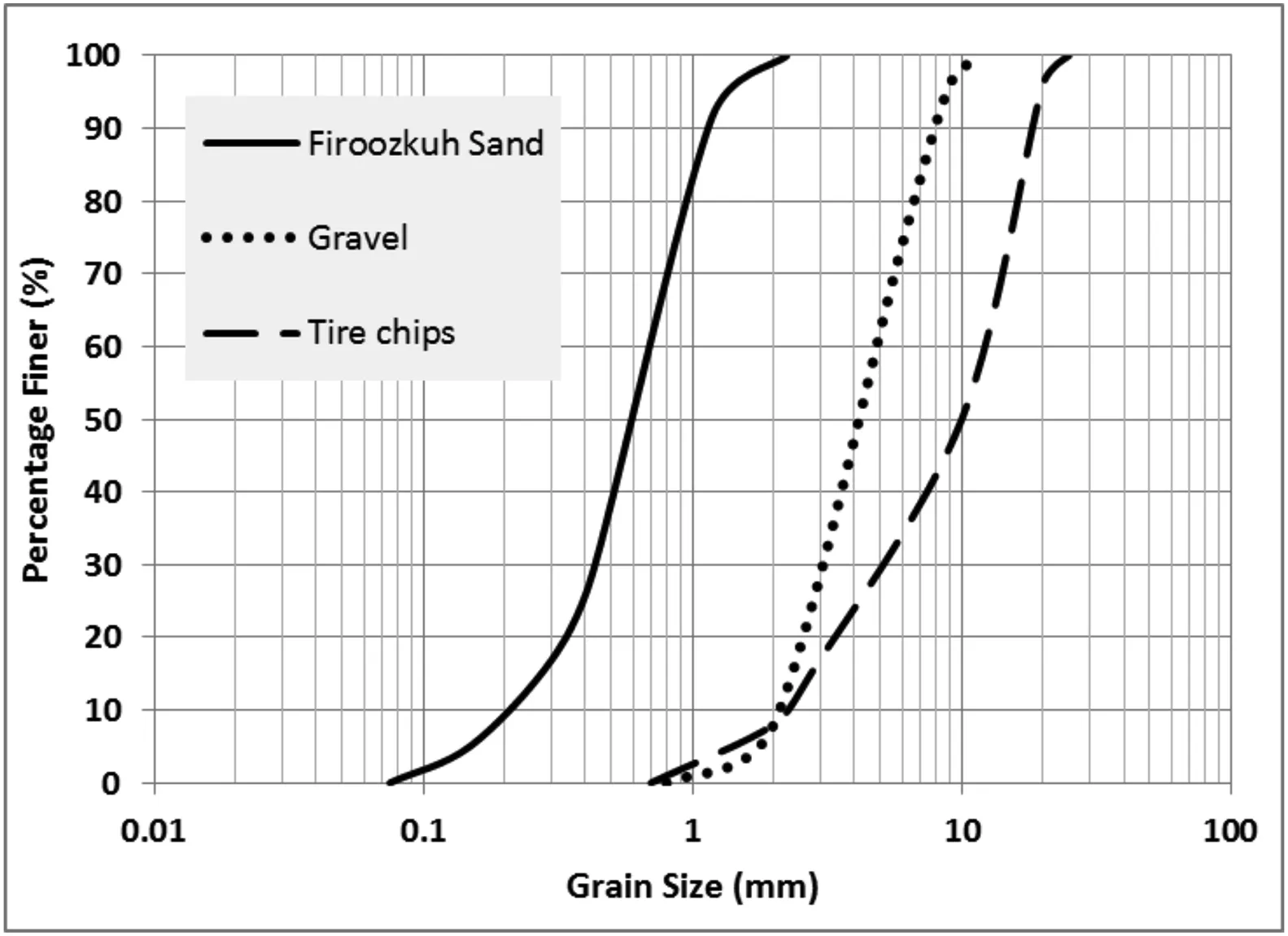
Fig.2.Grain size distribution curves of materials used in the tests.
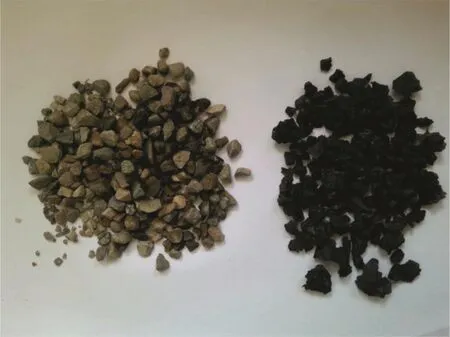
Fig.3.View of gravel(left)and tire chips(right)used.
A procedure was needed to fabricate the drainage columns with high quality control.The construction of these columns within the modeled sand layer was considered infeasible.Due to this,PVC(polyvinyl chloride)pipes were used to model the rubber and gravel drains(Huang et al.,2016).First,the PVC pipes were placed with high precision within the model container before the surrounding sand layer was constructed.Then,the sand was spread into the container and each sand layer was densified.When the modeling of soil was finished,the drainage columns surrounded with geotextile encasement were placed inside the PVC pipes.Although utilized geotextile( fine mesh)passes water flow,it prevents the entry of soil particles into drainage columns.At final stage,the pipes are removed.Fig.4 portrays the construction process of the models.
2.4.Method of shaking table tests
To calculate the spacing of the drains(Table 2),the charts prepared by Seed and Booker(1977)were used.These charts consider the consolidation properties of the liquefiable soil,the pore pressure generated model,the expected earthquake loading,and the allowable excess pore pressure ratio.
Generally,six experiments were conducted on the sand improved with drainage columns.The sand with gravel drainage column was placed on one side,and the sand with rubber drainage column was placed on the other side of the box.Details of the model tests are presented in Table 3.In this study,core parameters method(Fakher,2014)was employed to examine the various parameters.In this method,the parameters used in the tests are determined according to previous research.A base test is introduced(test a).In fact,this method investigates the effect of each parameter on the base test.In each test,only one parameter is changed and the other parameters keep constant.In this method,by developing six experiments,the effects of the number of drains,drain diameter,relative density of soil,and input acceleration of samples with gravel and rubber drainage columns were investigated.Moderate and high peak input accelerations(A5)are about 0.25g and 0.45g,respectively(Kramer,1996).Fig.5 shows the arrangement of drainage columns.
3.Experimental results
3.1.Time history of acceleration
Figs.5 and 6 depict the time histories of the measured accelerations and base excitations of tests a-f at certain depths of samples(z=20 cm and 40 cm).Outcomes show that the base acceleration amplitude(A5)was increased through transmission to the ground surface until liquefaction occurred.Rearrangement of soil particles due to the transmission of seismic motion through layers can cause instantaneous build-up of excess pore water pressure in the surface layers of the soil,leading to a reduction in the shear stiffness of saturated soil.As a result,liquefaction changes acceleration trend and acceleration within the soil tends to decrease towards the soil surface(see Fig.7).
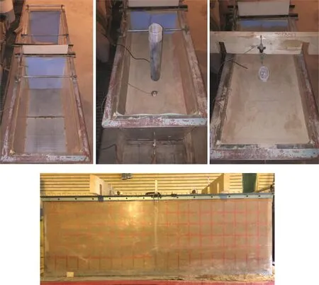
Fig.4.Construction process of the models.

Table 2Design of drainage columns.

Table 3Details of the model tests.
The first result obtained from Figs.5 and 6 is that the peak acceleration increases while propagating from base to ground surface in samples of tests b(N=4),c(N=3),and d(Dr=30%).It is clear that the increases in diameter and number of drains lead to reduction of the length of drainage path which prevents soil softening and liquefaction.Moreover,in test d,moderate input acceleration cannot create softening in 20 s due to the high shear strength of the soil.Nevertheless,acceleration within upper layers of soil(at points A1 and A3)tends to decrease in the improved samples of tests a(base test),e(high input acceleration),and f(2A=2 inch),as a consequence of the softening of liquefied shallow layers.At high shaking mode(test e),this reduction is created after a fewer number of cycles.In fact,fewer cycles are required to induce liquefaction at high input acceleration compared to moderate input acceleration.
3.2.Time history of pore water pressure
Pore water pressure is one of the most important factors in examining the seismic behavior of saturated soils.Fig.8 illustrates the time histories of the excess pore water pressure ratio(Ru= Δu/σ′0)of improved models for tests a-f.It should be noted that Δu is the excess pore water pressure and σ′0is the initial vertical effective stress at points P1 and P2(improved models with rubber drains(Ru1)and gravel drains(Ru2)).
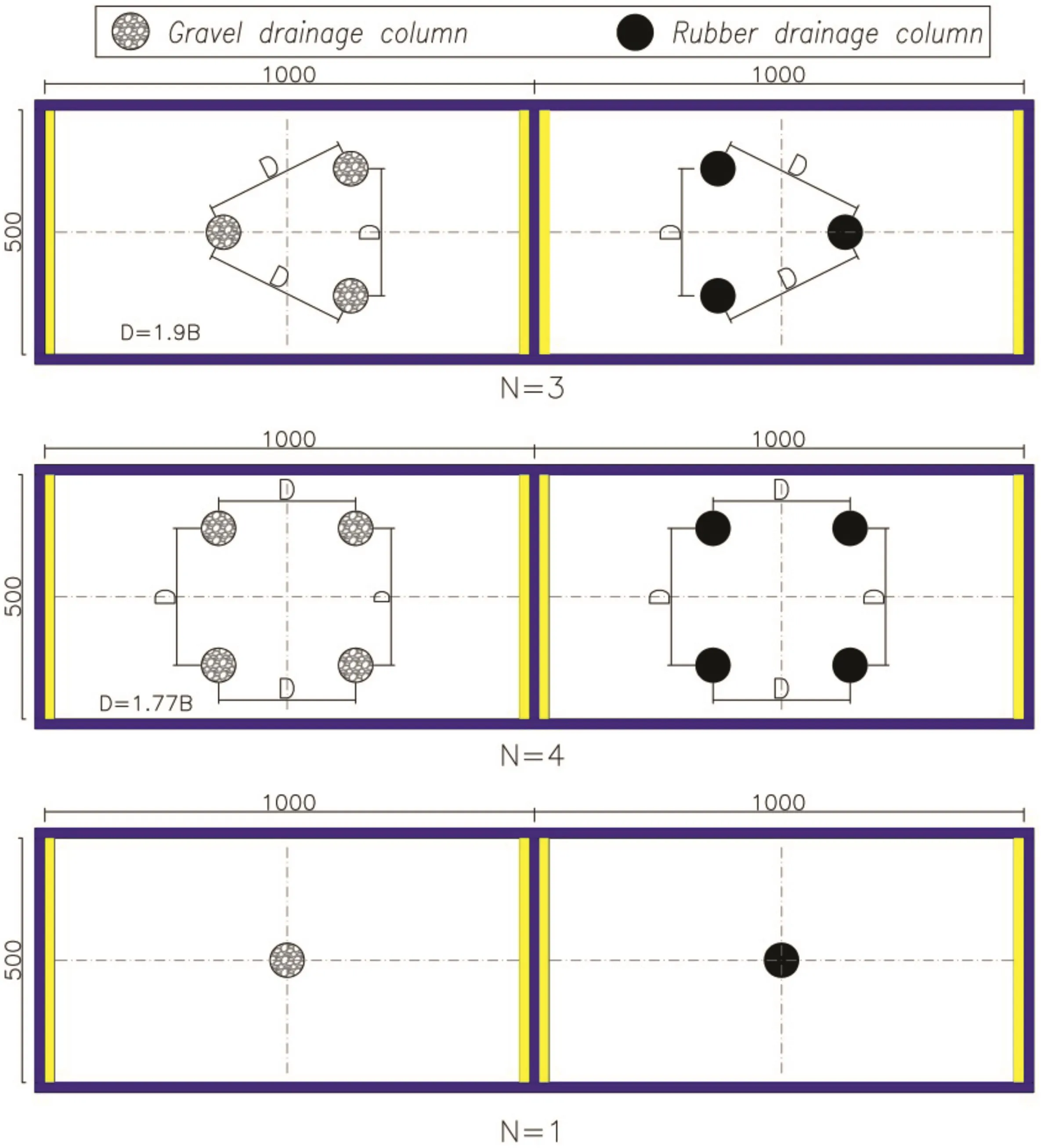
Fig.5.Plan view of arrangement of drainage columns(dimension:mm).
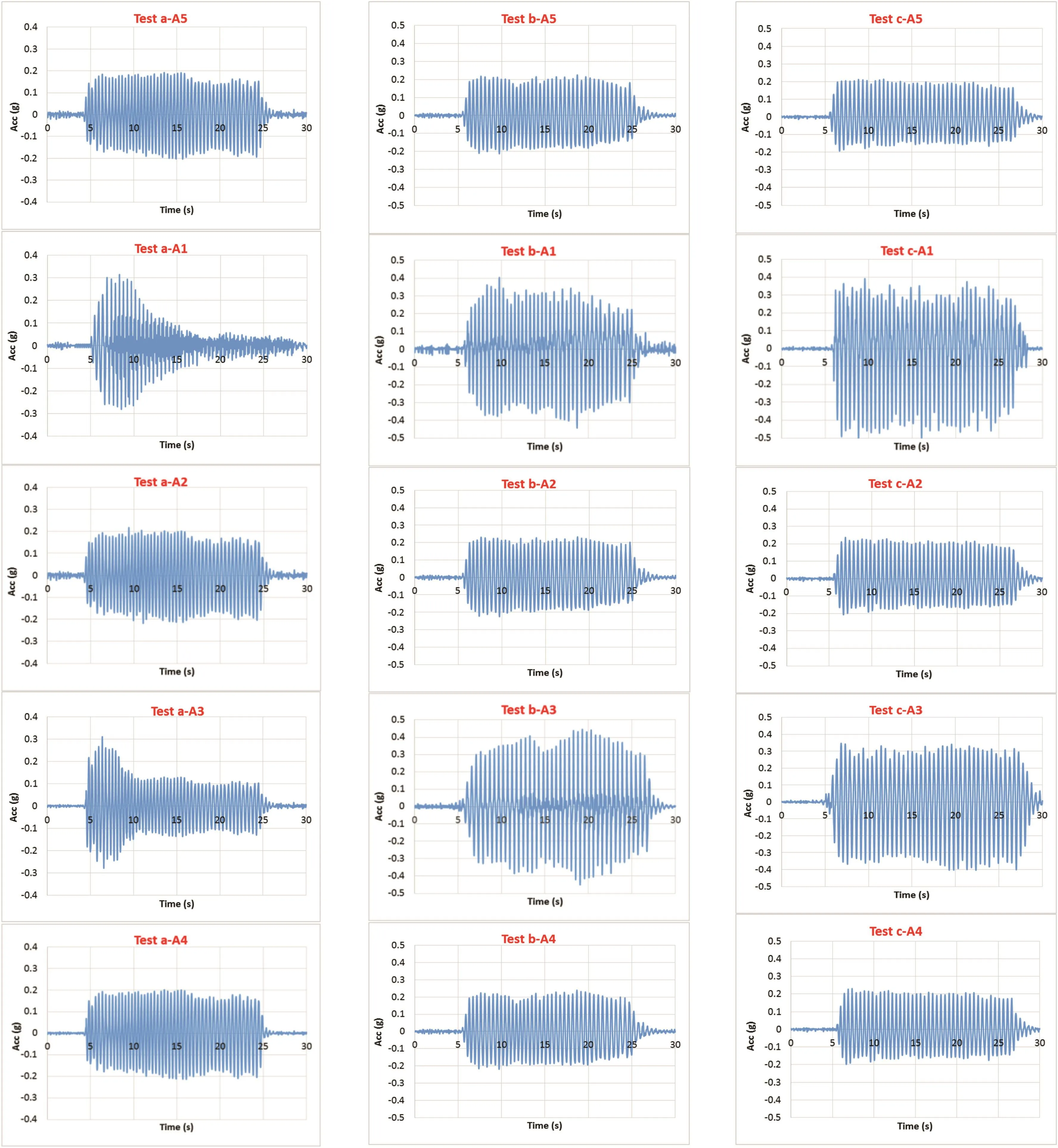
Fig.6.Time histories of tests a,b and c(Acc represents the acceleration).
A loose sand has a tendency to compress when a load is applied.Accordingly,if these soils are saturated,the first effect of the seismic loadings on them in the undrained condition is the rapid generation of excess pore water pressure.The dissipation rate of the excess pore water pressure generated during seismic loading depends on factors like soil physical properties(such as permeability)and also the length of drainage path.It can be observed that the increases in number and diameter of drainage columns reduce the generated pore water pressure.Gravel drainage columns are better than rubber drainage columns on moderate accelerations(tests a,b,c and f).
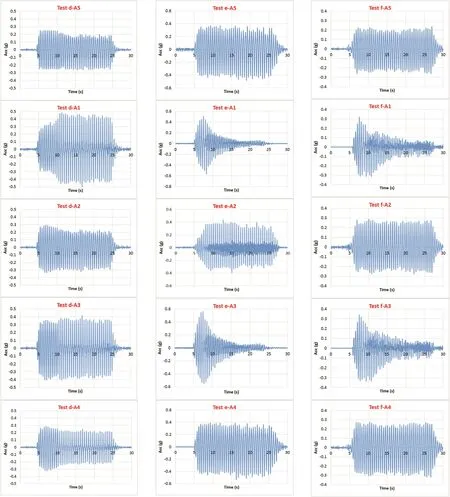
Fig.7.Time histories of tests d,e and f.
Also,it is obvious that the increases in diameter and number of drains lead to reduction of the length of drainage path and prevention of soil softening and liquefaction.Furthermore,at relative density of 30%,rubber drainage columns have a better effect on reducing generated pore water pressure compared to gravel drainage columns(test d).In fact,soil compaction has a better performance in reducing excess pore water pressure in comparison to the increased number of drains.Although both samples(test e)are liquefied at high acceleration,generated excess pore water pressure of the sample reinforced with rubber drainage column is relatively less than that of the sample reinforced with gravel drainage column.This sudden increase is due to the lack of drainage opportunity of generated pore water pressure at high acceleration.Therefore,it leads to the occurrence of liquefaction in both samples.Generally,compaction is able to increase liquefaction resistance more than gravel drains.
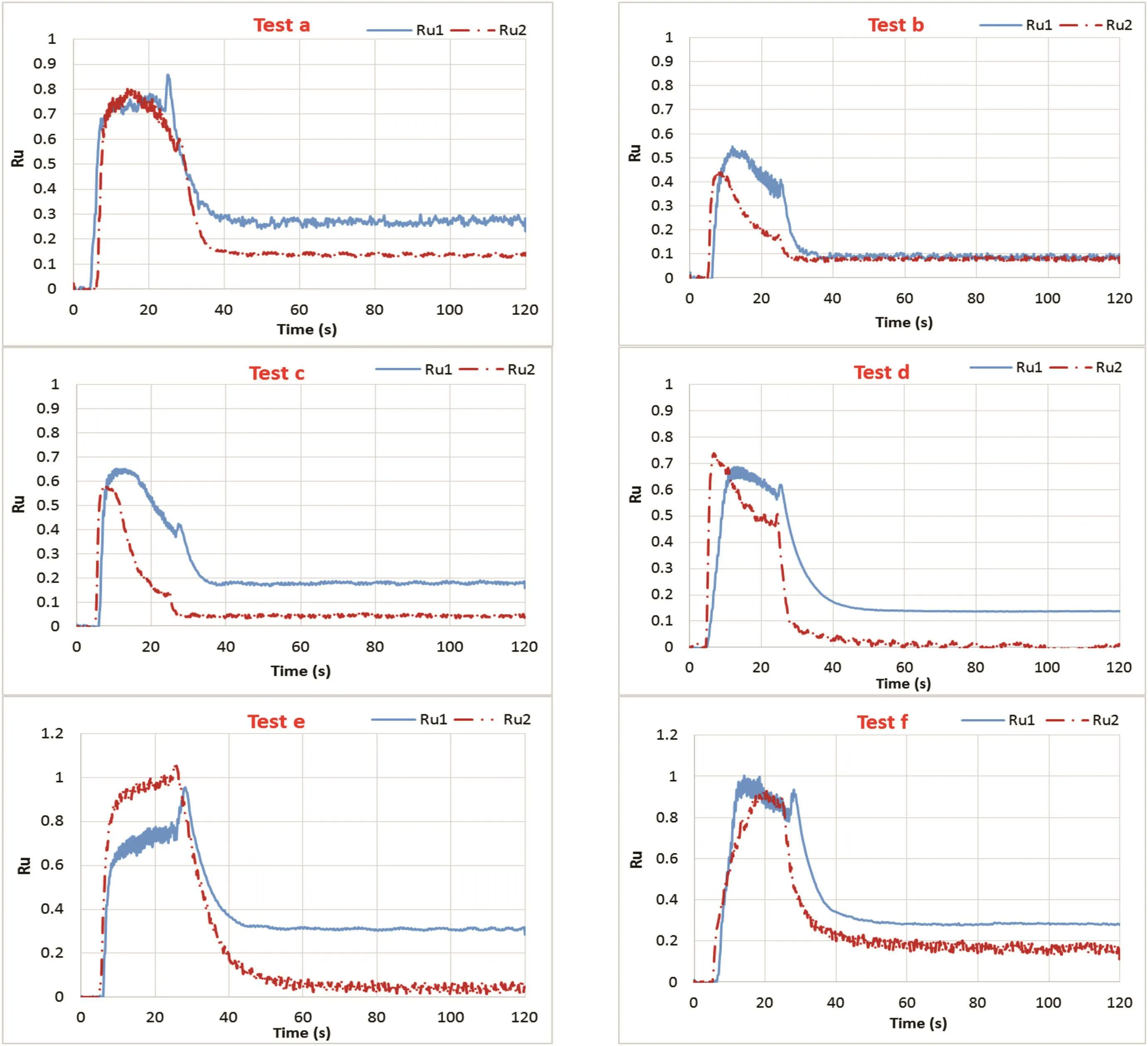
Fig.8.Time histories of excess pore water pressure ratio.
The excess pore water pressure ratio data(Fig.8)indicate that at a specific depth(z=30 cm),there is a point on time axis after which the excess pore pressure starts to dissipate at a much higher rate,proving their effectiveness in non-dynamic cases.This can be the initial period,where vertical dissipation has no chance to get held on the soil at the corresponding depth,and only radial drainage is experienced at that depth.Moreover,after shaking,gravel drainage columns drain quicker than rubber drainage columns,and the excess pore pressures remain larger in the models improved with rubber drain.The dissipation rates of excess pore water pressures generated in models reinforced with gravel drain are remarkable.Such a phenomenon was also observed by Sadrekarimi and Ghalandarzadeh(2005).
The reason for the good performance of gravel drains in reducing generation of excess pore pressure and increasing liquefaction resistance at moderate input acceleration is the high permeability of the gravel,as compared with tire chips.
Fig.9 shows the maximum excess pore water pressure ratio for all samples improved with rubber and gravel drainage columns.It shows that in the samples of tests e and f,the liquefaction has completely occurred and Ruis greater than 0.95(Matsumura et al.,2015).When the relative density of the soil and the number of drainage columns increase,the liquefaction is gradually controlled and,in test d(Dr=30%),the liquefaction is prevented very well.The relative density of sand rises,so does its liquefaction resistance(Noorzad and Amini,2014).
3.3.Time history of settlement
Settlement is one of the consequences of liquefaction.Rearrangement and densification of saturated sand during the shaking and dissipation of generated excess pore water pressure after the shaking can lead to excessive settlement of ground surface due to the post-liquefaction consolidation procedure.Fig.10 depicts the time histories of vertical displacement measured by LVDTs.
Fig.11 demonstrates the maximum settlement generated in all models.As shown in this figure,the samples of test e experienced the largest vertical displacement among all the models,followed by test f.The effects of rearrangement and densification of saturated sand during high shaking are impressive.However,test d with relative density of 30%has the lowest settlement due to the low volume of void among soil particles.
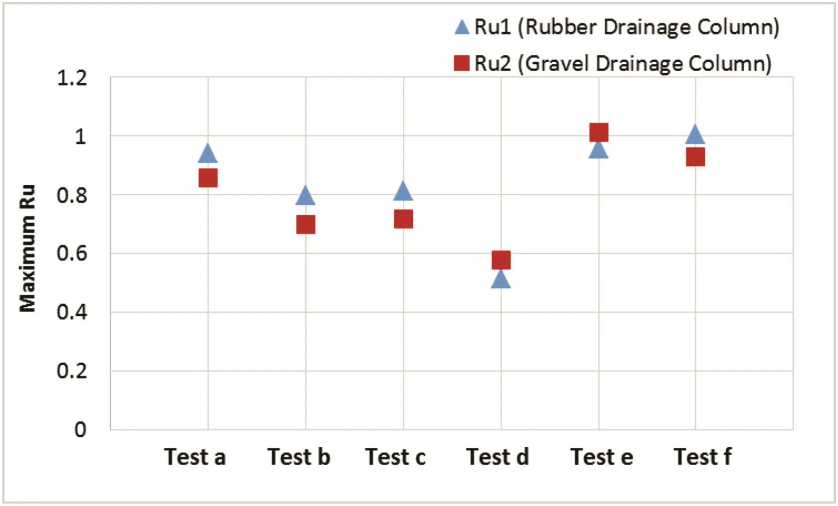
Fig.9.Maximum excess pore water pressure ratio generated in all models.
Fig.12 shows the changes of maximum excess pore water pressure ratio(Eq.(3))and maximum settlement(Eq.(4))of samples compared to the base test samples(test a).According to the core parameters method,only one parameter is changed in each test and the other parameters are constant,the effect of each parameter on test a is presented.Positive(+)and negative(-)signs respectively indicate the increase and decrease of liquefaction potential compared to base test(test a).The results show that the combination of compaction and execution of drainage column(test d)has better effect on the reduction of excess pore water pressure and settlement of saturated sandy soil in comparison to other tests.

where ΔRui,ΔLi,Ruiand LVDTidenote the changes of maximum excess pore water pressure ratio and maximum settlement,excess pore pressure ratio at position i and vertical displacement at position i,respectively.
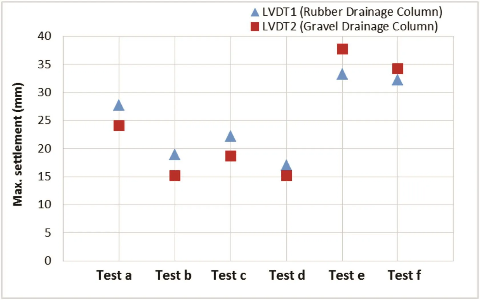
Fig.11.Maximum settlement generated in all models.
The influences of the high density on reducing Ruin the samples improved with rubber and gravel drains are 45%and 33%,respectively,as well as the settlements of both samples decreased to 38%.The settlement was reduced by 32%and 37%when four rubber and gravel drains were installed.Reducing the drain diameter increased the settlement of samples improved with rubber and gravel drains up to 16%and 42%and Ruvalues increased up to 7%and 9%,respectively.The effect of the high shaking on the increase in the settlement of model improved with gravel drain is dramatically high(approximately 57%)while this increase in the model improved with rubber drain is 20%.
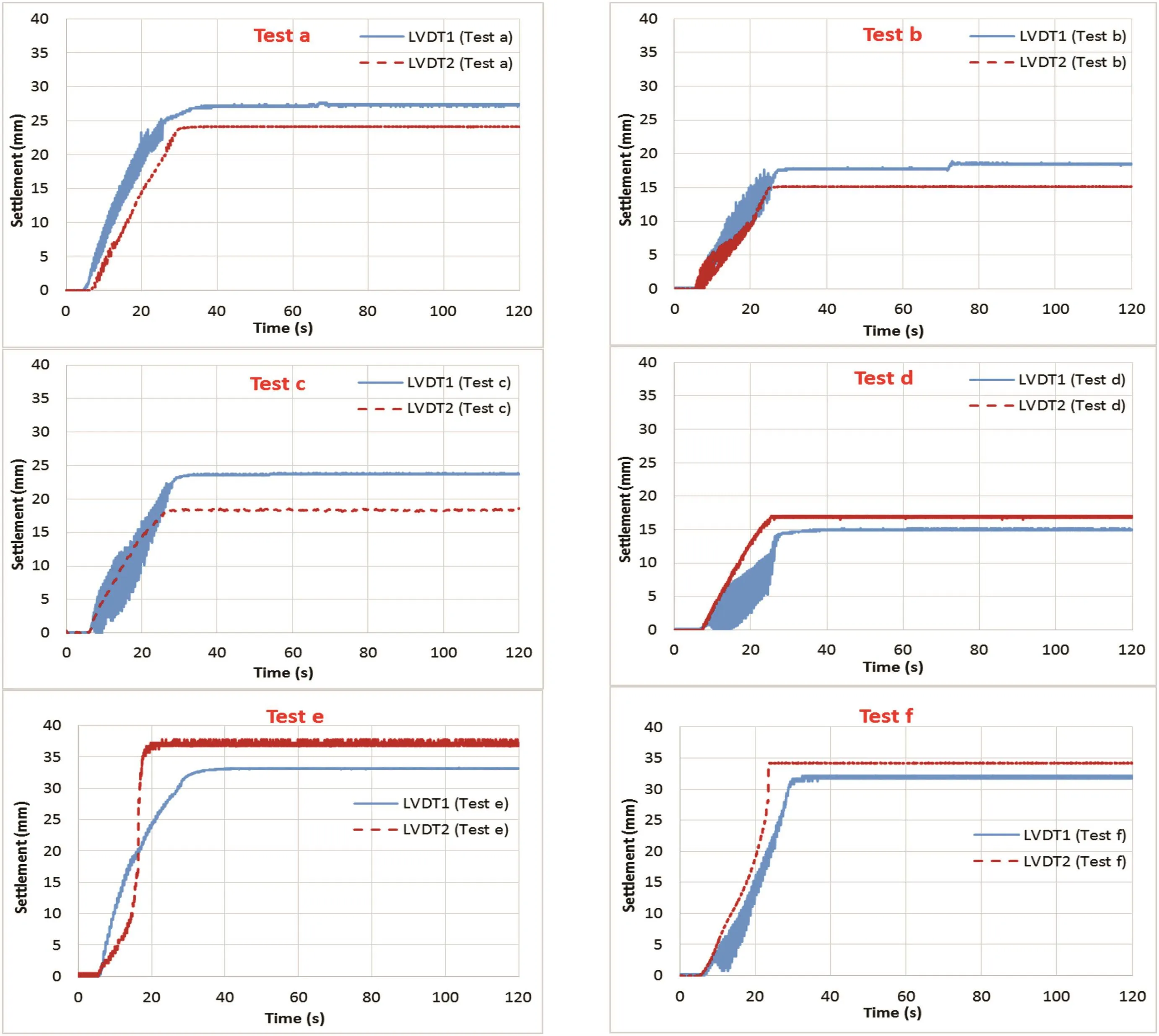
Fig.10.Time histories of settlement.
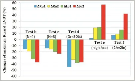
Fig.12.Changes of maximum Ruand LVDT.
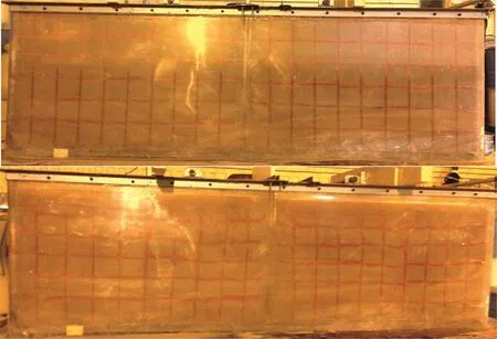
Fig.13.Model test a before(upper)and after(lower)shaking(left:model improved with gravel drain;right:model improved with rubber drain).
3.4.Model deformations
In order to understand the deformations induced by liquefaction during shaking,a squared net of colored sand was constructed on the front face of the shaking container for both models.Fig.13 illustrates the model deformations of test a after shaking.As shown in this figure,both models experienced a roughly similar magnitude of deformation.
4.Conclusions
In this study,shaking table tests were performed to evaluate the effectiveness of rubber columns applied to loose sandy deposits,as a liquefaction countermeasure.In addition,the performances of rubber and gravel columns in order to examine the effects of the input motion,the number and diameter of drains and the densification on mitigation of liquefaction potential of soil have been investigated.The results of the tests are drawn as follows:
(1)Increases in the number and diameter of gravel and rubber drainage columns in sandy soils reduce the excess pore water pressure and increase the liquefaction resistance.
(2)Gravel drainage columns have better performance than the rubber drainage columns at moderate accelerations.
(3)At high accelerations,by liquefaction in both samples,the improved sample with rubber drainage column has less excess pore water pressure and settlement compared to the improved sample with gravel drainage column.
(4)At high relative density,the improved sample with rubber drainage columns has less excess pore water pressure and settlement compared to the improved sample with gravel drainage column.
(5)The drainage rate of gravel drains is higher than the rubber drains after shaking.
(6)Generally,soil compaction plays a key role in reducing liquefaction potential compared to the increasing number of drains.
Conflicts of interest
We wish to confirm that there are no known conflicts of interest associated with this publication and there has been no significant financial support for this work that could have influenced its outcome.
 Journal of Rock Mechanics and Geotechnical Engineering2018年5期
- Journal of Rock Mechanics and Geotechnical Engineering的其它文章
- Pullout behavior of polymeric strip in compacted dry granular soil under cyclic tensile load conditions
- Blast-induced rock damage control in Fangchenggang nuclear power station,China
- Bearing behavior and failure mechanism of squeezed branch piles
- Experimental evaluation of mechanically stabilized earth walls with recycled crumb rubbers
- Dynamic properties and liquefaction behaviour of cohesive soil in northeast India under staged cyclic loading
- Saturated anisotropic hydraulic conductivity of a compacted lateritic soil
