Analysis of RF Feedback Chain Isolation in Wireless Co-Time Co-Frequency Full Duplex
Juan Zhou | Ying Shen* | Ya-Juan Xue | Li Li
Abstract—By employing a radio frequency (RF) feedback chain, the self-interference can be canceled efficiently in co-time co-frequency full duplex (CCFD). However, the evitable signal crosstalk which is caused by the imperfect RF feedback chain isolation usually damages the self-interference cancelation (SIC) performance. To deal with this problem, firstly, we analyze the impact of RF feedback chain isolation on SIC performance. Then a digital preprocessing scheme with RF feedback chain is proposed in the multiple-antenna CCFD architecture. Using both analytical and experimental methods, we find that the proposed scheme achieves a better performance on SIC.
1. Introduction
Co-time co-frequency full duplex (CCFD) operation has emerged as an attractive solution for increasing the spectrum efficiency of wireless communication systems[1]-[6]. However, when a wireless terminal transmits and receives at the same time in a same frequency band, the self-interference problem arises and becomes one of the biggest practical impediments to CCFD operation[7]-[11]. To suppress the self-interference efficiently, the RF feedback chain was employed in the CCFD architecture in [12] and [13]. However, the imperfect RF feedback chain isolation,as an important technical specification in practical project, is usually neglected for the analysis of the RF feedback chain.
For practical CCFD project, it has been experimentally demonstrated that the self-interference cancelation (SIC)performance is influenced by the RF chain isolation. The reason is that the RF signal leaks owing to the imperfect RF chain isolation. In this paper, we focus on the impact of the RF chain isolation on SIC performance. A mathematical analysis will be given first, and then a new scheme will be presented, aiming at reducing the adverse impact on SIC.
In the proposed scheme, firstly, the RF leakage signal is collected and analyzed by using the feedback RF chain. And then, the parameters for the reconstruction of the leakage signal are optimally estimated. With the optimal parameters, the CCFD receiver can subtract the real-time leaked RF signal from the required signal, so as to cancel the impact of the RF leakage signal on SIC performance.
The system model and the impact of the RF chain isolation on SIC are explained in Section 2. In Section 3, the proposed scheme for reducing the RF chain isolation impact is proposed. Numerical results are presented in Section 4. Conclusions are drawn in Section 5.
2. System Model and RF Chain Isolation Impact
As depicted in Fig. 1, we consider a multipleantenna CCFD architecture with RF feedback chain.For the analysis convenience, the architecture includes two transmit antennas (Tx), two receive antennas (Rx),and two corresponding feedback (Fb) chains. Certainly,similar analysis can be applied to more antennas.
As shown in Fig. 1, the expected signals are x1and x2, respectively. Considering the RF leakage signal, the signals to be transmitted are x1+γ1x2and x2+γ2x1, where γ1denotes the leakage factor from Tx2chain to Tx1chain, and γ2is the leakage factor from Tx1chain to Tx2chain. Similarly, the feedback signals are z1=x1+β1x2and z2=x2+β2x1, where β1denotes the leakage factor from Tx2chain to Fb1chain, and β2is the leakage factor from Tx1chain to Fb2chain.
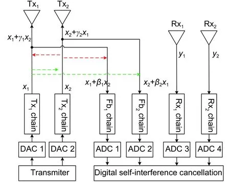
Fig. 1. CCFD architecture with feedback chains. Tx, Fb,and Rx represent transmitting, feedback, and receiving,respectively.
With hi,jdenoting the channel condition from the transmitting antenna Txito the receiving antenna Rxj, the signals at the receiving antennas can be represented as

and

For a better description of the RF leakage signal, the leakage signal power is measured with a spectrum analyzer, and the measured result is shown in Fig. 2. The transmitting antenna Tx2works while transmitting antenna Tx1is silent. The transmitted signal power is 30 dBm with a bandwidth of 20 MHz. The leakage signal in the feedback chain (Fb2chain) is measured as much as -7 dBm. The specific RF leakage signal impact on SIC performance is analyzed as follows.
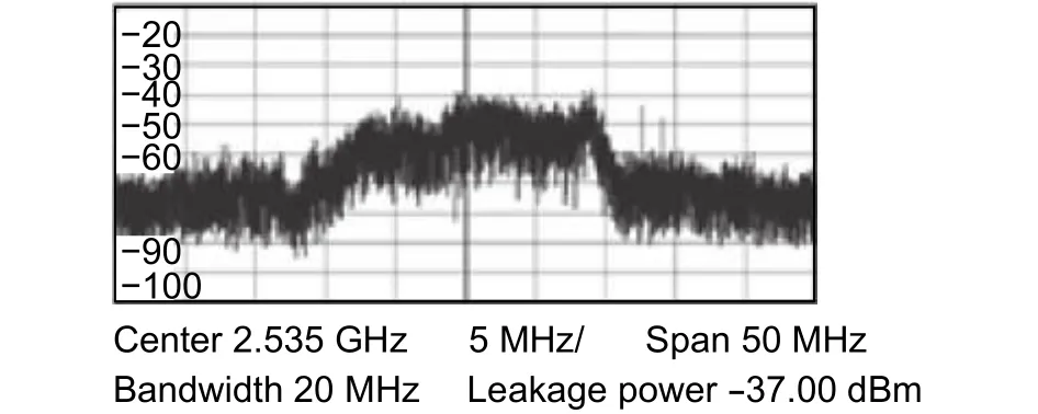
Fig. 2. Power spectrum of the RF leakage signal.
For the SIC in CCFD, the channel information is usually determined as follows. At time t1, the pilot signal x1,pis transmitting at Tx1while Tx2is silent. The corresponding feedback signal and the received signal are z1,p=x1,pand y1,p=h11x1,p+h21γ2x1,p, respectively. Then the estimated channel conditioncan be expressed as

At time t2, the pilot signal x2,pis transmitting at Tx2while Tx1is silent. The estimated channel conditioncan be similarly analyzed as


The practical self-interference signal is s1=h11z1+h21z2. After SIC, the residual self-interference at the Rx1chain can be calculated by

The expected residual self-interference signal at the Rx1chain is, which is true only under the conditions β1=0 and β2=0. γ1and γ2do not affect the SIC performance. Similar analysis can be applied in the residual selfinterference signal at the Rx2chain. However, these conditions are too critical to realize. To deal with this problem,a digital pre-processing scheme is provided in the following section.
3. Digital Pre-Processing Scheme for Reducing RF Chain Isolation Impact
The proposed digital pre-processing scheme is shown in Fig. 3, which is implemented before the CCFD transceiver starts to work. The procedure of the proposed scheme is briefly depicted as follows:
a) The parameters of RF leakage signal owing to imperfect RF chain isolation are tuned and determined,including time, amplitude, and phase.
b) Based on the determined parameters, the RF leakage signal is estimated and subtracted from the required signal for reducing the RF chain isolation impact.
c) The residual signal power after subtraction is calculated to determine whether the estimated RF leakage signal is well approximated with the practical RF leakage signal.
d) If not, go on with step a). Others, the proposed scheme is complemented, and the CCFD transceiver starts to work with the determined RF leakage parameters.
As shown in Fig. 3, the signal g1is transmitted in the Tx2chain, and the RF signal is leaked to the Tx1chain as g4. To eliminate the RF leakage signal impact, the estimated RF leakage signal g2is subtracted from g4to obtain the feedback signal g0.
Based on the baseband transmitting signal g1(k) and the estimated parameters, the RF leakage signal estimated in the digital processing unit iswhich can be further written in the RF domain as

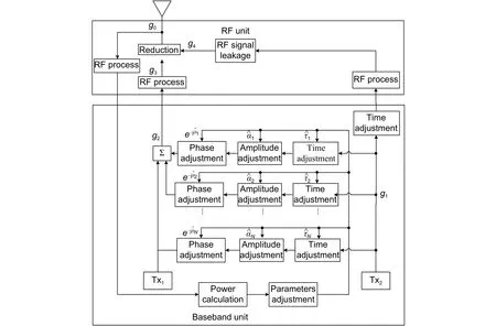
Fig. 3. Proposed digital pre-process scheme.

Similarly, the practical RF leakage signal g4(t) is expressed as


Similarly, the real RF leakage signal g4(t) can be given by

As described in the proposed scheme, the estimationof the time delay, amplitude, and phase offsets on each path is the key problem to be solved. Firstly,is determined by the time difference between the signals g3and g4.Then the timedelay of each path can be calculated by. Later in the paper, we will focus on the estimation of amplitude and phase offsets.
The residual RF leakage signal power can be expressed as

For analysis convenience, let


which is shown to be convex on D. (Refer to Appendix A.)
The above analysis focuses on the case where Tx2is transmitting while Tx1is silent. Then the same process is applied in the other case where Tx1is transmitting while Tx2is silent. Finally, with all the parameters achieved, the digital pre-processing scheme is completed for the CCFD framework as shown in Fig. 3.
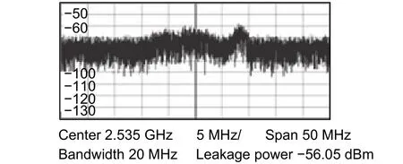
Fig. 4. Power spectrum of the RF leakage signal.
By employing the proposed scheme, the leakage signal shown in Fig. 2 can be effectively reduced from-37.00 dBm to -56.05 dBm, which is shown in Fig. 4.
4. Numerical Results
To confirm the theoretical analysis, the simulation platform is developed as follows 3rd generation partnership project long term evolution (3GPP LTE) protocol with 20 MHz bandwidth is applied in the CCFD system and the recursive least square (RLS) algorithm is employed as the digital self-interference cancelation method[14],[15]. The interference to noise ratio (INR) is set to be 60 dB, and correspondingly the expected SIC performance is 60 dB with the residual RF leakage signal canceled perfectly.
The practical RF leakage signal is assumed to be comprised of three paths. The amplitudes, phases, time delays for these paths are respectively defined as follows, the amplitudes are α1=1, α2=0.9, and α3=1.1,the phases are φ1=0, φ2=0.5, and φ3=1, and the time delays are τ1=0, τ2=3Δ, τ3=6Δ . Here Δ=1/30.72×106is the chip time based on LTE protocol.

Fig. 5. CCFD SIC performance comparison in different RF signal leakage ratios.
Fig. 5 depicts the SIC performance in different RF signal leakage ratios. RF signal leakage ratio is the ratio between the signal power to be transmitted and the signal power leaked. From Fig. 5, it is found that the SIC performance with the proposed scheme is close to the expected value 60 dB, which means that the RF chain isolation impact can be canceled with the proposed scheme. However, without the proposed scheme, the SIC performance is apparently damaged with increasing RF signal leakage ratio. This is because the residual RF leakage signal is the main part of the residual interference signal.
5. Conclusions
In this paper, it is analyzed that the imperfect RF chain isolation damages the SIC performance in CCFD. Then a digital preprocessing scheme is proposed for eliminating the RF chain isolation impact. With both theoretical analysis and simulation demonstration, it is shown that the proposed scheme achieves a better performance in the CCFD with the RF feedback chain.
Appendix
Based on [17], the residual RF leakage signal power can be expressed as


Since R is an autocorrelation and positive semidefinite matrix,is convex on[17]. Heredenotes the amplitude and phase parameters depending on [9], which means thatis convex on the amplitude and phase parameters needed in the proposed scheme.
 Journal of Electronic Science and Technology2018年3期
- Journal of Electronic Science and Technology的其它文章
- Review on Fault-Tolerant NoC Designs
- Adaptive Algorithm for Accelerating Direct Isosurface Rendering on GPU
- Enhancing Design of Visual-Servo Delayed System
- Review of Methods of Image Segmentation Based on Quantum Mechanics
- Spatial Channel Sounding Based on Bistatic Synthetic Aperture Radar Principles
- Blood Flow Simulation in the Femoral Artery
