Review on Fault-Tolerant NoC Designs
Jun-Shi Wang|Le-Tian Huang*
Abstract—By benefiting from the development of the semiconductor technology, many-core system-on-chips (SoCs)have been widely used in electronic devices. Network-on-chips (NoCs) can address the massive stress of on-chip communications due to the advantages of high bandwidth, low latency, and good flexibility. Since deep sub-micron era, the reliability has become a critical constraint for integrated circuits. To provide correct data transmission, faulttolerant NoCs have been researched widely in last decades, and many valuable designs have been proposed. This work introduces and summarizes the state-of-the-art technologies for fault diagnosis and fault recovery in faulttolerant NoCs. Moreover, this work makes prospects for the future's research.
1. Introduction
As the technology scaling, the integrated circuits (ICs) achieve the higher integration density than ever before.Many more components can be manufactured within a single chip to enhance the function of system-on-chips(SoCs). Thus, many-core SoCs have been used widely in high-performance computation, embedded systems, and other fields. For example, Intel Xeon processors[1], IBM Z processors[2], Oracle SPARC M7 processors[3], NVIDIA Tesla processors[4], and Tilera TILE 64 processors[5]are typical commercial many-core SoCs.
Because a single chip integrates many more intellectual properties (IPs) than ever before, such as processor cores and accelerator units, computation resources are not the bottleneck of the system performance anymore.Instead, many powerful IPs raise the stress on on-chip communications structure significantly. The design of SoC moves from the computation-center design to the communication-center design[6].
Traditional bus-based communications architecture cannot address the requirement of high bandwidth,flexibility, and reliability for on-chip communications. Firstly, one bus can only be driven by one master component exclusively. As shown in Fig. 1 (a), no parallel communication is supported. Then, the bandwidth of existing devices drops when new devices are added to the bus because the bandwidth of a bus is not scalable. Moreover, as the extension of the physical length, the transmission delay of one bus increases so that the working frequency reduces. At last, buses do not provide redundancy resources and become the critical point of the entire system.

Fig. 1. Bus and network-on-chip: (a) bus and (b) network-on-chip.
The network communications architecture, known as the network-on-chip (NoC), can support parallel communications, reduce the physical length of wires, and scale the bandwidth. NoCs can support multiple parallel communications at the same time. As shown in Fig. 1 (b), three communications streams are delivered at the same time. When new devices added to NoCs, NoCs can increase the bandwidth by extending the network size.Meanwhile, the length of wires is limited by the distance between routers and does not increase as the increase of network scale. Finally, NoCs provide comprehensive and rich redundancy resources so that fault-tolerant designs can be implied. Therefore, NoCs are widely used in many-cores systems to address the on-chip communications stress.
During manufacture and utilization, ICs cannot always be ideal. Physical failures change the logic value of signals and lead to misbehaviors further. As the continually improved technology and integrated density, the circuit fault becomes more and more prominent and has already been one of the critical challenges for ICs. As reported by National Aeronautics and Space Administration (NASA)[7], the fault probability during lifetime increases and lifetime also reduces as the improvement of technology. As shown in Fig. 2, the fault rate reduces in the early age of life due to the manufacturing defects, keeps constant during the most time of life due to the random faults, and increases in the later stage of life due to aging and wear-out. The technology improvement increases the constant fault probability and accelerates aging.

Fig. 2. Fault rate as the technology improves.
If the faults happen in the NoCs, IP cores cannot get necessary data, or the received data is not correct. If IP cores cannot get essential data in time, the operation of IP cores is blocked. If the data accepted by IP cores is not correct, the processing of IP cores would be faulty as well, for example, error results, error instructions, and error jump. At last, the faults in NoCs reduce the efficiency of many-core systems. Therefore, it is necessary to guarantee the reliability of NoCs through effective fault-tolerant designs so that the many-core systems can work correctly.
Fault-tolerant NoCs are an important issue in the field of NoCs[8]-[11]. Fault-tolerant NoCs should improve the reliability of NoCs as far as possible. On the other hand, fault-tolerant NoCs should reduce the area overhead,power consumption, and performance loss introduced by fault-tolerant designs. Hence, fault-tolerant designs for NoCs can be described by two optimization problems:
1) Give out a design to achieve the best reliability addressing constraints of area, power, and/or performance.
2) Give out a design to minimize the area overhead, power consumption, and/or performance loss addressing the constraints of reliability[11].
Before 2010, researchers focused on the first-class optimization problems and proposed many fault diagnosis and fault recovery methods[12]. Currently, researchers pay more and more attention to the second-class optimization problems. It is worth to review and summarize published work to provide references for further research.
The organization of the rest is as follow: Section 2 introduces the conceptions and typical design of NoCs.Section 3 describes the fault models in the physical layer, the circuit layer, and the behavior layer. Section 4 and Section 5 review the state-of-the-art fault-tolerant design. Section 4 introduces the fault diagnosis methods including test methods and test strategies. Section 5 summarizes fault recovery methods classified by network layers and redundancy resources. The further research prospects are discussed in the last section.
2. NoC
Similar to the Internet, NoCs can also be divided into five layers: The physical layer, data-link layer, network layer, transport layer, and application layer (Fig. 3). The studies of NoCs focus on the middle three layers. The data-link layer transfers data between routers. The network layer guarantees the data delivery between the source router and destination router. The transport layer gets data from the source IP core and delivers the data to destination IP core correctly. The layered architecture of NoCs can simplify the design and analysis, but the boundaries between layers are broken at the final design and layout. Therefore, the research of NoCs tends to optimize the designs by cross-layer designs.
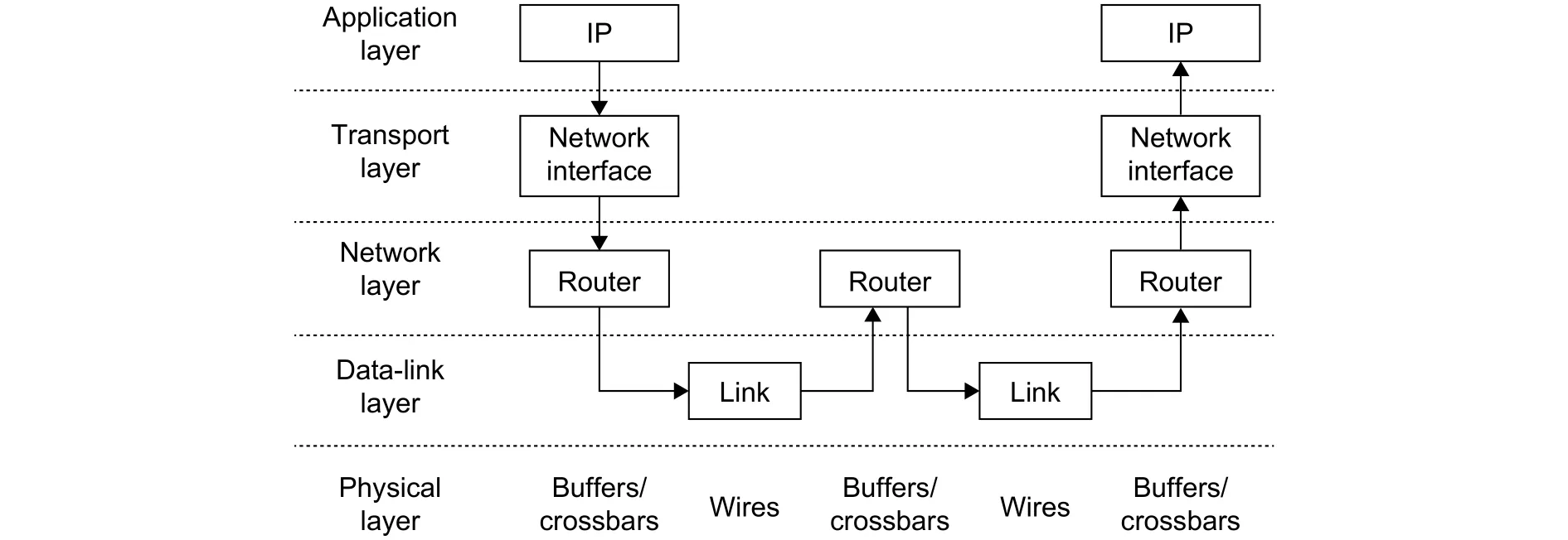
Fig. 3. Layer model of NoCs.
Routers and links are connected according to certain rules, which is called topology. Because NoCs are built by hardware, the topology of NoCs is determined during the lifetime of chips. The mesh topology is the most commonly used topology in research. Routers are placed in a matrix as shown in Fig. 4. An m×n mesh network locates routers into a matrix with m rows and n columns. The mesh topology can support more parallel communications paths and provide a higher communications bandwidth related to other topologies. There is no apparent critical router or link in the mesh topology so that the mesh topology has better scalability than other topologies. Meanwhile, the mesh topology provides rich redundancy resources and achieve better reliability.
A router and IP cores connected to this router are called "tile" in many-core systems. Fig. 5 shows an example architecture of one tile. Within the tile, IP cores connect the router through the network interface (NI). IP cores generate data to deliver. NI packages data into packets and sends data to the source router. Routers and links forward and deliver data packets to the destination router. The destination router forwards packets to the destination NI. The destination NI unpackages the data packets and provides data to IP cores.
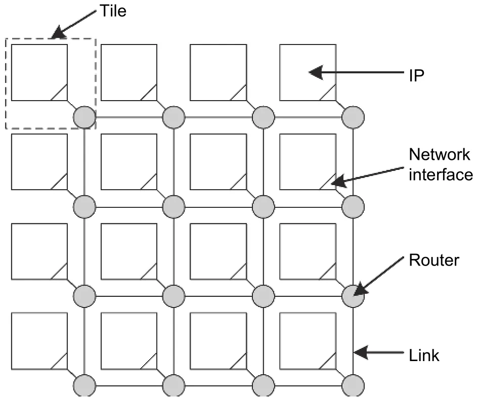
Fig. 4. Mesh topology NoCs.
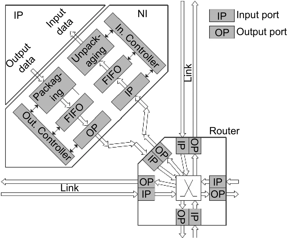
Fig. 5. Tile architecture for NoC based many-core systems.
Different from the Internet, the links between routers are parallel. The data transferred by parallel wires in one cycle is defined as the flow control unit (flit). One flit contains 32 bits, 64 bits, or 128 bits. One data packet includes several flits. The first flit is called the head flit, which holds the routing information, e.g., the source address,destination address, and packet ID. The last flit is called the tail flit while other flits are called body flits. The body flits and tail flit deliver data. The tail flit can be used to hold correction check information as well. Fig. 6 shows the architecture of one data packet.
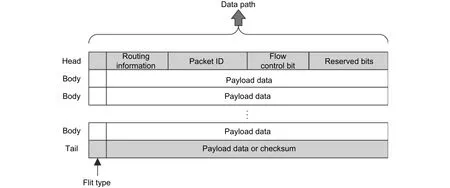
Fig. 6. Data packets in NoCs.
Routers are consist of the input ports, output ports,and crossbar. Input ports and output ports connect to other routers through links or connect to NIs. The ports connected with NI are called local ports. Fig. 7 shows a typical router architecture. The circuits in one router can be divided into the data path and control path. The data path contains the input buffers, crossbar, and output registers. The control path includes the buffer control logic, pipeline control logic, arbiters, and so on.
NoCs usually imply the wormhole switching technology. Different from the store-and-forward,wormhole switching does not require the routers to hold the entire packets. The router determines the forward direction according to the routing information in the head flit and assigns the correct hardware channel. The body and tail flits are sent through the assigned hardware channels. The hardware channels are released after the tail flit. Therefore, the flits belonging to one packet can locate in different routers, as shown in Fig. 8. The flits of packet B are stored in Router 1 and Router 2. Routers for wormhole switching do not need a large number of buffers so that the area overhead reduces. Meanwhile, wormhole switching accelerates the pipeline and reduces the delay for packets passing through one router because it is not necessary to wait for the tail flit.
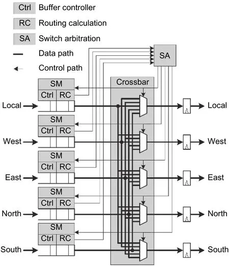
Fig. 7. Typical router architecture.
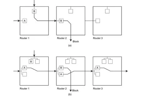
Fig. 8. Wormhole switching and virtual channels: (a) without virtual channel, packet A is blocked by packet B in Router 1 and (b) with virtual channel, packet A and packet B deliver through Router 1 and Router 2 simultaneously.
If there is no free space in the next stage router, the flit should be blocked in the current router. In NoCs, flow control methods are designed to control the movement of flits. The credit-based flow control method is the most common for NoCs with buffers. The credit-based flow control method can determine whether the next stage router has enough space to accept this flit because the next stage router feedbacks the number of free space in buffers(credit) to the current router. If there are free spaces, the flit is sent. Otherwise, the flit is blocked. Credit information can be used to not only control the flit delivery but also optimize the traffic load and avoid congestion.
Buffered router architectures may lead to congestion. One reason for traffic congestion is that flits are blocked because the next stage router does not have spaces to accept new flits. The other reason for traffic congestion is that packets are blocked because packets do not get grants from arbiters during the resource competition. Flits are blocked in the router until there are enough spaces for delivery or arbiters give grants. Under the wormhole switching technology, congestion can diffuse to the entire network because packets are located in different routers.As shown in Fig. 8 (a), Router 1 and Router 2 both have congestion due to the blocking of packet B. Packet B occupies the channels in Router 1 and Router 2, so that packet A in Router 1 is also blocked because of no grant from the arbiter.
Virtual channels are very useful to reduce the impact of congestion on network performance. The input buffers are divided into several parts, and each part has the exclusive routing calculation and flow-control logic. When one virtual channel is blocked, the other virtual channels belonging to the same port can still deliver packets. As shown in Fig. 8 (b), packet A can still deliver through Routers 1, 2, and 3 through another virtual channel although packet B is blocked. Virtual channels reduce the packets impacted by traffic congestion and reduce the average network latency further.
Flits queue at the input buffer after entering the router. Then, the flits deliver to the output register through the crossbar. Finally, flits leave the router from the output register. A flit needs five stages to deliver through a router,which is usually called the five-stage pipeline for NoC routers. As shown in Fig. 9, the five-stage pipeline includes the routing calculation (RC), virtual channel arbitration (VA), switching arbitration (SA), switch traversal (ST), and link traversal (LT).
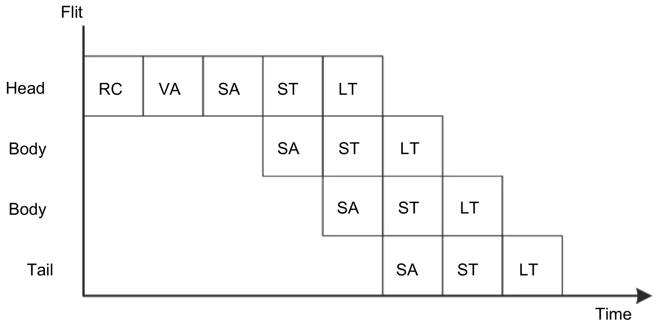
Fig. 9. Five-stage pipeline for NoC routers.
1) RC determines the forwarding direction according to the routing information within the head flits.Sometimes, the selected virtual channel in the next stage is determined at the same time.
2) VA determines which packet can be delivered to the selected direction when multiple packets request the same input buffer in the same router. Then, the packets are assigned to the input buffer by VA.
3) SA determines which flit can deliver through the requested output port if multiple flits request the same output port.
4) ST forwards flits from the input buffer to the output register through the crossbar.
5) LT sends the flits to the next stage router through links.
3. Fault Modeling
Faults can be described in three layers: Physical failures, logic errors, and network misbehaviors as shown in Fig. 10. Physical failures describe the voltage and current fluctuations introduced by crosstalk, aging, and other reasons. Logic errors describe the changes in logic values due to the voltage fluctuation. Network misbehaviors show the misbehaviors of routers and packets caused by the error signals. Thus, logic errors are the abstraction of the physical failures, while network misbehaviors are the further abstraction of logic errors. The physical failures and logic errors suffered by NoCs are common for ICs in the deep submicron era. However, network misbehaviors are unique for NoCs, which are not only related to circuits but also the network theory.
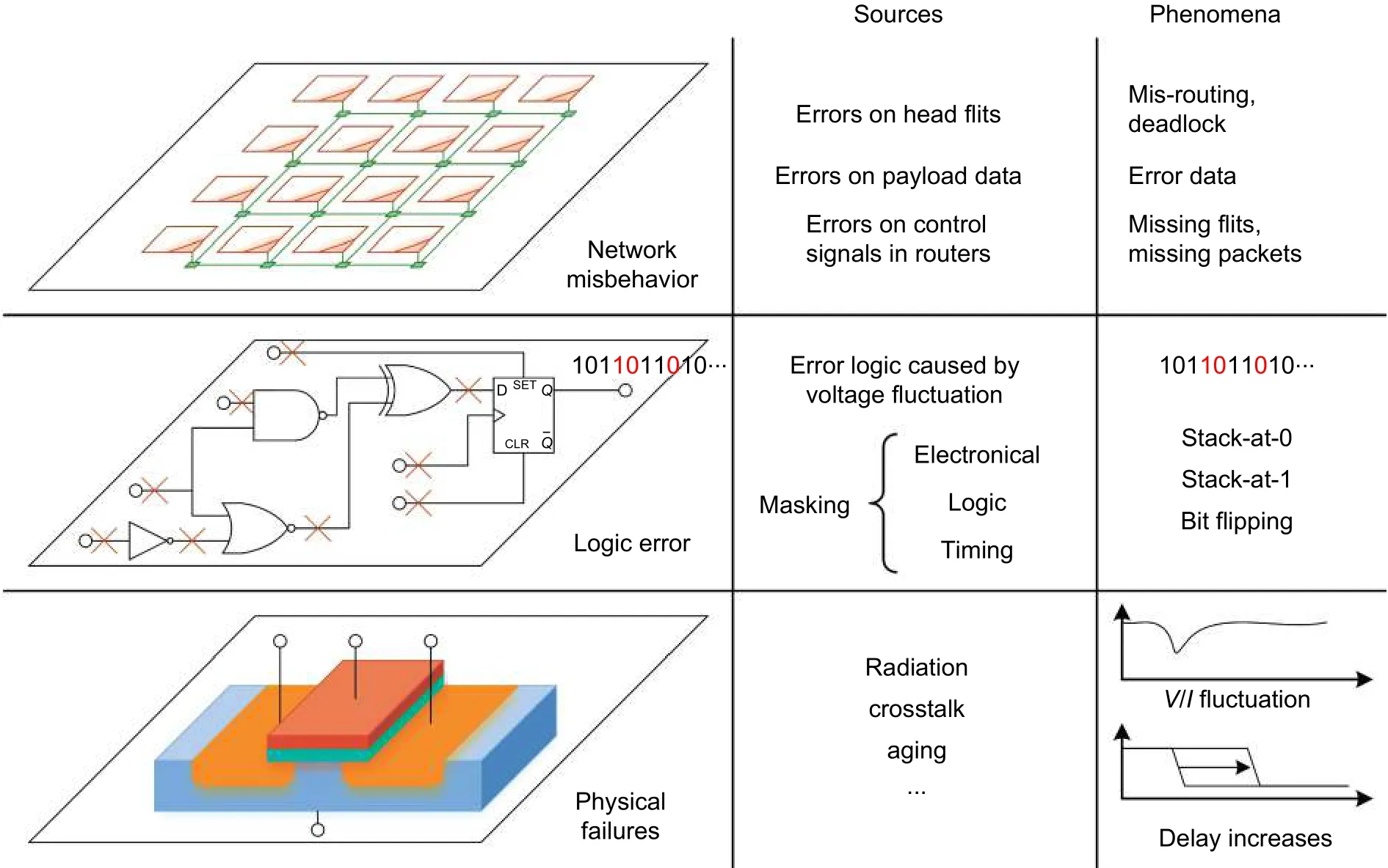
Fig. 10. Sources and phenomena of physical failures, logic errors, and network misbehaviors.
3.1. Physical Failure
Major causes of physical failures include the radiation, crosstalk, and aging.A. Radiation
Three radiation mechanisms have been discovered: Alpha particles emitted by trace uranium and thorium impurities in packaging materials; high-energy neutrons from cosmic radiation; low-energy cosmic neutron interactions with the isotope boron-10 in IC materials[13]. When particles attack ICs, the electrons nearby one PN junction will be reordered which leads to glitches in voltage and current. Obviously, the radiation mainly influences gates, registers, and memories but not wires. As the reduction of features size, the scale of a single PN junction reduces so that the PN junctions are more sensitive to be impacted by the radiation. As well, the density of PN junction increases so that a single particle attack can affect not only one PN junction.
B. Crosstalk
As a significant result of the technology improvement, the parasitic capacitance between wires, between wires and the packing material, and between wires and the substrate material is not ignorable at all[14]. The voltage changes on one wire can lead to glitches on other wires through parasitic capacitance, which is defined as crosstalk. Due to crosstalk, the delay of signal flips is longer than the expected value because the parasitic capacitance needs charge or discharge.
Crosstalk is the primary failure source of wires. Serious crosstalk flips the logic on nearby wires and leads to error data. Crosstalk has a strong relationship with the pattern of signal transfer[15]. Avoiding crosstalk has the benefits of both reliability and power consumption.
C. Aging
Aging includes a series of phenomena that worsen the shapes and parameters of components and finally causes unrecoverable failures. Important aging phenomena include electro-migration (EM) for wires[16]as well as hot carrier injection (HCI), negative bias temperature instability (NBTI), and time dependent dielectric breakdown(TDDB) for transistors[17].
The long-distance wires and through silicon vias (TSVs) suffer EM[16]. Under the high current density, the material in wires moves slowly so that the material reduces in some locations and increases in some other locations. The locations where the material increases result in a short circuit with nearby wires while the locations where the material decreases result in the open circuit[18].
Transistors suffer HCI, NBTI, and TDDB, which are described in Fig. 11. Although the source of charge carriers is different, HCI and NBTI accumulate unexpected electrons or holes in the oxide layer, which increases the threshold voltage (VTH) and reduces the switching frequency of transistors. As a result, the delay of critical path increases so that circuits break the timing constraints. The reason of TDDB is the traps and extrinsic introduced during manufacture. At last, the accumulated electrons lead to the break of oxide and damage the transistor.

Fig. 11. Transistors aging mechanisms: (a) HCI, (b) NBTI, and (c) TDDB.
The aging rate and the impact on circuits have a strong relationship with the process variation (PV). PV points to the variations in shape, doping concentration, and physical impurity due to the limitation of manufacture devices[19],[20].
PV influences the delay of components in two aspects. Firstly, the delay of components is different due to PV,and the accumulated errors change the delay of the critical path and lead to the break of timing constraints. Then,the slight defects on shapes and parameters will be more significant since the timing changes due to aging. Thus,PV increases the complexity of fault analysis.
Radiation, crosstalk, aging, and PV are the major reliability issues of ICs in the deep submicron era. Many researchers work on modeling these phenomena accurately. Thus, fault-tolerant designs adapt these valuable results as research foundati.
3.2. Logic Errors
The electronic characters are influenced by physical failures in three ways. EM and TDDB cause the short or open of wires and transistors. Radiation and crosstalk result in the variation in voltages and currents. Aging leads to the delay of signals.
As the faults accumulate, the variations on electronic characters would finally change the logic value (0 or 1) of signals. Open circuits make the signal status is not expectable. Short circuits cause that the signals are stacked at logic-0 or logic-1 (stack-at-0 or stack-at-1). If the variation in the voltage exceeds the noise margin (e.g., 1/3 VCC for complementary metal-oxide-semiconductor (CMOS)), the next-stage logic gate will flip the signal by mistake.Registers cannot store the correct logic value if the path delay increases.
Logic errors are the result of physical failures, but not all physical failures lead to logic errors. Digital circuits are discrete on voltages and clocks so that logic errors can mask some physical failures. Major mask mechanisms include electrical mask, logical mask, and timing mask.
· Electrical masking. The logic values are presented by the voltage of signals. If the variation of a glitch does not exceed the noise margin, the logic signal does not flip. Also, if the duration of a glitch is too short to change the status of the next-stage logic gate, the signal still maintains correctly.
· Logic masking. The output of one gate does not have relationships with all inputs. For example, if one 2-input AND gate has one input of 0, the output must be 0 no matter the correctness of other inputs. Similarly, if one 2-input OR gate has one input of 1, the output must be 1.
· Timing masking. In the design of the sequential logic, if the signals are not stored in the registers or latches, the final outputs are not influenced. Registers and latches can only accept the signals within a specified timing window. If the faults caused by physical failures do not occur in this timing-window, the logic errors do not appear.
Electrical masking, logical masking, and timing masking can mask a large percentage of physical failures, so that they should not be ignored when analyzing the rate of logic errors[21]-[23].
According to the temporal and spatial distributions, faults can be classified into transient errors, intermittent errors, and permanent errors as shown in Fig. 12[18].

Fig. 12. Transient fault, intermittent fault, and permanent fault.
Transient faults occur randomly at any times and any components, and usually last very short time. As shown in Fig. 12, transient errors happen on components B to E randomly and only occupy one time-slot. Typical transient faults are caused by radiation, which lasts only 1 ns[13].
Permanent faults cannot recover after occuring. As shown in Fig. 12, one permanent fault occurs at component A since the 10th time slots and lasts until the end of this figure. The typical reason for permanent faults is the unrecoverable failures caused by aging, like short and open of wires and breakdown of transistors.
Intermittent faults repeatedly occur on the same components. For example in Fig. 12, 9 faults happen on component D during the 3th to 16th time-slots. Aging, process variation, and work environment can lead to intermittent faults. As the variation accumulates, aging leads to intermittent faults first. When the temperature increases or power voltage fluctuates, components with larger PV occur intermittent faults. Intermittent faults recover after the temperature and voltage drop back to normal. The intermittent faults caused by voltage fluctuation last 5 to 30 cycles, while the intermittent faults caused by the temperature fluctuation last hundreds of or thousands of cycles[24].
Table 1 summarizes the electronic characters and logic errors caused by different physical failures.

Table 1: Electronic characters and logic errors introduced by physical failures
There are several metrics to describe the statistics characters of logic errors. Logic errors can be measured by the failure rate (λ), which is the expectation of the number of errors during a certain time interval. During the lifetime of ICs, the failure rate of transient faults maintains constant. The failure rates of intermittent faults and permanent faults increase as the aging. The failure rate of components under the higher temperature and utilization is also higher.
Because the permanent faults cannot recover, the permanent faults are measured by the time used before the fault occurs, Tf.
Another commonly used metric is mean time to failure (MTTF), which is defined as the expectation of the time for the first errors. For transient faults, the MTTF is 1/λ because the fault rate maintains as λ. For permanent faults,MTTF is the same as the expectation of Tf.
3.3. Network Misbehavior
Network misbehaviors focus on the unexpected movement of flits and unexpected changes in control signals.Logic errors in different modules cause different kinds of misbehaviors. The logic errors on the data path directly change the data value while the logic errors on the control path change the network behaviors by influencing the inner status and output signals of routing calculation, arbitration, and flow control units. At last, misbehaviors would damage the reachability of packets and correctness of data.
Researchers already give out complete summarization of network misbehaviors. Reference [25] summarized 32 network misbehaviors, which are classified into six classes including routing calculators, arbiters, crossbars,buffers, ports, and end-to-end. Reference [26] listed 18 check rules for NoC, covering routing calculation, arbiter,buffer, control logic interface, and the data path.
Currently, there is no research giving out a quantitative relationship between logic errors and network misbehaviors. The significant difficult to model the network misbehaviors lies in that the network misbehaviors not only depend on logic errors but also have relationships with the function of error circuits, the traffic distribution, and the network theory. Modeling network misbehaviors from the aspect of the circuit only cannot give out reasonable results.
3.4. Summary and Discussion
For fault-tolerant designs, a simple and accurate fault model is fundamental. From this model, the probability of faults on different components can be evaluated as well as the fault probability of the system with fault-tolerant designs.
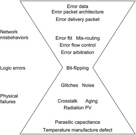
Fig. 13. Physical failures, logic errors, and network misbehaviors.
The comparison of the physical failures, logical errors, and network misbehaviors is shown in Fig. 13.Under the impacts of radiation, temperature, parasitic capacitance, and manufacture defects, physical failures appear in ICs, including crosstalk, radiation, aging, and process variation. Physical failures affect the delay and noise of signals, which result in signal flips as well as logic errors. The logic errors cause the misbehavior of network, which results in misrouting, error data, and damaged packet structure.
The physical failures and logic errors suffered by NoCs are the same as other ICs, and the models are common. However, network misbehaviors are unique for NoCs because they have close relationships with network behaviors and theory.
From Fig. 13, it is obvious that the logic errors have strong advantages than physical failures and network misbehaviors on describing faults. The description of physical failures cannot be unified because the models of different phenomena are different. Moreover, a lot of technology parameters and detail circuits parameters are involved in the complicated calculation, which cost a lot of time and power. Network misbehavior has a close relationship with both of logic errors and network traffic distribution, arbitration, and routing algorithm. Analyzing the model of network misbehaviors increases the complexity of fault-tolerant designs.
Logic errors only include one single phenomenon, which is bit-flip. The statistic characters can be described by the failure rate and MTTF while the temporal and spatial distributions can be described by a probability distribution,e.g., Markov processing. Thus, logic errors play important roles in the research of fault-tolerant NoCs.
4. Fault Diagnosis Methods
Fault diagnosis methods can detect the error signals and network misbehaviors in NoCs, and determine the reason and location of faults. The design of fault diagnosis methods involves test methods and test strategies. Test methods activate and capture the faults by test vectors. Only a few works have been published on test strategies.Many works proposed test methods for NoCs specially or proposed methodologies to design test vectors for digital circuits. Test strategies aim at reducing the impact on system performance from the test by scheduling and managing test procedures.
Fault diagnosis methods can be classified into active detection methods if test vectors are injected into circuits under test, otherwise, they are called passive detection methods.
4.1. Passive Detection Methods
Passive detection methods do not inject test vectors into circuits. Instead, the delivered data is used as test vectors. Two typical passive detection methods are the error detection code (EDC) used in the data paths and the checker used in the control paths.
Faults on the data path can directly change the data in flits. EDC can detect these error bits[27]-[32]. Encoders and decoders usually place at the output ports of input buffers to detect the faults introduced by crossbars, wires, and input buffers, as shown in Fig. 14[28]. The parity check code (PCC)[29], Hamming code[30],[31], and cyclic redundancy check (CRC)[32]are the most commonly used coding methods in NoCs. EDC introduces both area and power overhead by encoders, decoders, and redundancy bits.

Fig. 14. Error detection codes in NoCs.
The correction behaviors of the control path can be abstracted as a series of rules. If the behaviors of networks break these determined rules, faults must occur. The checkers based on rules can be implemented by the simple logic like comparisons and decoders so that the overhead of checkers is much lower than the circuit under test.References [26] and [33] proposed two similar designs for the checker. Each checker only covers one module on the control logic, like the routing calculator and arbiter.The checker checks whether the input and output signals of the module under test following the rules. If the rules are broken, an alert is given out as shown in Fig. 15. A kind of stack-at-port faults was defined in [34]which can be checked by the source address,destination address, and routing direction[34].
The advantages of EDCs and checkers include low hardware overhead and simple implementation. However,the EDCs and checkers can only support coarse-grained fault location and diagnosis. Most importantly, passive fault detection methods cannot cover all faults. On one side, passive detection methods can only detect the used module because passive detection methods use delivered data as test vectors. A module would not be detected if no data through this module. On the other side, specified test vectors are necessary to active faults like crosstalk but delivered data cannot address this requirement most time. Therefore, passive fault detection methods are suitable for the network misbehaviors and data errors introduced by transient faults. The active detection methods should be triggered for fine-grain fault diagnosis after the passive detection methods detect faults.
4.2. Active Detection Methods
Active detection methods inject well-designed test vectors into the circuit under test to activate and capture faults. Built-in self-test (BIST) is one of the typical active detection methods.
BIST circuits consist of test pattern generators (TPGs) and test pattern analyzers (TPAs). TPGs locate at the inputs of the circuit under test to generate well-designed test vectors and drive the circuit under test. The TPAs locate at the outputs of the circuit under test to detect and diagnose the faults by analyzing the circuit’s response to test vectors. The critical issue of BIST is effective test vectors. All the misbehaviors must be considered during the design of test vectors so that maximum fault coverage can be provided by lest test vectors.

Fig. 15. Checkers in NoCs.
The inputs and outputs of the circuit under test switch between the regular channel and test channel. The range formed by multiplexers (Muxs) and demultiplexers (Demuxs) is called the test wrapper[35]. Fig. 16 shows commonly used test wrappers in NoCs. Test wrappers can only contain one functional module like the routing calculator or the arbiter as shown in Fig. 16 (a)[28], which is suitable for the control path test. In the wrapper shown in Fig. 16 (b),TPGs and TPAs are all located in the neighbor routers of the router-under-test (RUT). Another similar test wrapper is shown in Fig. 16 (c). TPGs are located in neighbor routers while TPAs are located in the RUT. Test wrappers can also contain a group of wires as shown in Fig. 16 (c)[36]. The wires have a high coupling relationship with input buffers, output buffers, and the control path. So buffers and the control path do not need to work if the wires are under test. Thus, all these components with high coupling can be packaged into one test wrapper as shown in Fig. 16 (d)[37],[38].
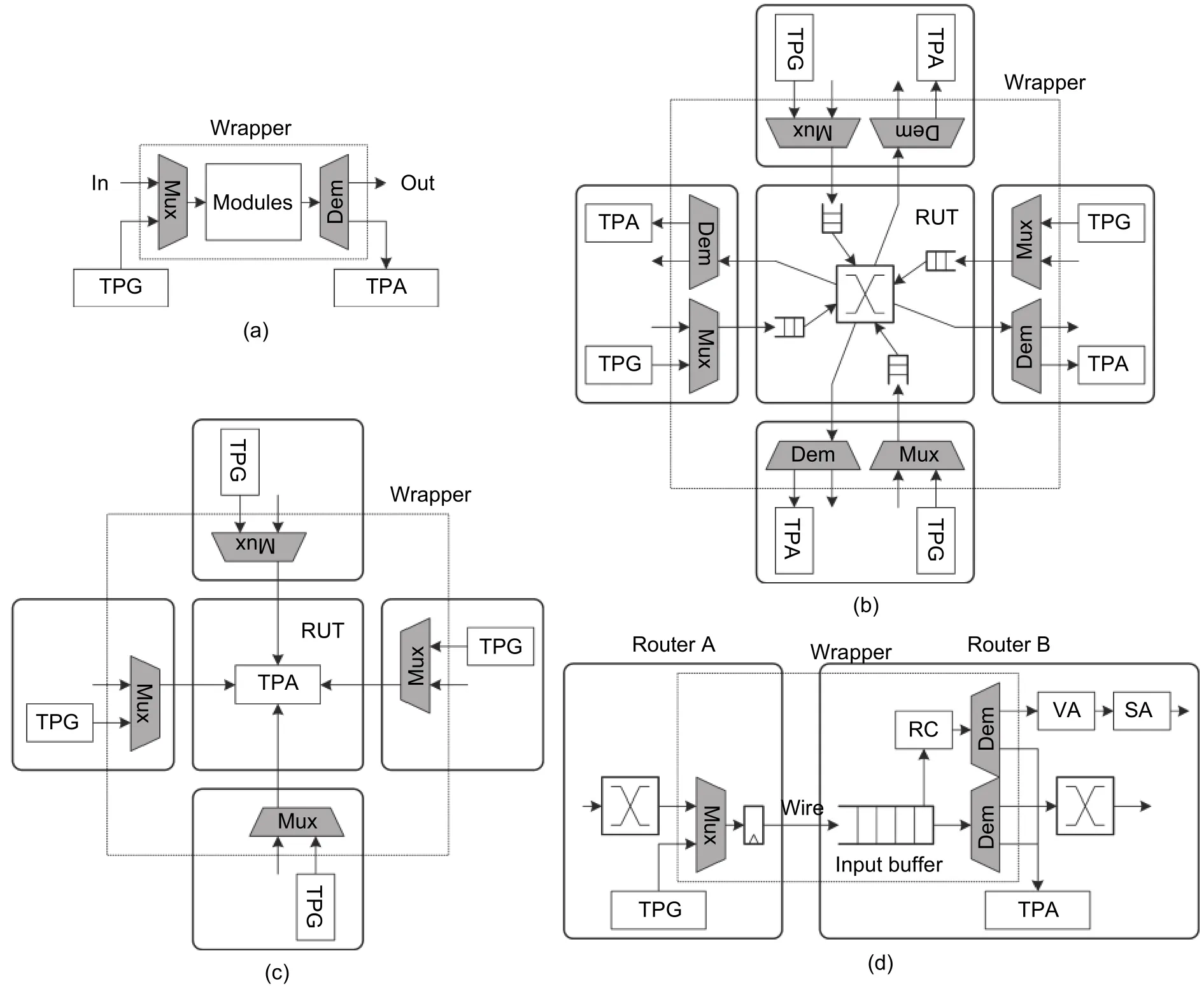
Fig. 16. Test wrappers for BIST in NoCs: (a) test wrapper only contains one function module, (b) test wrapper contains one router and test vectors deliver through the RUT, (c) test wrapper contains one router and test vectors deliver from neighbor routers to the RUT, and (d) test wrapper contains wires, input buffers, output registers, and the control paths.
Reference [39] proposed the test method containing the RUT and connected ports in neighbor routers as shown in Fig. 16 (b). Test vectors are injected by the TPG in one neighbor router, delivered through the RUT and accepted by the TPA in another neighbor router[40],[41]. The research group led by D. Bertozzi proposes another test method as shown in Fig. 16 (c). Test vectors are injected by TPGs in neighbor routers and analyzed by TPAs in the router-under-test. Reference [40] proposed to test the data paths, arbiters, and routing calculator by delivering three different test packets between the RUT and neighbor routers. Reference [42] finished a test wrapper contains one entire router based on IEEE 1500 standard.
As shown in Figs. 16 (b) and (c), test wrappers for one RUT need to put several TPGs and TPAs in the routers so that the area overhead and power consumption increase. The overhead can be reduced significantly if the TPGs and TPAs in NIs can be reused for the test. Reference [43] proposed the test wrapper based on 2×2 subnetworks. Different test vectors can realize the test of links and routers.
Test wrappers can also contain the entire NoC. Test packets are injected and analyzed by TPGs and TPAs in NIs. In this situation, fine-grain fault detection and diagnosis are not possible. This kind of test methods arranges test packets through specified paths and counts the reliability of packets. Then, the location of faulty links and routers can be determined by cross-location. Reference [44] suggested arranging straight paths, XY/YX turn paths,and NI paths. Reference [45] suggested arranging strange paths, paths with single turning, and U/Z-shape paths with double turns. Reference [46] arranged 16 paths to test the crosstalk on every link in a 4×4 mesh NoC.Reference [47] proposed to deliver test packets by the broadcast routing algorithm. The broadcast routing can significantly reduce the overall time of test procedures compared with unicast routing. Reference [48] proposed another test method based on broadcast routing for irregular topology.
Due to the high fault coverage and fine-gain fault diagnosis, BIST is more suitable to detect and diagnose intermittent and permanent faults. After the source and location of faults are diagnosed, fault recovery methods are triggered to remove the impacts on systems.
4.3. Test Strategies
Test strategies schedule and manage test procedures for specified test methods. It is not necessary to design test strategies for passive fault detection methods because passive fault detection methods work all the time.
Active fault detection methods need test strategies. BIST can be started directly after the chip is manufactured.Off-line tests can detect the manufacturing defect effectively[38],[41]. BIST can be used while the chip is used, which is called the on-line test. On-line tests can detect the faults due to aging. On-line BIST can be classified into the sporadic and periodic BIST. The sporadic BIST can be triggered by the faults reported by the checker[49], or the error flits found by EDC. For the routers with a low utilization rate or faults need specified test vectors, the periodic BIST can increase the fault coverage[50]. Increasing the test frequency of periodic BIST can reduce the failure rate significantly.
Because the network operates the normal data delivery and BIST at the same time, on-line BIST must face the impact on the system performance due to tests. First, the circuit under test has to be isolated from the network so that the routers or links under test cannot work. The integrity of the NoC is damaged. Then, the IP connected to the RUT is also isolated from the network, which leads to the damage to the integrity of system computation resources.At last, for memory-share many-core systems, a part of the shared memory is also isolated. The application program has to be delayed for a long period due to the cache coherence and data dependency.
Most proposed BIST methods for NoCs do not specify the test strategy. The normal operation of NoCs has to be completely stopped definitely, which leads to a significant impact on the system performance. Some researchers try to overlap the test procedures with the normal data delivery. References [39] and [51] proposed two different test strategies with token-based test sequences. Both of them use snake-like test sequence as shown in Fig. 17 (a). In the test strategy proposed by [51], no interval existed between the testing of two routers. Routers are tested continually. In the test strategy proposed by [39], one router did not start test procedure directly after it got token. Instead, the router has to wait for 10000 flits through the RUT to avoid network congestion. Although these two proposed methods can maintain the regular operation during tests, the impact on system performance is obvious as well. Reference [39] reported that the average network latency under PARSEC benchmark[52]increased 4 times when the test interval reduced from 20000 flits to less than 2000 flits. The apparent performance loss limits the further improvement of test frequency.
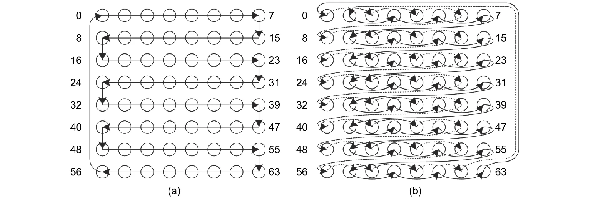
Fig. 17. Test sequences: (a) snake-like and (b) odd-even.
Therefore, the test strategies should aim at minimizing the impacts introduced by the test and increasing the test frequency as well. Reference [49] reduced the impact on system performance by combining the off-line test and online test. The NoC is divided into several subnetworks with EDC on edges. The EDC detects the errors within the subnetworks by checking the flits cross the subnetworks. Then, the faults are diagnosed in detail by offline BIST within a subnetwork. This method avoids the situation in which the BIST operates but no fault is detected.
Under the realistic traffic, the utilization rate of links is not high so that there are many slots without flits to deliver. Reference [53] proposed to use these free slots for tests. This method does not need to isolate links away from the network and avoid blocking the normal communication. As a result, the impacts on the network are reduced.
The TARRA test strategy[54]can reduce the impact on system performance and increase test frequency significantly. The test wrapper implied by TARRA contains the RUT and connected ports in neighbor routers.TARRA makes sure that the IP core and shared memory connected to the RUT can access the NoC during test procedures by implying the reconfigurable router architecture and adaptive the routing algorithm comprehensively.TARRA also proposed an odd-even test sequence as shown in Fig. 17 (b) so that the network can still achieve 100% packet delivery and ignorable network congestion when the number of RUTs at the same time equals to the half of network width.
Reference [55] classified the fault diagnosis methods in the view of network layers and proposed a cross-layer organization method for fault diagnosis methods. The diagnosis protocols (DP) based on software locate the fault network components by accepting and analyzing data packets in the transport layer. Function diagnosis (FD)analyzes the functional errors of routers by specified packets in the network layer and data link layer. Structure diagnosis (SD) determines the failure logic gates and wires in routers and links. DP, FD, and SD can be combined by detecting sequence from up to down: DP+FP, DP+SD, DP+FD+SD, and FD+SD.
Reasonable test strategies can reduce the performance loss introduced by test procedures, increase test frequency, and provide the positive impact on system reliability. One test strategy is assigned to one test method or one kind of test methods. The solution of test strategies is beyond the range of traditional design-for-test design in fact. Therefore, the test strategies do not catch enough attention from researchers.
4.4. Summary and Discussion
Both passive and active fault detection methods can detect the faults in the granularity of one module, one router, and the entire network. Also, both passive and active fault detection methods can cover the faults in the data path and the control path.
Passive fault detection methods use the normal data packets as test vectors and detect the faulty packets or the faults activated by packets. Passive fault detection methods are useful for transient, intermittent, and permanent faults. However, the alert signals are always set for permanent faults and long-time last intermittent faults. Active fault detection methods can locate and diagnose faults in fine-grained and are suitable for permanent faults and long-time last intermittent faults.
Passive fault detection methods introduce extra area overhead and power consumption due to EDC circuits and checkers. If the unit is complexity and has a long critical path, the extra pipeline stage is necessary, as the decoder for EDC.
Related to passive fault detection methods, BIST costs much longer test procedure and introduces significant area overhead and power consumption due to complex TPGs and TPAs. Meanwhile, BIST needs to isolate the circuit under test from the network so that the integrity of network resources is damaged and the network performance drops. After all, BIST still an effective fault diagnosis method because it has more benefits in fault coverage and diagnosis.
5. Fault Recovery Methods
Fault recovery methods can reconfigure the circuit architectures, routing paths, and information to improve the reliability of NoCs. Because NoCs provide a variety of redundancy resources, many different fault recovery methods have been proposed for NoCs.
Fault recovery methods can be classified into hardware redundancy, information redundancy, and time redundancy according to the used redundancy resources[56]. Additionally, fault recovery methods belong to the data-link layer, the network layer, or the transport layer according to different protected targets. Fig. 18 shows the classification of fault recovery methods.

Fig. 18. Classification of fault recovery methods based on network layers and redundancy resources.
5.1. Hardware Redundancy
Hardware redundancy needs a few same copies of protected hardware. Passive hardware redundancy methods decide the correct result based on the results provided by all hardware copies as shown in Fig. 19 (a).Triple modules redundancy (TMR) is a typical passive hardware redundancy. Active hardware redundancy methods switch from the faulty component to the correct redundancy component if faults are detected as shown in Fig. 19 (b). The reconfigurable router architecture and spare wire (SW) for the data-link layer as well as the faulttolerant routing algorithm (FTR) for the network layer are typical active redundancy methods.

Fig. 19. Passive and active hardware redundancy: (a) passive and (b) acttive.
A. TMR
TMR needs three copies of the protected circuit to process or transfer the same information. The same result provided by two or three copies is decided as the correct result. TMR is a very simple and effective fault recovery method. In NoCs, TMR is usually used to protect critical control signals, for example, the handshake signals and flow control signals between routers[57]-[59].
The major advantages of TMR are the simple design and high fault-tolerant capacity. It is not necessary to design different redundancy circuits for TMR because TMR uses three same circuit units. The voting circuit is also simple and costs very little area. However, the entire hardware of TMR is 3 times of the original circuits because TMR copies the protected circuit completely. Meanwhile, the power consumption of TMR is also increased to 3 times because every copy needs to do the same operation.
B. Reconfigurable Router Architecture
In NoCs, modules have close couples with each other. Other modules also cannot be used if one module within routers or links has faults. For example, single point faults occurred on links would disable the entire path from one router to its neighbor router, including the input buffer, output register, and control logic connected to the faulty link.It is not cost-effective to abandon the entire router or link due to one faulty module. Reconfigurable router architectures can reorganize the available resources to guarantee the correctness of data delivery and extend the lifetime of the entire chip.
One way to design a reconfigurable router architecture is providing redundancy resources to replace the faulty modules. Reference [60] proposed to provide one redundancy router to each router. When the protected router is faulty, the redundancy router is active. In Vicis[28]and REPAIR[27], one redundancy bus shared by all input ports and output ports is provided to bypass the faulty crossbar. The bypass bus can maintain the normal function of the router but does not introduce excessive hardware overhead. Additionally, REPAIR[27]uses backup input buffers to replace faulty input buffers while Shield[61]uses backup routing calculators to replace the faulty routing calculators.
Reference [62] proposed the SW method for links. The redundancy wires are used to replace the faulty links to maintain the communications bandwidth.
Similar to TMR, redundancy resources introduce area overhead and extra power consumption. Moreover, the redundancy modules are placed very close to the protected modules to reduce the distance of connection wires considering design rules of the layouts. Thus, redundancy modules and protected modules suffer the same physical defect, so that the redundancy modules have the probability of exceeding expectations to occur similar physical failures. Therefore, the redundancy modules should be simpler compared with the protected modules to reduce the failure probability and extend the lifetime.
Another way to design a reconfigurable router architecture is to make full use of the redundancy resources and living resources already provided by NoCs. In [28] and [63], a method is proposed to avoid the faulty units in input buffers automatically by adjusting the write and read pointers in the buffers so that the data is stored in the living units correctly. Shield[61]proposed a comprehensive reconfiguration method to fix the faults in crossbars, virtual channel allocators, and switch allocators, including managing the connections between the crossbar and output ports, reusing the virtual channel allocator signals, and fixing the switch allocator signals. Vicis[28]managed the connections between input ports and input buffers.
QORE in [64] provided 4 links between routers. The direction of all links can be changed to address different traffic distributions and fault distributions. QORE also provided a backup ring path to maintain the communications under massive faults. Reference [65] reorganized the network into a regular network without faulty routers based on the principle to minimize the maximum flow.
Utilizing the living modules to reconfigure the routers does not introduce extra redundancy modules. However,the complex reconfigurable architecture raises new challenges to designers and introduces the new reliability risk.C. FTR
Relative to buses, NoCs already provide a large number of redundancy resources. The paths with the minimal distance between the source and destination are called minimal paths. For a mesh network, there are (ΔX + ΔY)! /(ΔX)!(ΔY)! minimal paths between the source and destination if the distances on east-west and north-south directions are ΔX and ΔY. Thus, it is possible to choose another path to avoid faulty links or routers. If the nonminimal paths are allowed, there are paths without faulty routers or links between the source and destination except they are isolated by faulty components in topology.
FTR can choose a path without faulty routers and links from the source to the destination. At the same time,FTR needs to consider the packet latency and transmission distance to achieve a balance between network performance, power consumption, and reliability. FTR is always a hot research topic in the field of fault-tolerant NoCs, and many works are published every year.
The routing path can be determined in the source router at one time, which is called source routing, or in each router one-step by one-step, which is called distributed routing. If using source routing, packets follow the path determined in the source router. Thus, routing information is necessary to be added to the head flit. Source routing cannot respond to the network status in time, like traffic congestion. Distributed routing can fix the shortage of source routing by calculating the direction of the next step in each router. As the payoff, more delay is added due to the routing algorithm.
Routing algorithms can be implemented in two different ways: Rule-based and learning-based. The rulebased routing algorithm can be described as a series of routing selection rules according to the packets’information and limited networks’ status information. The rule-based routing algorithm can be implemented by simple logic circuits, like decoders, comparators, and multiplexers. Learning-based routing algorithms collect the status of routers and links and determine the paths based on a kind of learning algorithms. Learningbased routing algorithms cannot be implemented by simple logic circuits. Instead, each router maintains a routing table to store the forward directions. The learning algorithm updates the items in the routing table.
Under wormhole switching, packets are blocked if there is not enough space to accept this packet in the next router, which leads to the resource dependency between routers. Resource dependency can release automatically as the packets deliver. However, if the resource dependency forms a ring, the resource dependency will not release automatically, which is called deadlock. Even worse, the deadlock will extend to the entire network leading the whole network to be blocked. Hence, the deadlock is one of the most severe misbehaviors of NoCs. In a mesh network, the turn model can be used to analyze that whether the routing algorithm is deadlock-free or not[66]. If the turns appeared in a routing algorithm form a ring, there is a large probability of deadlock as shown in Fig. 20.
Source routing can determine the path if the fault status of all routers or links is known. Resilient quality-ofservice network-on-chip (RQNoC)[67]added bypass heads to packets to turn around the faulty links. Reference [68]proposed a communications protocol to search an available path before the data delivery. Then packets deliver through the searched path.

Fig. 20. Turn models: (a) classic turn model and (b) turn model with virtual channels.
As the trade-off between source routing and distributed routing, the fault tolerant with localised rerouting (FTLR)scheme[69]proposed a partial source routing algorithm. Before arriving at the routers connected to faulty links,packets are delivered following the XY routing algorithm. After arriving at faulty links, packets turn around the faulty link clockwise or anticlockwise. The necessary turns are stored in the head flits.
Most FTRs choose the distributed routing algorithm. Both rule-based and learning-based routing algorithms can tolerate faulty routers and links. Rule-based FTR should consider the fault status of routers or links in the routing selection rules. There are much researches about rule-based FTR, and it is impossible to review all of them in this article.
The fault information known by routers has a direct relationship with the fault-tolerant capacity and network performance. Most FTRs only use the fault status of neighbor routers or links, which can be provided by fault diagnosis methods directly. Some other FTRs try to provide more possible paths by extending the fault-aware region. In the fault-on-neighbor (FON) aware routing algorithm[70], each router knows not only the fault status of neighbor routers and links but also the status of links connected to neighbor routers. In ZoneDefence[71], routers hold the marks for the farthest distance in north and south directions so that packets can avoid these faulty routers before receiving the neighbor routers of faulty routers. In the network-level testing strategy with adaptive routing and reconfigurable architecture (TARRA)[54], fault status of one router is propagated to one 3×3 district with this router in the center so that the performance loss due to the routing algorithm is significantly reduced.
The complexity of rules is another factor limiting the fault-tolerant capacity of FTRs. In general, more complex rules can achieve better fault-tolerant capacity but introduce more area overhead. As each virtual channel needs one exclusive routing calculator, the area overhead and power consumption introduced by FTRs are amplified.
Limited by the known fault status and complexity of rules, rule-based FTRs cannot make the global-optimized decision. Thus, the fault-tolerant capacity of FTRs is limited, which has been proved by most FTRs. When there are dense faulty links in NoCs, FTRs cannot guarantee correct packet delivery although the network is connected in topology. Unfortunately, no theory can explain how faulty status information and selection rules impact the faulttolerant capacity and network performance by now.
Dynamic programming[72], Q-learning[73],[74], and ant colony optimization (ACO)[75]have been used in the learningbased routing algorithm. Relative to rule-based routing algorithms, learning-based routing algorithms can achieve better fault-tolerant capacity because the decisions are made based on more fault status information. The fault status may not propagate explicitly. Instead, the fault status are propagated in the metrics defined by learning algorithms. Knowing the status information of the entire network benefits the routing decision to avoid faulty routers and links. Moreover, by defining more complicated metrics, learning algorithms can optimize not only the reliability but also the network congestion and quality of service.
The research about rule-based FTRs is still the mainstream due to the easy innovation and implementation.Many works are published every year. However, the research about learning-based FTRs has the higher impact because learning-based FTRs can achieve better fault-tolerant capacity and joint-optimize multiple targets.
5.2. Information Redundancy
Information redundancy methods copy the information directly or through specified algorithms. Most common information redundancy methods include flooring routing (FR) for the network layer and the error correcting code(ECC) for the data-link layer and transport layer.
A. Flooding Routing (FR)
Flooding routing protocols directly transfer several copies of the delivered packet in the network. One packet is accepted correctly as long as one copy packet is accepted correctly. Obviously, FR can achieve excellent reliability.However, FR injects many redundancy packets into the network so that the traffic load increases heavily and the network performance is reduced.
Researchers have proposed different flooring strategies to balance the fault-tolerant capacity and extra traffic load. Reference [76] implied the random probability p as the threshold for copying packets. Reference [77]proposed the adaptive stochastic routing (ASR) algorithm to adjust the threshold p. Reference [78] proposed the random walk and N walk strategies. Reference [79] proposed the low traffic pass reuse (LTR) routing algorithm that generates 2 copy packets for each packet. One of copying packets delivers under the XY routing algorithm while the other delivers following the YX routing algorithm.
B. ECC
ECC is the most common fault recovery method for the data path. ECC increases the reliability by redundancy information. Encoders add redundancy bits to the original information. Decoders check the original and redundancy information and correct the error bits. Limited by the area overhead and power consumption, NoCs cannot imply complex ECCs. Most time, single error correction and double error detection (SEC-DED) codes are implied.Common coding methods used in NoCs include the Hamming codes[80],[81](as well as the treduced Hamming code[82]and extended Hamming code[83]), Hasio code[59], Bose-Chaudhuri-Hocquenghem (BCH) code[84], and cyclic redundancy check code (CRC)[81],[85]. On one aspect, designers try to optimize the coding methods used in NoCs further to achieve better error correcting capacity. On the other aspect, designers try to optimize the location and utilization of ECC methods to achieve the trade-off between the reliability and overhead.
One popular method to improve the error correcting capability is the product code[82],[86]. Arrange the transferred data in a matrix and imply block codes in row and column separately. The error bits can be located based on the results of the row coding and the column coding. The Hamming code based product codes (H-PC)[82]implied Hamming(38,32) and Hamming(7,4) in row and column directions. Reference [86] arranged wires into an 8×8 matrix and implied light-weight parity coding.
Because the faults always appear on adjacent bits like crosstalk, ECC should improve the capacity to correct the adjacent error bits especially. Interleave rearranges the order of transmission wires so that the adjacent bits become nonadjacent bits at the decoders. Thus, the common ECCs can also correct adjacent error bits. The multiple-continous-error-correction-code MCECC(96,32) combines Hamming(7,4), pattern forbidden code FPC(5,4),and interleave, so that MCECC(96,32) can correct 14 bit adjacent errors at most[87]. Reference [88] implied different coding methods for routing information and payload information because the routing information is more critical for the correct data transmission. This code can correct single bit errors and detect two adjacent bit errors in routing information and payload information. Moreover, this code can correct two adjacent bit errors in routing information and the adjacent of routing information and payload information.
Crosstalk avoid coding (CAC) can remove the adjacent bit errors by avoiding the occurrence of crosstalk. A.Ganguly and P. Pande proposed JTEC and the crosstalk avoiding double error correction code (CADEC)respectively that can correct error bits and avoid crosstalk[89]. CADEC implied the Hamming(38,32) code to correct errors and implied the spare wire to avoid crosstalk. CAC also has benefits on power consumption.
ECC introduces area overhead and power consumption obviously. It is worth to make a trade-off between reliability and overhead. Reference [90] compared the reliability and power consumption of data transmission implying the SEC code, SEC-DED code, detection code, cyclic code, and parity code. Because the power consumption of encoders and decoders plays the dominant role, the power consumption of different coding methods under different failure rates does not show a stable trend. Reference [30] compared the area overhead,power consumption, and critical path implying Hamming codes with different lengths. The result shows the code with the short length can fully reduce above parameters. Authors suggested to choose the code with short words and implied interleave to correct adjacent bit errors. Reference [91] compared the area, power, critical path, and reliability of the Hamming code, BCH code, and RS code. The conclusion is that complex coding methods, like BCH and RS with interleaving, can achieve better reliability, but using these codes have to cost larger area and reduce the circuit frequency.
There are several strategies to place ECC units in NoCs. Among them, the switch-to-switch (S2S) and end-toend (E2E) are the most common used ECC location strategies. E2E locates the encoders and decoders in NIs.Data can be checked and corrected only after received by NIs. Except for NIs, S2S also places encoders and decoders in routers so that data can be checked and corrected in every router. Therefore, S2S ECC belongs to the data-link layer, while E2E ECC belongs to the transport layer.
The circuits between the encoder and decoder are defined as the protection domain of ECC. Reference [92]summarized the location methods for E2E ECC and S2S ECC. E2E ECC locates the encoders and decoders on the local ports. The protection domain contains the entire path from the source to the destination as shown in Fig. 21 (a). One kind of S2S ECC locates the encoders at the output ports and the decoders at the input ports.There is no encoder or decoder at local ports. Therefore, the protection domain contains the link between routers as shown in Fig. 21 (b). Another kind of S2S ECC locates the encoders at the local input ports and the decoders on other input ports, so that the protection domain contains the data path in the router and the link to the next router as shown in Fig. 21 (c). In general, S2S ECC can achieve better reliability than E2E ECC, but more area overhead, power consumption, and performance loss are necessary.
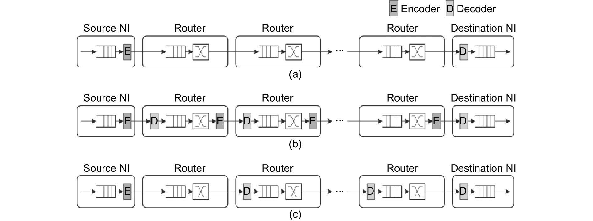
Fig. 21. Location strategies for ECC: (a) end-to-edd ECC, (b) switch-to-switch ECC with both encoders and decoders in routers, and (c) switch-to-switch ECC with only decoders.
To make a trade-off between reliability and overhead, ECC location strategies can adaptively switch between S2S and E2E. Reference [83] proposed the design to switch between E2E Hamming(39,32) and S2S Hamming(8,4) according to the count of faulty flits. Reference [81] proposed that the decision tree can be used to choose the most suitable location strategy among no ECC, E2E CRC-32 with retransmission (RT) and S2S Hamming(72,64) with retransmission according to the utilization, aging rate, and temperature in real time.
The runtime adaptive scrubbing (RAS)[59]switches between CRC, weak ECC (RAS-W), strong ECC (RAS-S),and power-efficient ECC (RAS-P) strategies according to the frequency of faulty flits and link utilization rate. E2E CRC32 is used to protect data. If the faults are serious, S2S Haiso(39,32), interleave, and data copy are active to improve the reliability. Other works proposed the designs to turn on/off S2S ECC[93]or switch the coding methods[58],[94]according to the frequency of faulty flits and the status of neighbor routers. For example, 4 groups of Hamming(12,8) or 1 group of Hamming(38,32) are used under a high fault rate or low fault rate. The fault adaptive and low power rnethod (FALP)[95]switches between the parity code and the Hamming code.
To reduce the area overhead introduced by two or even more different encoders and decoders for adaptive ECC, [80] proposed a multi-mode reconfigurable encoder. Because the parity-check matrix of Hamming(21,16) is a part of the parity-check matrix of Hamming(38,32), the encoder of Hamming(21,16) can be used to design the multi-model encoder with a few additional XOR and Mux gates. This idea can be used in other Hamming codes as well. The multi-model encoder can reduce the area overhead related to two encoders.
Limited by the area overhead, the error correction capacity of ECCs used by NoCs is also limited. ECC cannot correct the error data all the time. Therefore, ECC usually uses together with RT.
5.3. Time Redundancy
Time redundancy methods can mask the impact of faults by operating the same processing on same circuit several times. The data for processing may not be same. Time redundancy methods introduce extra delay and cause performance loss. The split link (SL) for the data-link layer, repeating operations for the network and data-link layer, as well as RT for the transport and data-link layers, all benefit from time redundancy.
A. SL
Different from SW, SL does not provide extra wires. The faulty wires are abandoned, and the left wires are used to continue data transmission. SL has to scarify the network performance and increase the complexity of circuits.Because the bandwidth in one cycle is reduced due to faulty links, the network performance drops. On the other side, SL needs extra circuits to adjust the architecture of packets, including the pipeline control logic, flow control logic, and buffers[58],[94].
The partially-faulty link recovery mechanism (PFLRM)[96]proposed another more common method to rebuild packets for SL. After locating the fault wires, the transmitter sends the copy of data for several times while cyclic shifting every time. Therefore, every bit can be transferred on living wires for at least once. The receiver rebuilds the data by shifting bits back.
B. Repeating Operations
Transient faults on the control paths can be masked by operating the same processing several times.Reference [97] proposed to detect faults by calculating routing twice. If the results of twice operations are same, the results are determined as the correct result. Otherwise, run routing calculation for the third time and then vote for the correct result. For networks with long packets, twice routing calculating does not introduce obvious delay.However, for networks with short packets, performance loss introduced by twice routing calculating is obvious.
The soft error tolerant NoC router (STNR) pipeline architecture is designed for soft errors[98]. STNR needs two times of routing calculation, virtual channel arbitration, and switch arbitration to detect faults. The second time operation can reuse the free pipeline stage. The virtual channel arbitration for the first time and the routing calculation for the second time can run at the same cycle, while the first time switch arbitration and the second time virtual channel arbitration can run at the same cycle. If the results of operations are not the same, the pipeline rolls back to the faulty pipeline stage and reruns. As shown in Fig. 22, without any faults, STNR introduces one more SA stage. If routing calculation is faulty, extra two pipeline stages are necessary to rollback and redo routing calculation.

Fig. 22. Pipeline stage for repeating operations: (a) pipeline diagram without any faults and (b) pipline diagram with faulty routing calculation.
C. RT
If the faults in packets exceed the fault recovery capacity of routers and NIs, these packets have to be abandoned and retransmitted. RT is a common fault recovery method to recover the information. Corresponding to ECC, RT can be utilized as S2S RT and E2E RT, too[99](Fig. 23).
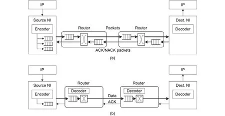
Fig. 23. RT architectures: (a) switch-to-switch RT and (b) end-to-end RT.
S2S RT (Fig. 23 (b)) needs additional handshake signals and flow control logic between routers. When the router delivers data to another, the previous stage router will not stop driving links with the same data until the next stage router accepts the data correctly, as shown in Fig. 24 (a). After successful transmission, the previous stage router removes the data from the RT buffer.
E2E RT can be triggered by acknowledge/negative acknowledge (ACK/NACK) packets or time-out. NIs will save one backup for each sent packet. When the NI accepts a packet correctly, the NI sends one ACK packet to the source NI of this packet. The source NI removes the backup of the specific packet from the buffer after receiving the ACK packet. If the NI accepts a faulty packet, the NI will send one NACK packet to the source NI of this packet. The source NI adds the specific backup packet back to the inject queue after receiving the NACK packet. Fig. 24 (a) shows the timing diagram for ACK/NACK RT.
The ACK/NACK packets can be faulty or lost as well, so RT needs the predetermined time window. Packets are retransmitted even if no valid ACK/NACK packets are received at the deadline, which is called time-out RT.Fig. 24 (b) shows the timing diagram for it. Time-out RT can be used separately as well as together with ACK/NACK RT. Separate time-out RT increases the delay for faulty packets but reduces the traffic load.
The NIs implied E2E RT needs larger buffers to store all the backup packets and realize the packet reordering related to the NIs without RT. Due to the complexity of implementation, the RT mechanism implied in NoCs is much simpler than the RT mechanism used on the Internet. E2E RT is useful for transient faults and intermittent faults. The reliability of data delivery can be increased significantly. However, RT does not work under the high failure rate because the retransmitted packets and ACK/NACK packets can be faulty as well. Moreover, RT increases the traffic load in the network and reduces the throughput and drops network performance.
5.4. Summary and Discussion
Table 2 summarizes the implementation, protection domain, and effective fault category for fault recovery methods. In Table 2, “+” or “-” means the fault recovery method is effective or not for this kind of faults respectively. “[+]” means that the fault recovery method is effective for this kind of faults, but this method is not recommended due to the overhead.
The protection domain is defined as the area in which the faults can be corrected while the implementation points to the reconfiguration methods. For example, the protection domain of ECC contains the data path between encoders and decoders, while ECC directly corrects the fault flits or packets.
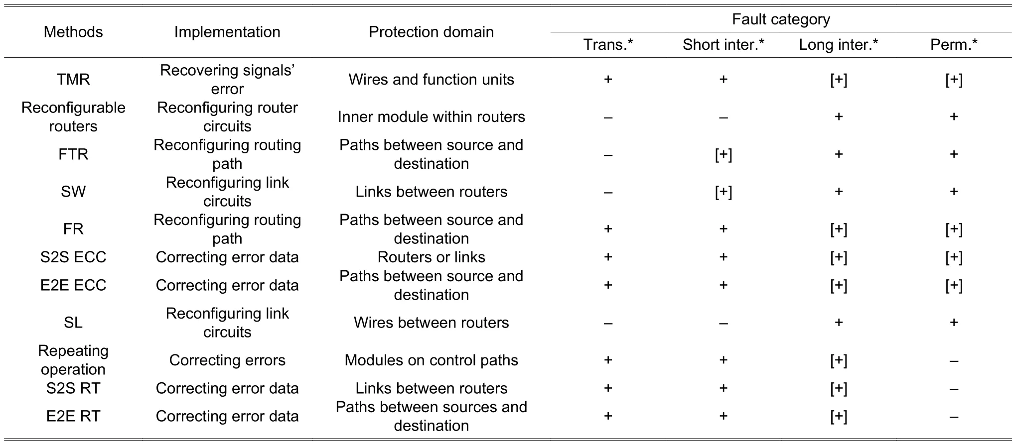
Table 2: Summarize of fault recovery methods for NoC
In the view of the protection domain, fault recovery methods can be classified into three granularities: 1) FTR,FR, E2E ECC, and E2E RT protect the paths between the source and destination; 2) SW, SL, S2S ECC, and S2S RT protect the routers or links between routers; 3) TMR and reconfigurable router architectures protect modules in NoCs.
In the view of implementation, fault recovery methods can be classified into three categories as well. First, fault recovery methods fix faults by reconfiguring the circuits, including the reconfigurable routers, SW and SL. Then, the routing paths are reconfigured to turn around the faulty routers and links, like FTR and FR. However, both reconfiguring circuits and reconfiguring paths cannot fix the faulty flits and packets. At last, fault recovery methods directly fix the faults in flits and packets by TMR, ECC, repeating operations, or RT.
In the view of the fault category, fault recovery methods are suitable for short-time faults (transient faults and short-time intermittent faults) or long-time faults (long-time intermittent faults and permanent faults). Fault recovery methods suitable for short-time faults usually fix the fault flits and packets to guarantee the data delivery. Because the last time of faults is short, the power consumption and performance loss would be significant due to the high frequency of reconfiguration if implying fault recovery methods to reconfigure circuits and paths. Fault recovery methods suitable for long-time faults usually reconfigure circuits or paths to replace or avoid the faulty modules,routers, or links. Although it is still useful to imply fault recovery methods which directly fix the faults, significantly power consumption and performance loss are introduced because many fault packets need to be fixed if the faults last for a long period.
Therefore, fault recovery methods have limitations on implementation, the protection domain, and fault category. There is a complementary relationship between different fault recovery methods. For example, to protect the paths between the source and destination, FTR reconfigures the routing paths and aims at long-time faults,while E2E RT directly corrects the fault data and aims at short-time faults. Hence, cross-layer integration of fault recovery methods can improve the reliability of NoCs.
Table 3 lists the area overhead, power consumption, and performance loss introduced by commonly used fault recovery methods. The additional circuits are added to implement fault recovery methods, including backup modules, buffers, and control logic. Power consumption includes the power of additional circuits, power due to repeating operations, retransmission, and the extra distance to turn around faulty routers and links due to FTR. The actual bandwidth of NoCs also reduces because fault recovery methods reduce the available resources and increase the competition. Meanwhile, the latency of packets rapidly increases because repeating operations and retransmission increase the traffic load.

Table 3: Overhead of fault recovery methods for NoC
At last, the reliability issue of additional circuits should not be ignored. The fault recovery circuits and the protected circuits are manufactured with the same technology and devices. Moreover, the fault recovery circuits are placed very close to the protected circuits in the layout considering the design rules. Therefore, the fault recovery circuits suffer the same reliability risk as the protected circuits. The fault recovery circuits can be faulty as well.
6. Discussion and Conclusion
As a standard on-chip communications architecture, NoCs should provide high bandwidth, throughput, and scalability as well as high reliability. Error data transmission will block the execution of applications and reduce the system performance. Fault-tolerant designs use different kinds of redundancy resources to protect the NoCs and guarantee the correctness of on-chip communications and the system performance further.
In this article, the publications on fault-tolerant NoCs are reviewed to classified their methods and ideas.Moreover, this article pays attention to the overhead of fault-tolerant designs. As a result, this article provides references for designers to build up fault-tolerant NoCs.
The entire article can be divided into two parts. The background knowledge for fault-tolerant NoCs is introduced in the first part. At the start, a short brief of NoC architectures is given, including the topology, hardware architecture, wormhole switching, and credit-based flow control. Then, the fault models to describe the physical failures, logic errors, and network misbehaviors are introduced. The logic errors are the abstraction of physical failures while the network misbehaviors are the further abstraction of the logic errors. However, logic errors are uniform and simple for description and discussion, so logic errors are used very commonly in the fault-tolerant design.
The second part focuses on summarizing published fault diagnosis and fault recovery methods. Fault diagnosis methods include two aspects: Test methods to achieve the maximum fault coverage with lest test vectors and test strategies to minimize the impacts on system performance introduced by test procedures. Fault recovery methods can be classified in two dimensions: Network layers and redundancy resources. Fault diagnosis methods and fault recovery methods indeed improve the reliability of NoCs as well as many-core systems. However, they also introduce non-ignorable area overhead, power consumption, and system performance. Therefore, the fault-tolerant designs should not only address the reliability challenge but also reduce the overhead to achieve the trade-off.
For further research, fault-tolerant designs can improve along these directions.
At first, the fault-tolerant design is not a single objective optimization problem anymore. Instead, the faulttolerant designs should address the multi-objective optimization problems of reliability, overhead, and performance.Those fault recovery methods, which introduce more overhead than reliability improvement, should be abandoned.
Then, fault-tolerant designs should consider the concept of reliability management. Faults should be predicted before they occur. Physical failure models would be integrated into the fault-tolerant designs to give an accurate image of the aging on circuits. As a result, reconfiguration can be implied before the fault occurs to avoid error data.On the other side, releasing the stress also extends the lifetime of circuits. As proposed in [72], the adaptive routing algorithm tends to choose the link with the maximum life budget to balance the utilization of links. The life budget is calculated based on the model of electro-migration.
Further, system integration of fault detection and fault recovery methods is a clear roadmap to improve the reliability. Methods have complementary relationships on protection domains, implementation, and fault categories.Thus, one single fault diagnosis and recovery method cannot form a realistic design. In [100], a methodology to build a cross-layer fault-tolerant design was proposed. The REPAIR[27]and Vicis[28]integrated the reconfiguration router architecture, routing algorithm, and other methods together to provide a comprehensive protection of NoCs.Currently, the connections between different methods and the effectiveness of different methods in the system still need further research and experiments.
At last, fault-tolerant designs not only introduce extra hardware overhead and power consumption but also introduce more fault risk. The fault-tolerant circuits can be faulty as well as protected circuits. Moreover, considering the design rules of the layout, these additional circuits are placed close to the protected circuits to reduce the distance of wires. Therefore, the circuits to tolerant faults suffer the similar physical defects as protected circuits.Reference [101] did the primary research about the location of ECC units considering the faults introduced by encoders and decoders. Overprotection has been proved by this work when the negative effect introduced by ECC units can be stronger than the improvement of reliability lead by ECC. The comprehensive research is necessary for other fault-recovery methods as well.
Acknowledgment
The authors would like to thank the anonymous reviewers for their constructive and helpful suggestions and comments.
 Journal of Electronic Science and Technology2018年3期
- Journal of Electronic Science and Technology的其它文章
- Adaptive Algorithm for Accelerating Direct Isosurface Rendering on GPU
- Enhancing Design of Visual-Servo Delayed System
- Review of Methods of Image Segmentation Based on Quantum Mechanics
- Spatial Channel Sounding Based on Bistatic Synthetic Aperture Radar Principles
- Blood Flow Simulation in the Femoral Artery
- Analysis of RF Feedback Chain Isolation in Wireless Co-Time Co-Frequency Full Duplex
