An innovative trigeneration system using biogas as renewable energy
Grazia Leonzio
Department of Industrial and Information Engineering and Economics,University of L'Aquila,Via Giovanni Gronchi 18,67100 L'Aquila,Italy
1.Introduction
Governmental policies of all the world are finding innovative technologies and processes in order to improve the energy efficiency and to decrease the utilization of the primary energy sources and the greenhouse gas emissions(GHG)[1].In fact,CO2annual emission rose more than 93%between 1973 and 2010:annual emissions were 15.6 Mt.(milliontons)in 1973 and 30.3 Mt.in 2010[2].An efficient process developed to have a lower consumption of the primary energy and lower GHG emissions is the combined cooling,heating and power(CCHP)system,known as the trigeneration power plants.
These high-efficiency electricity,cooling and heating production systems,using also renewable energy,can reduce the rise in CO2emissions,assist in expanding electrical and power systems and substitute for the existing low-efficiency thermal plants[3].
In particular,CCHP plants with small and medium size are used when decentralized or distributed energy systems are need and over the last three decades,these systems have received considerable attention,with the development of different options and alternative configurations.
Compared to the conventional separate systems for energy production(heat by boilers and electric power by central stations)and conventional cogeneration units,the trigeneration system ensures an optimal overall energy production with various technical,environmental and socioeconomic benefits[4-7].The purpose of this innovative system is to ensure lower waste energies and to improve the sustainability of the process.
The principle of operation for a trigeneration system is simple:the heat engine converts the heat taken from a high temperature process into mechanical work achieving a maximum efficiency equal to the Carnotcycle.The heat rejected by the heat engines can be used by another integrated system,improving then the global efficiency.Generally,trigeneration systems integrate various devices such as heat engines,heat pumps,refrigeration units,hydrogen production units and desalination units[8].
The prime mover(the power production unit)is the principal equipment for a trigeneration system and can be the internal combustion engines[9-11],the gas turbines[12]the micro gas turbines[13-15],the fuel cells[16,17],the steam turbines and the Stirling engines[18].A combination of different prime movers in the same system can also be developed[19].Instead,the production of cooling in CCHP system is obtained by the absorption heat pumps or the adsorption cycles.
The lower environmental impact and the higher energy efficiency of simple trigeneration systems is object in several literature works,during the recent years[20-25].Recently,researchers in the field of trigeneration are regarding on improving the design and the efficiency of the power generation unit,on the thermally-driven cooling technology and on the management and control strategy[26].Optimization studies of trigeneration systems have been conducted by several authors:several studies are about the micro gas turbines(MGTs)[27-29]others are about the energy and exergy analysis comparing the performance of different systems[30].
A review on combined cooling,heating,and power systems showing the previous methods used to produce energy and analyzing studies about the optimization of efficiency system is reported in Chaoet al.[31].Moreover,a numerical modeling to evaluate the performance of a CCHP with small size is developed by Jannelliet al.[32].
Generally,trigeneration processes are applied in several areas,as buildings,industrials and manufacturing.
A trigeneration system for food manufacturing and retail industries where the three vector energies as heat,cold and electricity are needed,is analyzed by Tassouet al.[33].Similar works are developed by Ameriet al.[34],Meunier and Chevalier[35]and Meunier,[36].In fact,the trigeneration allows to increase the energy efficiency and to decrease the GHG emissions in food manufacturing and retail facilities through integrated systems that exploit the waste energies;for example,in these cases,the carbon dioxide emissions can be reduced by 10%to 50%or even more depending on the conditions.
It is evident,that trigeneration systems can also be applied in industrial processes and buildings.Carvalhoet al.[37]design a trigeneration system for a hospital in order to have lower total annual costs and CO2emissions.
Industrial processes and administrative buildings can be located at the same site and their associated energy demands can be met by a trigeneration system.In these cases,the trigeneration is proposed to participate in an integrated multi-energy system(MES)framework,where electricity,heat,cooling,fuels,and transports are optimally connected[38].
Simple trigeneration systems can use renewable energies to increase their performance and sustainability:it is an important point according to the European policy of climate change and energy efficiency.Jatropha oil[39],wood[40],biogas from sewage[41],willow,rice husk,miscanthus[42]and biomass[43]can be used.
Life cycle assessment analysis(LCA)is developed to study trigeneration systems using renewable energies.Maraveret al.[44],through life cycle assessment analysis and primary energy saving ratio(PESR),compare a biomass CCHP system with a stand-alone conventional system.The environmental impacts of trigeneration plant with solar photovoltaic panels and battery storage are analyzed in Balcombeet al.[45].Also,in Wanget al.[46]the environmental analysis of a solar-assisted CCHP system is developed in order to optimize the configuration of the process.
It is evident,that the trigeneration process is the main technology which could reduce the atmospheric CO2concentration if the unit operations are optimally designed.An environmental impact indicator to evaluate the effectiveness of CO2emission reduction is studied by Mancarella and Chicco,[47]for a trigeneration and cogeneration system.They compare the obtained results with conventional systems that produce the same outputs separately:the GHG emissions can be reduced by 20%-35%compared to conventional systems.Simple trigeneration system can be integrated in other systems in order to have a better exploitation of renewable energies.
Xuet al.[48]develop a CCHP system integrated with the solarenergy thermo-chemical process and the methanol decomposition:the energy and exergy analysis are used to evaluate the efficiency of the process.
Al-Suleiman[49]compares three novel tri-generation plants integrated by an ORC system using a source of heat based on solid oxide fuel-cell,on biomass and on solar energy.Results show that the solar-trigeneration system has the lowest cost per unit of exergy and the lowest air pollution.
Chuaet al.[50]develop a trigeneration system for a commercial building with four main sub-systems:photovoltaic-thermal,solarthermal,fuel cell,microturbine and absorption chiller-water system.An analysis is developed to have the lower costs,energy consumptions and environmental impacts.
Another trigeneration system for buildings is proposed in Huanget al.[42]and is based on biomass gasification to generate cooling,heating and electric power.Willow chips,miscanthus and rice husk are used as biomass.Results show that this kind of system would be beneficial with the value of power/heat ratio between 0.5 and 0.75.It is economically feasible but slightly more expensive than conventional options.
The configurations of trigeneration systems integrating absorption heat pumps and micro gas turbines driven by biogas are studied by Brunoet al.[41].The micro gas turbines using biogas ensure a higher energetic,environmental and economic performance than other traditional trigeneration systems.
Gazda and Stanek[51]analyze a trigeneration process fired by the biogas of agricultural wastes and supported by photovoltaic panels(PV),known as the BCCHP+PV system,according to the energetic and environmental point of view.Another option of CCHP system is supplied by geothermal and solar energies:the geothermal energy has a higher effect on the global performance of the system[52].
Arteconiet al.[53]also study a trigeneration plant for a supermarket:a photovoltaic system is integrated with an absorption heat pump and MTs.A technical and economic analysis is developed considering both water-LiBr and ammonia-water absorption units.
Cacuaet al.[54]evaluate experimentally a micro-trigeneration system based on a diesel-biogas dual fuel engine.The innovation of this system is to dry the herbs with the energy recovered from the exhaust gases of an engine operating in dual mode diesel-biogas.
Zhanget al.[55]develop a new trigeneration process integrating the biomass and the solar energy,according to energy cascade utilization.The overall energy efficiency and the electrical efficiency are 77.4%and 17.8%,respectively.
Liet al.[56]present a novel trigeneration system composed by a biomass gasifier,a solar collector,an internal combustion engine,an absorption heat pump and a liquid desiccant unit.The total exergy efficiency is equal to 19.21%(the highest exergy destruction takes place in the gasifier,follow by internal combustion engine and gas/water heat exchanger)while the solar energy decreases the consumption of biomass.
Shariatzadehet al.[57]analyze a solid oxide fuel cell(SOFC)for a trigeneration hybrid system fed by the biogas of hospital wastes.The process ensures the 50%of the total required electricity and provides the cooling load by an absorption chiller.The proposed system can be economically feasible in a long term and with a net pro fit of approximately 874200 USD annually.Wanget al.[58]perform a thermodynamic and exergo-economic analysis of a CCHP system co- fired by natural gas and biomass:the energy and exergy efficiency increase by 9.5%and 13.7%,respectively,when the volumetric mixture ratio of natural gas and biomass product gas is 1.0.
The works reported in literature are then regarding the environmental and energetic analysis of simple trigeneration systems also integrated in system using renewable energies.Traditional trigeneration systems are analyzed.Simulations of these systems with process software in order to have a better analysis are not developed.
In this research,an innovative scheme of trigeneration system is proposed for industrial applications:a design,and an environmental and economic analysis are carried out.In the innovative scheme,the low temperature heat produced by absorption chiller is sent and valorized in a second compression heat pump,that receives process water at low temperature from the heat recovery section and bring it to a higher temperatures.The hot process water is partially sent to power plant section and heatrecovery plantsection,to exploit its thermalcontent.The plant is composed by different sections:an absorption heat pump section,a mechanical compression heat pump section,a steam plant section and a heat recovery plant section.The trigeneration system uses biogas as fuels.In fact,the increase in fuel costs during the recent years and the constraints of environmental policies gives more importance on renewable energy sources in general and on biogas in particular,as also shown above.Compared to other traditional trigeneration systems,the use of compression heat pump allows to valorize the waste heat of absorption heat pump and to improve the energy efficiency of the process.A strong integration is present with the aim to have a higher recovery and exploitation of biogas.
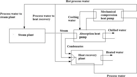
Fig.1.Block diagram of the innovative trigeneration system.
The simulation and the design of the process are carried out with ChemCad 6.3®software,not used in other literature works.An environmental analysis is also developed.The simulations allow to find performance and high-efficiency solutions for this kind of systems:a sensitivity analysis is also developed to this purpose.The economic analysis shows that the plant is economically feasible only considering economic incentives,obtained by the reduction of consumed primary energy.This process then represents an attractive technological alternative to produce power,cooling and heating simultaneously.
2.Materials and Method
2.1.Description of the trigeneration process
The innovative trigeneration process,shown in Fig.1,is composed by steam plant section,thermal recovery plant section,mechanical compression heat pump operating with R-134a and absorption heat pump using LiBr-H2O solution.The process produces power,heating and cooling simultaneously using only one source of primary energy,represented by a renewable energy source as biogas.
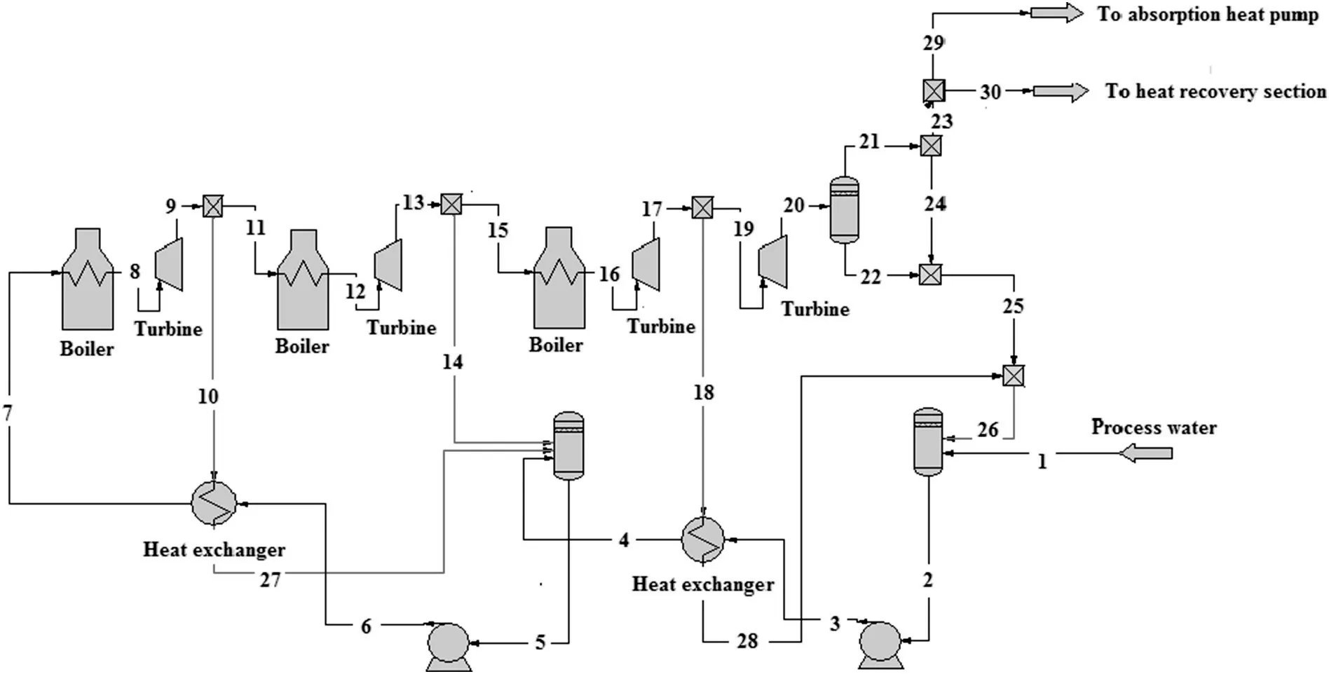
Fig.2.Process scheme of the steam plant section developed in ChemCad 6.3®environmental(for stream numbers see Table 1).

Fig.3.Process scheme of the heat recovery plant section developed in ChemCad 6.3®environmental(for stream numbers see Table 2).
In the plant,the combustion of biogas involves inside the boiler of the steam plant,providing the primary energy to the process.The steam plant section produces the electrical energy and the steam at low pressure,which is valorized because it feeds the absorption heat pump and the heat recovery plant section.The novelty of this process is to use the heat at low temperature,produced by the absorption heat pump(by the absorption and condensation processes),for a mechanical compression heat pump that receives the process water at low temperature from the heat recovery section in order to increase its temperature.The hot process water produced by the mechanical compression heat pump is partially sent to steam plant for the electrical energy production and partially feeds the heat recovery plant section for the thermal energy production.
Fig.2 shows the scheme of the steam plant section developed in ChemCad 6.3®software:it is composed of two overheating heat exchangers and four turbines[59].The regeneration is carried out by two surface heat exchangers and a mixing heat exchanger.In the boiler,biogas is combusted and has the following composition:methane equal to 59.6 wt%,carbon dioxide equal to 39.1 wt%,nitrogen equal to 0.9 wt%,oxygen equal to 0.2 wt%,sulfurized hydrogen equal to 0.2 wt%.
Fig.3 shows the process scheme of the heat recovery plant section developed in ChemCad 6.3®environmental:it consists of two heat exchangers in series,where the residual heat of the process streams is recovered[60].In the first heat exchanger that operates at higher temperature,the latent heat of the steam from the steam plant section is exchanged.In the second heat exchanger that operates at lower temperature,the heat from the hot streams of the plant is recovered.The two heat exchangers allow to have a higher temperature of the utility water:the first heat exchanger acts as a pre-heater,while the second heat exchanger acts as a condenser of the steam,providing high levels of temperature.All currents of the plant with a good heat level(the condensates from the absorption heat pump and the water heated by the compression heat pump)are sent to second heat exchanger to recover the residual heat.
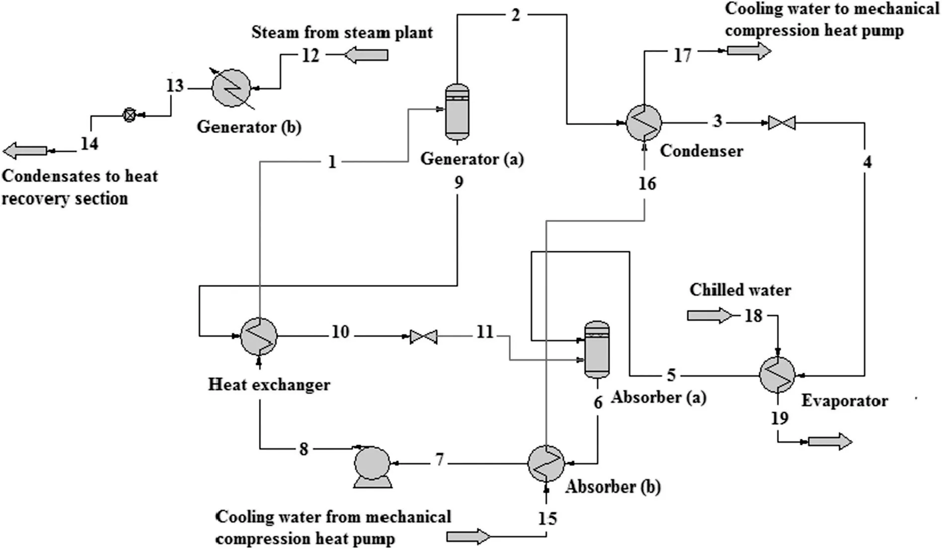
Fig.4.Process scheme of the absorption heat pump section developed in ChemCad 6.3®environmental(for stream numbers see Table 3).
Fig.4 shows the single effect absorption heat pump as modeled by Leonzio[61].The system,a simple single-effect absorption heat pump,comprises an evaporator,an absorber,a solution pump,a solution heat exchanger,a generator,a condenser,an expansion and a solution valve[62].Generator is simulated by flash and not by a heat exchanger to better simulate the separation of refrigerant and absorbent.It is divided in flash tank[Generator(a)]and heat exchanger[Generator(b)],to calculate the necessary steam for vaporization and then to drive the absorption heat pump.Absorber is divided in two parts:absorber a and absorber b.The two streams from the evaporator and the generator enter in the flash[Absorber(a)],where the heat of reaction is developed for the dilution of LiBr solution.This heat is removed in the heat exchanger[Absorber(b)].Cooling water enters in the absorber at first and then is sent to condenser,increasing the thermal level.The absorption temperature is lower than that of condensation,and therefore,it allows the better efficiency for the two exchangers.The used working fluid is the LiBr-H2Osolution,since it is not toxic,has a high enthalpy of vaporization and does not require a rectification step.Works about the study of absorption heat pump with LiBr-H2O are reported by Manu and Chandrashekar[63],Iranmanesh and Mehrabian[64],Ebrahimiet al.[65]:these investigations are mainly devoted to enhance the performances of the system or to identify the critical parameters that affect the performances.The single-effect lithium bromide-water(LiBr-H2O)chiller is a popular option for small-scale trigeneration systems,in particular for coupling to a MGT due to its low-temperature operability and possibility of recovering thermal energy from flue gases,without affecting the electric efficiency of the cycle[66].
Fig.5 shows the process scheme of the mechanical compression heat pump developed in ChemCad 6.3®environmental.The following are the main equipment of the system:compressor,evaporator,condenser and expansion valve[67].The mechanical compression heat pump recovers the heat from the absorption heat pump and increases the temperature of the process water,which is partially sent to steam plant and partially sent to heat recovery plant.The idea of this innovation is to exploit the heat that must be eliminated from the absorption heat pump,increasing the heat level of the water at the out of the heat recovery plant section.The working fluid used for the mechanical compression heat pump is R-134a.The thermodynamic properties are similar to R-12,but with a lower potential of ozone reduction.Among the other synthetized refrigerants,it has the lower environmental impact.The latent vaporization heat is high,so during the vaporization it absorbs a lot amount of heat.Many different refrigerants have been investigated in the last years due to new regulations regarding the environmental issues.Among these new widely used refrigerants,R134a represents the large demand in applications of domestic,commercial and industrial refrigeration[68].Study about the mechanical compression heat pump with R134a working fluid are developed by Yanget al.[69],Songet al.[70]and Qureschi and Zubair[71], finding that R134a is the more suitable.
The size of the trigeneration plant is set to 1 MW in order to have the economic incentives and it produces electrical,thermal and cooling power.The process is developed for industrial applications where the availability of biogas is more present.
2.2.Modeling of the trigeneration process
For the simulation of the trigeneration process a thermodynamic model is set in ChemCad 6.3®software.For the absorption heat pump,the electrolyte Non-Random Two Liquid(eNRTL)model is used to calculate the activity coefficients involved in the non-ideal vapor-liquid equilibrium and for compiling and predicting other thermodynamic data;the energy balances are calculated by the electrolyte's latent heat,as shown in Leonzio[61]for the same absorption heat pump.
For the eNRTL thermodynamic model,the excess Gibbs energy,used to calculate the activity coefficients is according the following relation(see Eq.(1))[72]:

The mathematical expression that describes the model is the following(see Eq.(2)):

whereis the unsymmetrical activity coefficient of ionic speciesiwhile the first and second terms on the right side of the considered equation are respectively the activity coefficients introduced by Pitzer-Debye-Hückel model and NRTL local composition models[73].The binary parameters of the system are expressed as αca,w,τca,w,τw,ca,where αca,wis the non-randomness parameter and has a value ranging from 0.1 to 0.5.Table 4 shows the binary interaction parameters for the system,where the subscriptsm,c,and a stand for molecule(m),cation(c),and anion(a),respectively;τm,cais the molecule-electrolyte interaction parameter while τca,mis the electrolyte-molecule interaction parameter as reported in Leonzio[61].
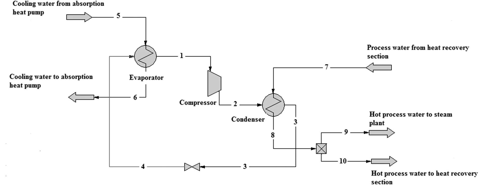
Fig.5.Process scheme of the mechanical compression heat pump developed in ChemCad 6.3®environmental(for stream numbers see Table 5).
The mathematical expression that describes the electrolyte latent heat model is according the following equation(see Eq.(3))[74]:

where:Hlis liquid enthalpy;is the heat of formation of liquid at 298.15 K;cp,lis liquid heat capacity;Hvis vapor enthalpy;Hl,bubbleis liquid enthalpy at bubble point and system pressure;Hv,bubbleis the heat of vaporization at bubble point;cp,vis the heat capacity of vapor.
The concentration of LiBr is set to 56 wt%with the minimum temperature of the cycle of 303 K(in the absorber),to avoid any problems for salt crystallization.The solubility of salt is calculated according this relation(see Eq.(4))[61]:

whereTis absolute temperature in Kelvin and the default equilibrium constant coefficients,reported in ChemCad software,for LiBr and H2O are used.For salt,the value ofA,B,C,D,Eis equal to 0;for water,the value ofA,B,C,D,andE,are respectively equal to 1.41×10⁶,-1.34×10⁸,-2.25×105,0,0.
For the other section of the plant,the Soave-Redlich-Kwong(SRK)EOS thermodynamic model is chosen:it is an accurate and simple model that is widely used in gas processing simulation[75,76].The equation of SRK model is the following(see Eq.(5)):

whereRis gas constant(8.314 J·mol-1·K-1),Tis temperature in K,bis co-volume parameter(dm3·mol-1),Vis molar volume(dm3·mol-1),ais an attractive parameter[77].
The energy balances are calculated according the latent heat model,as the following equation(see Eq.(6))[78]:

whereHlis liquid enthalpy,is the heat of liquid formation at 298.15 K andcp,lis liquid heat capacity.The simulations are carried out in steady state conditions.
3.Results and Discussion
3.1.Results of simulation and design of the trigeneration process
The simulation of the trigeneration process is carried out in ChemCad 6.3®software:the energy and material balances are obtained for each section of the plant.Tables 1-3,5 show respectively the energy and material balances for steam plant,heat recovery plant,absorption heat pump and mechanical compression heat pump of the analyzed trigeneration system.It is useful to summarize the most important flow rates and design characteristics of the different sections.
For the steam plant section,the inlet process water flow rate is equal to 3052 kg·h-1and with a temperature equal to 343 K.This section produces 852 kg·h-1of steam for the absorption heat pump,at 0.2MPa and 415 K,and 2200 kg·h-1of steam for the heat recovery plant section with the same operative conditions.The combustion heat of biogas is equal to 3280 kW,the power of turbines is 672 kW while the consumed biogas is 672 kg·h-1.
The thermal power of the heat recovery plant section is equal to 2522 kW.This section produces 31258 kg·h-1of cold process water and it is fed by 2200 kg·h-1of steam at 0.2MPa and 415 K,by 853 kg·h-1of condensates from absorption heat pump at 368 K and by 28206 kg·h-1of hot process water at 343 K.
For the absorption heat pump section the value of the coefficient of performance(C.O.P.)is equal to 0.85 with 6345 kg·h-1of LiBr solution circulating inside the system.The power of generator,evaporator,absorber and condenser are respectively equal to 559 kW,472 kW,526 kW,and 505 kW.The flow rate of the steam feed in the generator is of 852 kg·h-1(as explained at first for the steam plant section)with a pressure of 0.2MPa and with an inlet and an outlet temperature of 415 K and 369 K respectively.The evaporator uses a chilled flow rate of 101230 kg·h-1with the inlet and outlet temperature equal to 285 K and 281 Krespectively.These values are comparable with the results reported by Yanget al.[79]for an absorption heat pump integrated in a trigeneration system,where a complete sensitivity analysis is developed.
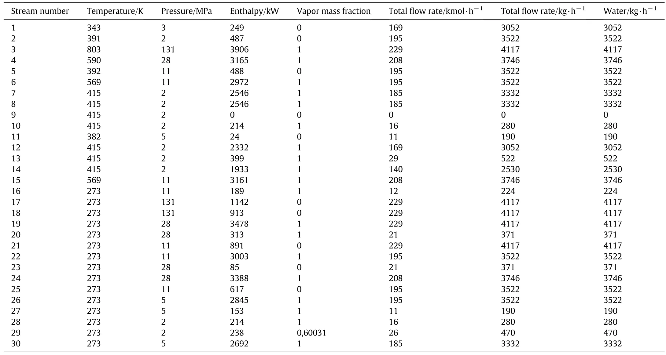
Table 1 Material and energy balances obtained by simulation in ChemCad 6.3®for the steam plant(see Fig.2)

Table 2 Material and energy balances obtained by simulation in ChemCad 6.3®for the heat recovery plant(see Fig.3)

Table 3 Material and energy balance obtained by simulation in ChemCad 6.3®for the absorption heat pump(see Fig.4)
The same design considerations are reported for the mechanic compression heat pump.The C.O.P.of the system is equal to 5,with a flowrate of R134a refrigerant equal to 22660 kg·h-1.The evaporator,condenser and compressor power are respectively equal to 1032 kW,1270 kW,and 238 kW.The cooling water used in the evaporator and from the absorption heat pump has a flowrate of 129508 kg·h-1,withan inlet and an outlet temperature equal to 305 K and 299 K respectively.The process water used in the condenser has a flow rate of 31258 kg·h-1,with an inlet and an outlet temperature of 308 K and 343 K respectively.This stream is divided at the outlet for the heat recovery plant section(with flow rate equal to 28206 kg·h-1)and for the steam plant section(with flow rate equal to 3052 kg·h-1).

Table 5 Material and energy balance obtained by simulation in ChemCad 6.3®for the mechanical compression heat pump(see Fig.5)
The energy efficiency of the system is evaluated by primary energy rate(P.E.R.),as the ratio between the required primary energy and the sum of the useful effects that the plant provides,as the following relation(see Eq.(6))[80,81]:

where theQCCHPis primary energy used for the process,QHeatingis thermal useful effect,QCoolingis cooling useful effect,andPelectricis produced electrical power.For a plant with a size equal to 1 MW,the obtained value of P.E.R.is 1.04.Table 6 summarizes the main important design conditions for the trigeneration plant.
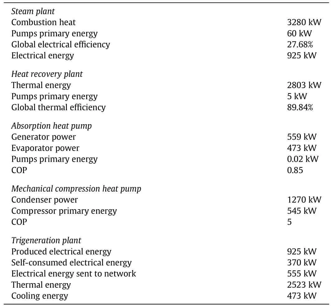
Table 6 Design characteristics for the trigeneration plant
In this evaluation,the produced electrical power is 925 kW,the produced thermal power is 2523 kW,the produced cooling power is 473 kW,while the used primary energy for the process,obtained by the combustion of biogas,is equal to 3280 kW.The low value of P.E.R.suggests that the plant work in optimal conditions exploiting the feed combustion.The electrical efficiency of the process is 27.68%,the thermal efficiency is 89,84%and the overall efficiency is 88,76%.These values are comparable with the results reported by Boukhanoufet al.[82]for a trigeneration system.In this conditions,the carbon dioxide emissions are equal to 0.27 kg·kW-1·h-1:4572 t·a-1of CO2emissions considering the operation time of 4320 t·a-1.
It is possible to compare the efficiency of the trigeneration system with a cogeneration system of the same size that produces thermal and electric power.Using the same primary energy(3280 kW)the cogeneration system produces 925 kW of electrical power and 1875 kW of thermal power.P.E.R.is equal to 1.20:the useful effect is 29%lower than the trigeneration system.Carbon dioxide emissions for the cogeneration system are equal to 0.38 kg·kW-1·h-1:the system produces a higher carbon dioxide emissions compared to trigeneration system,equal to 40%.In particular,considering the operation time of 4320 t·a-1,the plant produces 4596 t·a-1of CO2emissions.
From the obtained results,it is evident that the trigeneration system present a better exploitation of the injected fuel and a lower carbon dioxide emissions compared to cogeneration system.In trigeneration condition,the same planthas a higher performances,due to the integration of the two heat pumps.The trigeneration process is considered as highly energy-efficient because the used technologies allow to save more energy and reduce more greenhouse gas emissions than the traditional system[79].The advantages of the trigeneration systems compared to cogeneration systems are also reported by do Espirito Santo[83],Angrisaniet al.[84]and Boukhanoufet al.[82].The trigeneration process is also considered by the European Community as one of the most effective measures to both save primary energy as well as reduce greenhouse gas emissions.
3.2.Results of sensitivity analysis for the trigeneration process
A sensitivity analysis is developed to study the performance of the trigeneration plant varying some parameters as produced electric power,process water temperature and produced cooling power.Fig.6 shows P.E.R.versus the produced electric power:the effect of the electric power is positive so P.E.R.has higher values with higher values of the produced electric power.The exploitation of fuel used for the combustion decreases with the produced electric power.For lower value of the produced electric power P.E.R.has values that are lower of the unit:the amount of the useful effect is higher than the used primary energy.This fact does not mean that the process produces energy,but that the total input energy is not distributed optimally.Fig.7a shows the trend of the produced thermal energy versus the produced electrical energy:the effect is positive.Fig.7b shows the trend of the heat combustion of the steam plantversusthe produced electrical energy:the effect is positive because the higher combustion of biogas produces higher useful effect as the electrical energy.

Fig.6.Trend of P.E.R.versus produced electric power for the trigeneration system.
Fig.8 shows the effect of cooling capacity on P.E.R.of the system.To this purpose,temperature of the process water that is sent to steam plant and to heat recovery plant is changed.The operative conditions of mechanical compression heat pump are then changed.The aim of this analysis is to evaluate the influence of the mechanical compression heat pump on the efficiency of the trigeneration system.The analysis is carried out at the fixed amount of steam for the heat recovery plant and at the fixed produced electrical energy.As shown in Fig.8,P.E.R.varies in linear way with the process water temperature and the effect is positive.However,low temperature of the process water determines conditions not optimal at the heat exchanger of heat recovery plant.For this reason,the optimal temperature is equal to 343 K,with a compatible value of P.E.R.for the trigeneration system.Fig.9a,9b and 9c shows the discussed considerations.

Fig.7.Analysis of produced electrical energy in the trigeneration system:a)trend of produced thermal energy versus produced electrical energy;b)trend of produced electrical energy versus the heat combustion of biogas.
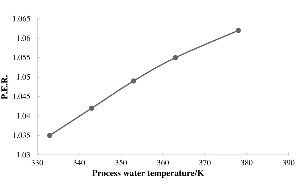
Fig.8.Trend of P.E.R.in trigeneration system versus process water temperature.
Plot in Fig.9a is a consequence of the behavior of the mechanical compression heat pump varying process water temperature.The influence of process water temperature is positive on the outlet pressure of compressor and negative on C.O.P.Increasing process water temperature,the compression heat pump works with higher pressure of cycle,increasing the power of the compressor and decreasing the C.O.P.Also,a higher process water temperature determines a higher thermal power on the evaporator of mechanical heat pump as shown in Fig.9a and a higher cooling capacity on absorption heat pump.In addition,the required heat for the generator increases,because the C.O.P.of absorption heat pump is fixed.

Fig.9.Analysis of the system varying the process water temperature of the trigeneration system:a)trend of produced thermal energy versus process water temperature;b)trend of electrical energy versus process water temperature;c)trend of cooling power versus process water temperature.
A further analysis must to study the trend of the consumed electrical energy and the self-produced energy as a function of process water temperature,as in Fig.9b.With a higher process water temperature,the amount of the self-produced energy increases because increases the consumption of the compressor in the heat pump while the amount of the electrical energy sent to the network decreases.It is evident that if the amount of the self-produced energy is higher,the convenience of the process decreases.As the cooling capacity increases,the plant produces the same quantity of electrical energy but consumes higher electrical energy:the expenditure due to the higher refrigerant capacity is paid by the lower production of electrical energy.Temperature process water has also a positive effect on the produced cooling power as shown in Fig.9c.
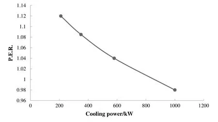
Fig.10.Trend of P.E.R.for the trigeneration system versus cooling capacity.
Fig.10 shows the efficiency of the trigeneration system varying cooling power.The amount of the refrigerant in the absorption heat pump is varied and the effect on the efficiency of the system is evaluated.P.E.R.decreases with higher cooling power,so the exploitation of the fuels is better.The produced electrical power is constant,but thermal power and cooling power increase.The increase of thermal power is due to the increase of the heat removed by the absorption heat pump with the increase of the cooling capacity.This heat can be used in the mechanical compression heat pump that improve its quality,increasing temperature.The negative effect associated with the increase of the refrigerant capacity is related to higher compressor consumption that reduces the amount of electrical power that can be sent into the network.
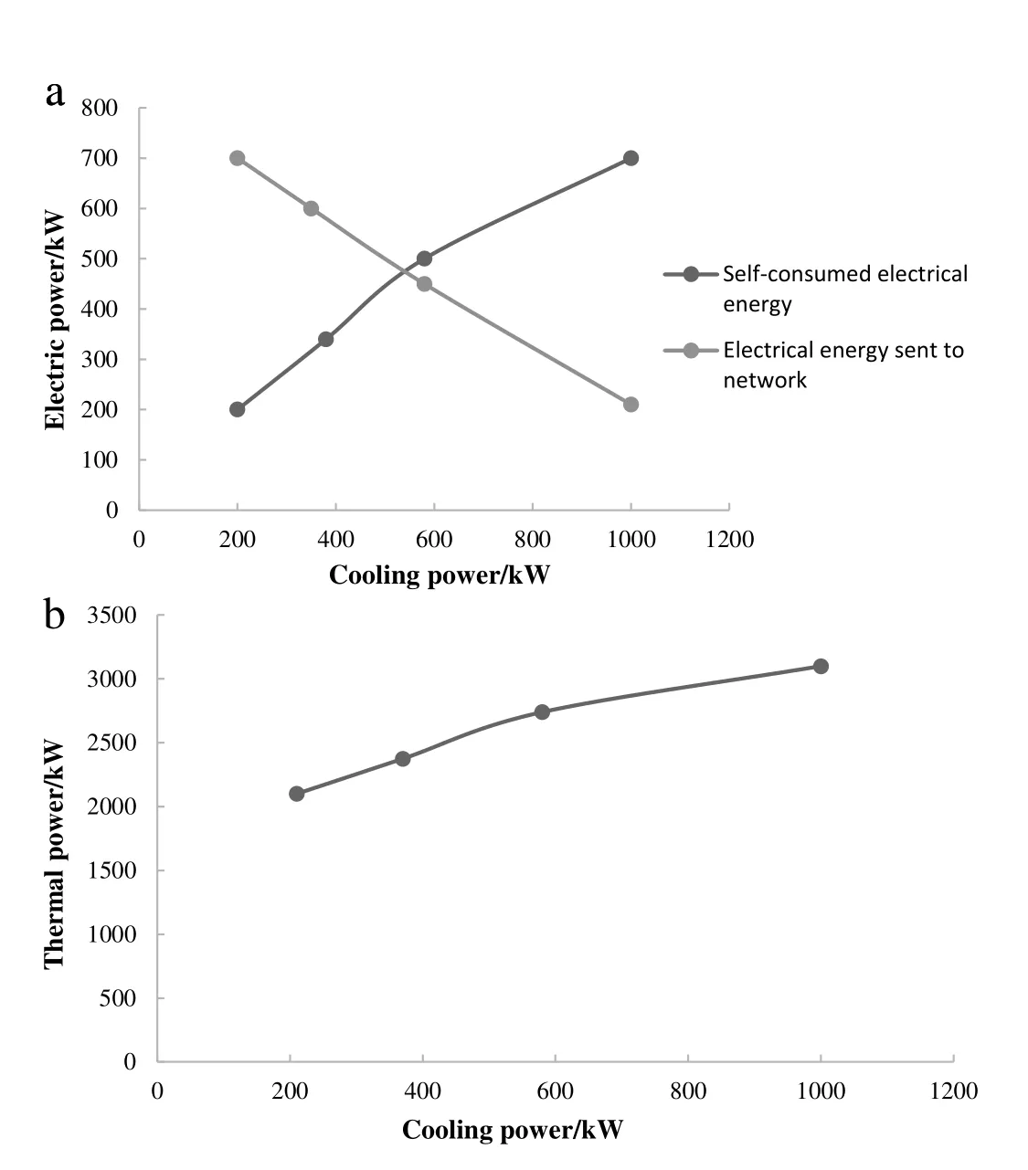
Fig.11.Analysis of the system varying cooling capacity:a)trend of electrical energy versus cooling capacity;b)trend of produced thermal energy versus cooling capacity.
Cooling power influences the mechanical compression heat pump:this parameter has a positive effect on compressor power.C.O.P.of the heat pump is the same,but varies the amount of the refrigerant because it exchanges a higher thermal load in the evaporator.Influences are then on the produced and self-consumed electrical energy.Cooling power has a negative effect on the self-consumed electrical energy while has a positive effect on the produced electrical energy,as shown in Fig.11a.In fact,the higher compressor power in the heat pump increases the self-consumed electrical energy and decreases the amount of energy that is sent to network.The heat recovery plant section with the increase of cooling capacity receives a lower amount of steam,because a higher amount is sent to the absorption heat pump,but increasing the cooling capacity the potential of the heat pump increases,so a higher amount of water is sent to plant,after being heated in the heat pump.The resulting trend is an overall increase in the thermal power as increasing the cooling power,as shown in Fig.11b.This shows that the effect of the increase in water flow rate from the heat pump is greater than the decrease in the amount of steam sent to the heat recovery plant section(Figs.11a and 11b).
3.3.Results of economic analysis for the trigeneration process
An economic analysis is developed for the trigeneration plant with the aim to evaluate the economic feasibility.An estimation of the equipment costs is calculated from the Matche software,according their size.The economic analysis in this research is carried out according Seideret al.[85]with results shown in Table 6,where total capital investment,total production costs and total revenues are reported.The total costs of the equipment are equal to 3437000 EUR[86].Service costs are the 11%of the total equipment costs,engineering costs are the 18%of the direct costs(the sum of the total costs of equipment and service costs)[85].The cost of the land is the 2%of total depreciable cost[85].Total depreciable cost is considered as the sum of direct costs and engineering costs.Total capital investment is equal to 5056200 EUR.Total production costs are calculated considering 30 labors,while other costs are calculated according Seideret al.[85].Electricity,thermal and cooling costs are respectivelyequal to 0.28 EUR⋅kW-1·h-1,0.12 EUR·kW-1·h-1,0.25 EUR·kW--1·h-1[87]:the revenues for the production of these energies are obtained considering an operation time of the plant equal to 4320 h and are equal to 2938000 EUR(Table 7).

Table 7 Economic analysis of the trigeneration system
Economic incentives are obtained by the trigeneration system due to primary energy saving,using the absorption heat pump,the mechanical compression heat pump and the steamplant(this plant works in condition of cogeneration with high efficiency with a Primary Energy Saving equal to 19%).The economic incentives are known as with certificates(WhC).The number of the obtained white certificates,corresponds to the integral net saving of primary energy,equal to the product of the net savings and a coefficient of durability,classified by class of action and function of the technical life,the useful life of the plant and a decay rate of savings.With this last coefficient,the energy saving is amortized over the entire technical life of the plant.The net saving is obtained multiplying the gross saving(that is the primary energy that heat pumps can have compared to the use of an industrial boiler),with a coefficient of additionality.With the latter,the savings of a situation of high efficiency are compared to a baseline situation(the average of the market).The obtained white certificates are of second type(the value is equal to 102.18 EUR·tep-1,where tep is for ton equivalent petroleum)since the heat pumps allow to have a primary energy saving by reducing the consumption of naturalgas.Multiplying the number of obtained white certificates for their value it is possible to have the economic incentives,obtained through the use of heat pumps.
The three systems allow to save 1914 tep·a-1:the absorption heat pump saves 275 tep·a-1,the mechanical compression heat pump saves 1081 tep·a-1,the steam plant saves 558 tep·a-1.Considering a coefficient of additionality equal to 1 the gross saving primary energy and the net saving primary energy correspond to 1914 tep·a-1.For a coefficient of durability of 3.36 the net saving integral primary energy and so the white certificates are equal to 6431 tep·a-1.The heat pumps allow to receive 6431 tep·a-1corresponding to 658000 EUR·a-1.
The Energy Savings Certificates(E.S.C.)or white certificates defined by the program law of July 13th 2005 establishing the policies to promote energy efficiency,is currently considered by several countries in the EU.The basic idea of this policy is that specific energy saving targets are set for energy suppliers or energy distributors,so energy efficiency measures must to be reached within a defined period.The fulfillment is acknowledged by means of white certificates.Energy suppliers or distributors,can fulfill their targets or can sell their unused energy efficiency equivalents in the form of WhC to suppliers or distributors which have not fulfill their targets[88].Different types of certificates are present for energy saving projects related to electrical energy(Type I),related to gas(Type II),and related to other fuels(Type III)[89].
After calculation of economic incentives,an economic analysis of the plant is carried out to verify the economic feasible of the process.
Results of economic analysis show that the plant is not economically feasible without consider economic incentives.In fact,the value of Net Present Value(N.P.V.)is negative and equalto-572000 EUR with a payback period(P.B.P.)of 14 years.However,white certificates make the plant economic feasible:N.P.V.is positive and equal to 371000 EUR and P.B.P.is equal to 4 years.The feasibility of the plant is comparable with other works reported in literature as Alcantara[90].
4.Conclusions
A trigeneration process can simultaneously produce electricity,cooling and thermal energies from one input energy or recovering the heat discharged from the power generation.The system allows to save more energies and to reduce greenhouse emissions,compared to traditional system,as cogeneration system or other process that produce separately this energy vectors.
A trigeneration system for the production of electricity,cooling and heating has been analyzed in this research.An innovative scheme integrating an absorption heat pump and a mechanical compression heat pump is developed.The low temperature heat produced by absorption chiller is sent and valorized in a second compression heat pump,that receives process water at lower temperature from the heat recovery plant and brings it to higher temperatures.The trigeneration system is composed by absorption heat pump,mechanical compression heat pump,steam plant and thermal recovery heat plant.A design and an analysis simulation are carried out in ChemCad 6.3®software.In literature,works about the modeling of trigeneration system through ChemCad 6.3®are not present.The plant produces 925 kW of electrical power,2523 kW of thermal power and 473 kW of cooling power.Biogas is used as fuel producing by combustion 3280 kW of power.Biogas is a source of renewable energy at relatively low cost.An economic analysis is also developed to evaluate the feasibility of the plant.Results show that the plant is economic feasible only considering economic incentives,(white certificates)obtained by primary energy save,using the absorption heat pump and the steam plant.A sensitivity analysis is carried out in order to evaluate the efficiency of the trigeneration system at different factors,as cooling capacity,produced electrical energy and process water temperature.Cooling capacity has a negative effect on P.E.R.,process water temperature and produced electric power have a positive effect on PER.The analyzed trigeneration scheme has energetic and environmental advantages compared to cogeneration system that uses the same amount of biogas as fuels.In fact,the cogeneration system produces 925 kW of electrical power and 1875 kW of thermal power:P.E.R.is equal to 1.20 and the useful effect is 29%lower compared to trigeneration system.Also,the cogeneration system produced 4596 t·a-1of carbon dioxide,that is higher than the trigeneration system that produces 4572 t·a-1of carbon dioxide.
Future works should optimize the process considering costs and energetic efficiency,as two objective functions.
Acknowledgments
The author of the study would like to thank the European Commission for funding this work.
[1]M.S.Rocha,R.Andreos,J.R.Simões-Moreira,Performance tests of two small trigeneration pilot plants,Appl.Therm.Eng.41(2012)84-91.
[2]IEA—International Energy Agency,Key world energy statisticsAvailableat:www.iea.org 2012,Accessed date:29 June 2013.
[3]D.B.do Espirito Santo,W.L.R.Gallo,Utilizing primary energy savings and exergy destruction to compare centralized thermal plants and cogeneration/trigeneration systems,Energy120(2017)785-795.
[4]Y.Y.Jing,H.Bai,J.J.Wang,A fuzzy multi-criteria decision-making model for CCHP systems driven by different energy sources,Energy Policy42(2012)286-296.
[5]M.Carvalho,L.M.Serra,M.A.Lozano,Optimal synthesis of trigeneration systems subject to environmental constraints,Energy36(2011)3779-3790.
[6]N.Fumo,P.J.Mago,K.Jacobs,Design considerations for combined cooling,heating,and power systems at altitude,Energy Convers.Manag.52(2011)1459-1469.
[7]S.G.Tichi,M.M.Ardehali,M.E.Nazari,Examination of energy price policies in Iran for optimal configuration of CHP and CCHP systems based on particle swarm optimization algorithm,Energy Policy38(2010)6240-6250.
[8]E.Cetinkaya,Experimental investigation and modeling of integrated tri-generation systems,Doctor of Philosophy in the Faculty of Engineering and Applied Science Mechanical Engineering Program University of Ontario Institute of Technology,2013.
[9]E.Cardona,A.Piacentino,A measurement methodology for monitoring CHCP pilot plant for an office building,Energy Build.35(2003)919-925.
[10]G.Angrisani,A.Rosato,C.Roselli,M.Sasso,S.Sibilio,Experimental results of a microtrigeneration installation,Appl.Therm.Eng.38(2012)78-90.
[11]O.Balli,H.Aras,A.Hepbasli,Thermodynamic and thermos-economic analyses of a trigeneration(TRIGEN)system with a gas-diesel engine:Part II—An application,Energy Convers.Manag.51(2010)2260-2271.
[12]H.Ghaebi,M.Amidpour,S.Karimkashi,O.Rezayan,Energy,exergy and thermoeconomic analysis of a combined cooling,heating and power(CCHP)system with gas turbine prime mover,Int.J.Energy Res.35(2011)697-709.
[13]M.Moya,J.C.Bruno,P.Eguia,E.Torres,I.Zamora,A.Coronas,Performance analysis of a trigeneration system based on a micro gas turbine and an air-cooled,indirect fired,ammonia water absorption chiller,Appl.Energy88(2011)4424-4440.
[14]M.Badami,M.Ferrero,A.Portoraro,Experimental tests of a small-scale micro-turbine with a liquid desiccant cooling system,Int.J.Energy Res.37(2013)1069-1078.
[15]M.F.B.Basrawi,T.Yamada,K.Nakashini,H.Katsumata,Analysis of the performance of biogas-fuelled micro gas turbine cogeneration system(MGT-CGSs)in middle and small scale sewage treatment plants:comparison of performance and optimization of MGTs with various electrical power outputs,Energy30(2012)291-304.
[16]Z.Yu,J.Han,X.Cao,W.Chen,B.Zhang,Analysis of total energy system based on solid oxide fuel cell for combined cooling and power applications,Int.J.Hydrog.Energy35(2010)2703-2707.
[17]F.A.Al-Sulaiman,F.Hamdullahpur,I.Dincer,Trigeneration:A comprehensive review based on prime movers,Int.J.Energy Res.35(2011)233-258.
[18]X.Q.Kong,R.Z.Wang,X.H.Huang,Energy efficiency and economic feasibility of CCHP driven by stirling engine,Energy Convers.Manag.45(2004)1433-1442.
[19]A.Knizley,P.J.Mago,Evaluation of combined heat and power(CHP)systems performance with dual power generation units for different building configurations,Int.J.Energy Res.37(2013)1529-1538.
[20]W.B.Buescher,Trigeneration:Principles,Feasibility,and Energy Price Sensitivity,North Carolina State Univ,Raleigh,2011.
[21]Q.A.Acton,Issues in Engineering Research and Application,2013 ed.Scholarly Editions,Atlanta,GA,2013.
[22]A.Thumann,Plant Engineers and Managers Guide to Energy Conservation,The Fairmont Press,Lilburn,GA,2010.
[23]A.Ziębik,K.Hoinka,Energy Systems of Complex Buildings:Green Energy and Technology,Springer-Verlag,London,UK,2012.
[24]M.M.El-Halwagi,Sustainable Design through Process Integration:Fundamentals and Applications to Industrial Pollution Prevention,Resource Conservation,and Pro fitability Enhancement,Elsevier,Oxford,UK,2011.
[25]S.de Oliveira Jr.,Exergy:Production,Cost and Renewability,Springer-Verlag,London,UK,2012.
[26]M.Jradi,S.Riffat,Trigeneration systems:energy policies,prime movers,cooling technologies,configurations and operation strategies,Renew.Sustain.Energy Rev.32(2014)396-415.
[27]S.Campanari,L.Boncompagni,E.Macchi,Microturbines and trigeneration:optimization strategies and multiple engine configuration effects,J.Eng.Gas Turbines Power126(2004)92-101.
[28]J.C.Bruno,A.Valero,A.Coronas,Performance analysis of combined microgas turbines and gas fired water/LiBr absorption chillers with post-combustion,Appl.Therm.Eng.25(2005)87-99.
[29]Y.Hwang,Potential energy benefits of integrated refrigeration system with microturbine and absorption chiller,Int.J.Refrig.27(2004)816-829.
[30]D.B.de Espirito Santo,An energy and exergy analysis of a high-efficiency engine trigeneration system for a hospital:A case study methodology based on annual energy demand profiles,Energy Build.76(2014)185-198.
[31]S.Chao,A.D.Smith,P.Mago,Combined cooling,heating and power:a review of performance improvement and optimization,Appl.Energy136(2014)168-185.
[32]E.Jannelli,E.Minutillo,R.Cozzolino,G.Falcucci,Thermodynamic performance assessment of a small size CCHP(combined cooling heating and power)system with numerical models,Energy65(2014)240-249.
[33]S.A.Tassou,I.Chaer,N.Suguartha,T.Ge,D.Marriott,Application of trigeneration systems to the food retail industry,Energy Convers.Manag.48(2007)2988-2995.
[34]M.Ameri,A.Behbahaninia,A.A.Tanha,Thermodynamic analysis of a tri-generation system based on micro-gas turbine with a steam ejector refrigeration system,Energy35(2010)2203-2209.
[35]F.Meunier,C.Chevalier,Environmental assessment of biogas co-or trigeneration units by life cycle analysis methodology,Appl.Therm.Eng.25(2005)3025-3041.
[36]F.Meunier,Co-and tri-generation contribution to climate change control,Appl.Therm.Eng.22(2002)703-718.
[37]M.Carvalho,M.Lozano,L.Serra,Multicriteria synthesis of trigeneration systems considering economic and environmental aspects,Appl.Energy91(2012)245-254.
[38]P.Mancarella,MES(multi-energy systems):An overview of concepts and evaluation models,Energy1(2013)1-17.
[39]G.Temir,D.Bilge,G.Emanet,An application of trigeneration and its economic analysis,Energy Sources26(2004)857-867.
[40]U.Eicker,Biomass trigeneration with decentral cooling by district heating networks,Proceedings of 2nd Polygeneration Conference,Tarragona,2011.
[41]J.C.Bruno,V.Ortega-López,A.Coronas,Integration of absorption cooling systems into micro gas turbine trigeneration systems using biogas:Case study of a sewage treatment plant,Appl.Energy86(2009)837-847.
[42]Y.Huang,Y.D.Wang,S.Rezvani,D.R.McIlveen-Wright,M.Anderson,N.J.Hewitt,Biomass fuelled trigeneration system in selected buildings,Energy Convers.Manag.52(2011)2448-2454.
[43]J.J.Wang,K.Yang,Z.L.Xu,C.Fu,Energy and exergy analyses of an integrated CCHP system with biomass air gasification,Appl.Energy142(2015)317-327.
[44]D.Maraver,A.Sin,F.Sebastián,J.Royo,Environmental assessment of CCHP(combined cooling heating and power)systems based on biomass combustion in comparison to conventional generation,Energy57(2013)17-23.
[45]P.Balcombe,D.Rigby,A.Azapagic,Environmental impacts of microgeneration:Integrating solar PV,stirling engine CHP and battery storage,Appl.Energy139(2015)245-259.
[46]J.Wang,Y.Yang,T.Mao,J.Sui,H.Jin,Life cycle assessment(LCA)optimization of solar-assisted hybrid CCHP system,Appl.Energy146(2015)38-52.
[47]P.Mancarella,G.Chicco,Assessment of the greenhouse gas emissions from cogeneration and trigeneration systems.Part II:Analysis techniques and application cases,Energy33(2008)418-430.
[48]D.Xu,Q.Liu,J.Lei,et al.,Performance of a combined cooling heating and power system with mid-and-low temperature solar thermal energy and methanol decomposition integration,Energy Convers.Manag.102(2015)17-25.
[49]F.A.Al-Sulaiman,Thermodynamic Modeling and Thermoeconomic Optimization of Integrated Trigeneration Plants Using Organic Rankine Cycles(Ph.D.dissertation)Dept.of Mech.Eng.,Univ.of Waterloo,Waterloo,ON,2010.
[50]K.J.Chua,W.M.Yang,T.Z.Wong,C.A.Ho,Integrating renewable energy technologies to support building trigeneration—A multi-criteria analysis,Renew.Energy41(2012)358-367.
[51]W.Gazda,W.Stanek,Energy and environmental assessment of integrated biogas trigeneration and photovoltaic plant as more sustainable industrial system,Appl.Energy169(2016)138-149.
[52]A.Buonomano,F.Calise,A.Palombo,M.Vicidomini,Energy and economic analysis of geothermal-solar trigeneration systems:A case study for a hotel building in ischia,Appl.Energy138(2015)224-241.
[53]A.Arteconi,C.Brandoni,F.Polonara,Distributed generation and trigeneration:Energy saving opportunities in Italian supermarket sector,Appl.Therm.Eng.29(2009)1735-1743.
[54]K.Cacua,L.O.Villallba,B.Herrera,A.Gallego,Experimental evaluation of a dieselbiogas dual fuel engine operated on micro-trigeneration system for power,drying and cooling,Appl.Therm.Eng.100(2016)762-767.
[55]X.Zhang,H.Li,L.Liu,R.Zeng,G.Zhang,Analysis of trigeneration system taking solar energy and biomass as co-feeds,Energy Convers.Manag.122(2016)74-84.
[56]H.Li,X.Zhang,L.Liu,R.Zeng,G.Zhang,Exergy and environmental assessment of a novel trigeneration system taking biomass and solar energy as co-feeds,Appl.Therm.Eng.104(2016)697-706.
[57]O.J.Shariatzadeh,A.H.Refahi,M.Rahmani,S.S.Abolhassani,Economic optimization and thermodynamics modelling of SOFC trigeneration system fed by biogas,Energy Convers.Manag.105(2015)772-781.
[58]J.Wang,T.Mao,J.Sui,et al.,Modeling and performance analysis of CCHP(combined cooling,heating and power)system based on co- firing of natural gas and biomass gasification gas,Energy93(2015)801-815.
[59]C.Celis,G.R.S.Pinto,T.Teixeira,É.Xavier,A steam turbine dynamic model for full scope power plant simulators,Appl.Therm.Eng.120(2017)593-602.
[60]G.V.P.Varma,T.Srinivas,Power generation from low temperature heat recovery,Renew.Sustain.Energy Rev.75(2017)402-414.
[61]G.Leonzio,Mathematical model of absorption and hybrid heat pump,Chin.J.Chem.Eng.25(10)(2017)1492-1504.
[62]P.Chatzitakis,B.Dawoud,An alternative approach towards absorption heat pump working pair screening,Renew.Energy110(2017)47-58.
[63]S.Manu,T.K.Chandrashekar,A simulation study on performance evaluation of single-stage LiBr-H2O vapor absorption heat pump for chip cooling,Int.J.Sustain.Built Environ.5(2016)370-386.
[64]A.Iranmanesh,M.A.Mehrabian,Thermodynamic modelling of a double-effect LiBr-H2O absorption refrigeration cycle,Heat Mass Transf.48(2012)2113-2123.
[65]K.Ebrahimi,G.F.Jones Fleischer,A.S.Fleischer,Thermo-economic analysis of steady state waste heat recovery in data centers using absorption refrigeration,Appl.Energy139(2015)384-397.
[66]A.M.Pantaleo,S.M.Camporeale,C.N.Markides,G.S.Mugnozza,N.Shah,Energy performance and thermo-economic assessment of a microturbine-based dual-fuel gas-biomass trigeneration system,Energy Procedia105(2017)764-772.
[67]M.Saikawa,S.Koyama,Thermodynamic analysis of vapor compression heat pump cycle for tap water heating and development of CO2heat pump water heater for residential use,Appl.Therm.Eng.106(2016)1236-1243.
[68]F.Billiard,New trends in refrigerating equipment and refrigerants,Proceedings of Xth European Conference on Technological Innovations in Air Conditioning and Refrigeration Industry,2003.
[69]D.Yang,Y.Song,F.Cao,L.Jin,X.Wang,Theoretical and experimental investigation of a combined R134a and transcritical CO2heat pump for space heating,Int.J.Refrig.72(2016)156-170.
[70]Y.Song,D.Li,D.Yang,L.Jin,F.Cao,X.Wang,Performance comparison between the combined R134a/CO2heat pump and cascade R134a/CO2,Int.J.Refrig.74(2017)592-605.
[71]B.A.Qureschi,S.M.Zubair,The effect of refrigerant combinations on performance of a vapor compression system with dedicated mechanical subcooling,Int.J.Refrig.35(2012)47-57.
[72]A.Haghtalab,J.H.Vera,A nonrandom factor model for the excess Gibbs energy of electrolyte solutions,AICHE J.34(1988)803-813.
[73]J.M.Prausnitz,R.N.Lichtenthaler,E.G.de Azevedo,Molecular Thermodynamics of Fluid Phase Equilibria,third ed.Prentice Hall,New Jersey,1999 537-556.
[74]G.Leonzio,Recovery of metal sulphates and hydrochloric acid from spent pickling liquors,J.Clean.Prod.129(2016)417-426.
[75]J.Gao,Y.Wang,Y.Ping,D.Hu,G.Xu,F.Gu,F.Su,A thermodynamic analysis of methanation reactions of carbon oxides for the production of synthetic natural gas,RSC Adv.2(2012)2358-2368.
[76]M.K.Nikoo,N.Amin,Thermodynamic analysis of carbon dioxide reforming of methane in view of solid carbon formation,Fuel Process.Technol.92(2011)678-691.
[77]C.Lundstrøm,M.L.Michelsen,G.M.Kontogeorgis,K.S.Pedersen,H.Sørensen,Comparison of the SRK and CPA equations of state for physical properties of water and methanol,Fluid Phase Equilib.247(2006)149-157.
[78]J.E.Edwards,Process Modelling Selection of Thermodynamic Methods,P&I Design Ltd.,2001 available on www.pidesign.co.uk.
[79]M.Yang,S.Y.Lee,J.T.Chung,Y.T.Kang,High efficiency H2O/LiBr double effect absorption cycles with multi-heat sources for tri-generation application,Appl.Energy187(2017)243-254.
[80]V.Havelsky,Energetic efficiency of cogeneration system for combined heat,cold and power production,Int.J.Refrig.22(1999)479-485.
[81]F.Ziegler,P.Riesch,A Review with Regard to Energetic Efficiency:Absorption Cycle,Heat Recovery Sist CHP,13,1993 147-159.
[82]R.Boukhanouf,J.Godefroy,S.B.Riffat,M.Worall,Design and optimization of a small scale tri-generation system,Int.J.Low Carbon Technol.1(2001)32-43.
[83]D.B.do Espirito Santo,An energy and exergy analysis of a high efficiency engine trigeneration system for a hospital:A case study methodology based on annual energy demand profiles,Energ.Buildings76(2014)185-198.
[84]G.Angrisani,A.Akisawa,E.Marrasso,C.Roselli,M.Sasso,Performance assessment of cogeneration and trigeneration systems for small scale applications,Energy Convers.Manag.125(2016)194-208.
[85]W.D.Seider,J.D.Seader,D.R.Lewin,Product&Process Design Principles,Synthesis,Analysis and Evaluation,II edition Wiley,New York,2004.
[86]R.Turton,R.C.Bailie,W.B.Whiting,J.A.Shaeiwitz,D.Bhattacharyya,Analysis Synthesis and Design of Chemical Processes,Fourth edition Prentice Hall,2012.
[87]M.Shelar,G.N.Kulkarni,Thermodynamic and economic analysis of diesel engine based trigeneration system for Indian hotel,Sustain.Energy Technol.Assess.13(2016)60-67.
[88]A.Afshari,L.Friedrich,Aproposalto introduce tradable energy savings certificates in the emirate of Abu Dhabi,Renew.Sustain.Energy Rev.55(2016)1342-1351.
[89]A.Petrella,A.Sapio,Assessing the impact of forward trading,retail liberalization,and white certificates on the Italian wholesale electricity prices,Energy Policy40(2012)307-317.
[90]A.Alcantara,Energetic and economic evaluation of the dimensioning of cogeneration and trigeneration plant.Available on https://fenix.tecnico.ulisboa.pt/downloadFile/395144977784/resumo.pdf 2012.
 Chinese Journal of Chemical Engineering2018年5期
- Chinese Journal of Chemical Engineering的其它文章
- Bioregeneration of spent activated carbon:Review of key factors and recent mathematical models of kinetics
- CFD simulations of quenching process for partial oxidation of methane:Comparison of jet-in-cross- flow and impinging flow configurations☆
- Quantifying growth and breakage of agglomerates in fluid-particle flow using discrete particle method☆
- Coupling simulation of fluid structure interaction in the stirred vessel with a pitched blade turbine☆
- An integrated model for predicting the flame propagation in crimped ribbon flame arresters☆
- Assessment of k-ε models using tetrahedral grids to describe the turbulent flow field of a PBT impeller and validation through the PIV technique
