基于抗差自适应Kalman滤波的车辆定位新方法
贾 勇,李岁劳,时文涛,秦永元
(1. 西北工业大学 自动化学院,西安 710129;2. 西安飞行自动控制研究所,西安 710065)
With such advantages as independence, good invisibility and strong anti-interference, the inertial navigation system (INS) is widely used in the fields of aviation,aerospace, marine, land navigation and other fields.However, it has the shortage that the navigation error accumulates with time, in which the constant errors of the inertial sensors are the main error sources[1]. The rotation modulation technology has the characteristic of error self-compensation. By periodically rotating the inertial sensors, it can eliminate the influence of the constant errors of inertial sensors on the navigation accuracy to improve the performance of INS. The researches on laser gyroscope inertial navigation system and fiber optic gyroscope inertial navigation system based on rotation modulation technology have been widely made in many countries, and those systems have been applied in many high precision navigation fields[2-3].In recent years, with the increase of the accuracy of MEMS inertial sensors, MEMS-RMINS, which combines the rotation modulation technology with MEMS inertial sensors, has begun to attract the attention of many research institutions, and some research results have been applied to the actual work[4-10].
In the existing researches of MEMS-RMINS with MEMS inertial sensors: Wang’s [7] discusses the system scheme and test results in detail; the error suppression effect under different rotating axes and parameter calibration results are analyzed in [8] and [9]; Du’s [10]combines MEMS rotation modulation inertial navigation system with GPS, and analyzes the navigation results when GPS works and fails. The above MEMS- RMINSs have the disadvantage that they are too expen- sive to be used in civilian areas. Moreover, [8]-[10] just place the MEMS inertial measurement unit (IMU) on the rotation mechanism which does not meet the requirement of miniaturization, and the navigation time is too long which makes the error extremely large. Because the road condition and the wheel state are complex in the actual work, the scheme of [6] which uses the wheel’s rotation to improve navigation accuracy is not suitable.
Due to low positioning accuracy, the pure MEMSINS cannot be used alone for a long time. Therefore, the existing vehicle positioning systems are implemented on the basis of GPS/MEMS-INS integrated navigation or by introducing the kinematic constraint (KC)[10-11]. Because the GPS signal is easily disturbed and the KC condition is not strictly white noise, the method adopted by [10]-[11] is not perfect. At the same time, the robust adaptive Kalman filter is used to improve the positioning accuracy of the system[12-13], but is not used in MEMS-RMINS.
Therefore, on the basis of the existing research, the low-cost and miniaturized MEMS-RMINS integrates with the KC to form a complete vehicle positioning method in this work by adopting the RAKF. Firstly,rotation modulation technology and kinematic constraint are introduced and analyzed; then, the new vehicle positionning method’s mathematical model, the whitening of colored noise, and RAKF algorithm are derived in detail;at the same time, combined with the experimental results,the detailed analysis of the vehicle positioning method is carried out; finally, this paper draws a conclusion.
1 Rotation modulation technology
As shown in Fig.1, MEMS rotation modulation inertial navigation system consists of MEMS-IMU,rotation mechanism (including rotation platform, DC torque motor, photoelectric encoder, and connecting piece)and control calculation system. The MEMS-IMU is fixed on the rotation mechanism, and the sensors error is compensated automatically as the rotation mechanism rotates periodically. In this system, MEMS-IMU uses ADIS16445 whose performance is shown in Tab.1.
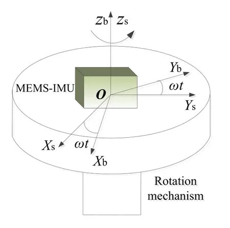
Fig.1 System structure of single-axis RMINS
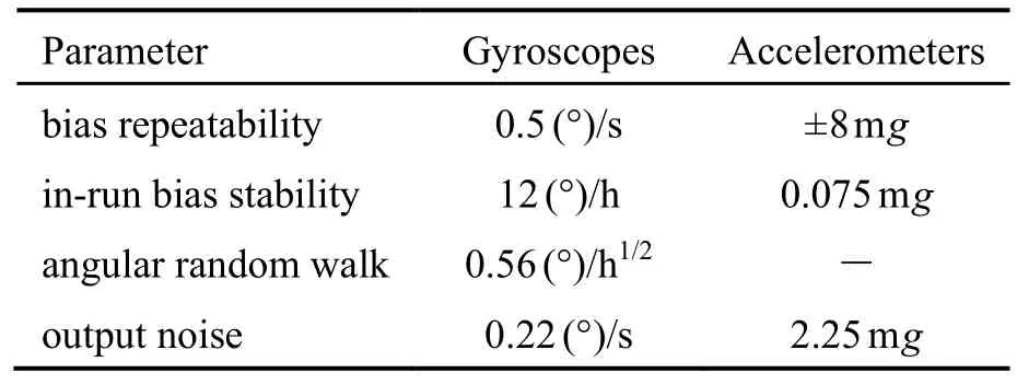
Tab.1 MEMS-IMU performance
To facilitate the analysis of rotational modulation technology, the following definitions are given: s-frame is the rotation coordinate system; b-frame is the carrier coordinate system; n-frame (ENUframe) is the navigation coordinate system which is the local East-North-Upward (ENU) coordinate system; and i-frame is the inertial coordinate system.
Supposing that s-frame coincides with b-frame in the initial time, the rotation mechanism rotates continuously in the vertical direction at constant angular speedω,then the transformation matrixat timetbetween s-frame and b-frame can be expressed as:

Supposing that b-frame coincides with n-frame for simplicity to analysis problem, namely,it can be obtained through (1) that the error form of the gyroscope constant drift of MEMS-IMU in n-frame at timetis

In (2), If there is no rotation modulation,and the integral result ofwhich grows linearly with time. After introducing the rotation modulation technology, the mean values ofare zero during every rotation period, so the mean value of the equivalent gyroscope drift error caused byis zero. The attitude no longer diverges with time which becomes periodic sine form, and the corresponding positionning accuracy is improved greatly. This is the basic principle and function of rotation modulation technology.
Aiming at the MEMS rotation modulation inertial navigation system, the angle modulation algorithm is adopted to implement navigation calculation[3], and the corresponding differential equations are as follows:
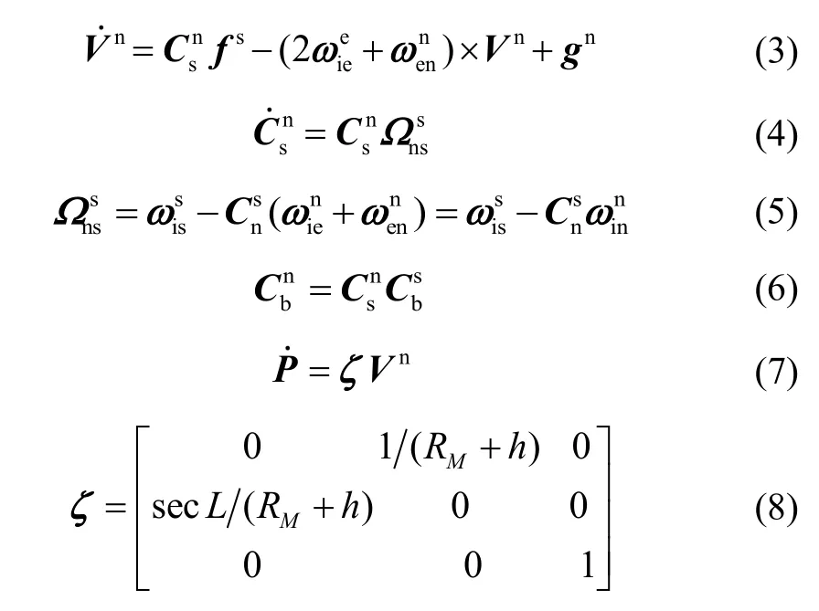
Due to the introduction of the rotation modulation technology, the corresponding error equations will also change accordingly. For actual MEMS rotation modulation inertial navigation system, there are gyroscope driftsaccelerometer biasesand angle error δθof photoelectric encoder, and on the other hand, there are error matrixμ,Ф,χ, δV, δPbetween the actual values and the ideal values. At the same time,have errors ofrespectively. When the angle modulation algorithm is used for navigation calculation, the error equations of attitude, velocity, and position can be obtained by (3)-(8):
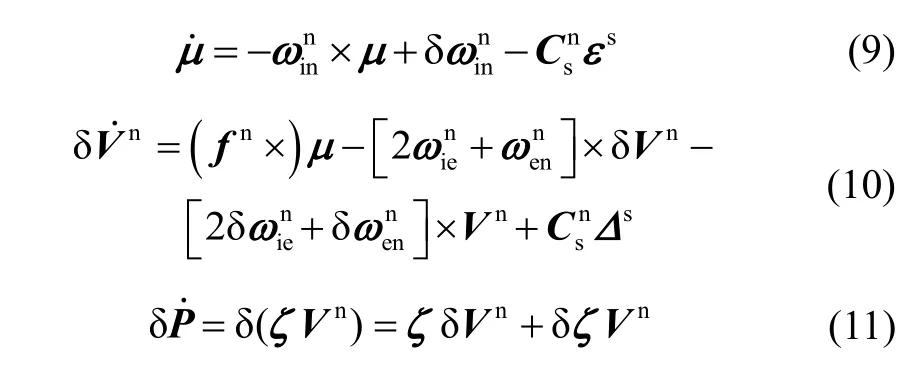
At the same time, the attitude error matrixФare as follows:

Due to the introduction of new errorthe error equation is changed, and the state equation of the system is also changed.
2 Kinematic constraint
When the vehicle is running on the ground under the ideal condition of no sideslip and jolt, the speed direction of the vehicle is mainly along the front of the vehicle body,and the speeds of the vehicle in both lateral and vertical directions are usually zero. That is
The velocity in b-framebVcan be obtained by the velocityin n-frame, attitude matrix matrixand attitude That is

The actual situation is slightly different. When the vehicle is making a turn, there may be sideslip, vehicle vibration and so on, which will cause the speeds on thexaxis and thezaxis of the vehicle to be not as zero as the ideal condition. Fig.2 is the actual speeds of an experiment in b-frame.
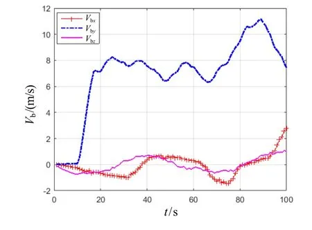
Fig.2 Actual speed values in b-frame
It can be seen that the speed cannot be simply regarded as zero or white noise. Through the analysis of speeds,the velocity model is established as random walk noise.Since the Kalman filter needs to satisfy the condition that the system noise and the measurement noise are the Gauss white noise, the measurement equation of the system needs to be processed by whitening colored noise so that the Kalman filter can be carried out.
3 Mathematical model of vehicle positioning
3.1 Establishment of state equation
On the one hand, the change of the speed and position in the height channel is not obvious and has little effect on the system, so the related components of this channel can be neglected; on the other hand, this system has the angular position errorThe state variable of the new method of RMINS is as follows:

In (14),Xis a 13-dimensional error state matrix,are position errors;are velocity errors;are attitude errors;is the angle measurement error of photoelectric encoder;are gyroscope’s drifts;are accelerometer’s biases.
The state equation of the system is as follows:
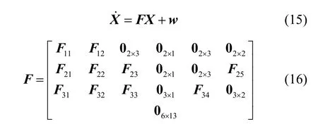
In (15)-(16),wis the process noise, assumed to be uncorrelated and zero-mean white noise;is a zero matrix;
3.2 Establishment of measurement equation
The measurement equation is established by using the kinematic constraint characteristic. It can be obtained from
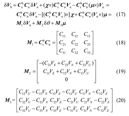
In (17)-(20),is the velocity error matrix in b-frame;is the value ofin thei-throw andj-th column.
It can be obtained from [10] and (13) that

can be regarded as one-order Markov process matrix, andξis the zero mean white noise matrix;~N(0,0.28) and
By ignoring the height channel, it can be obtained from (13) and (17)-(21) that

The measurement equation is as follows:

In (23),the measurement matrixis as follows:
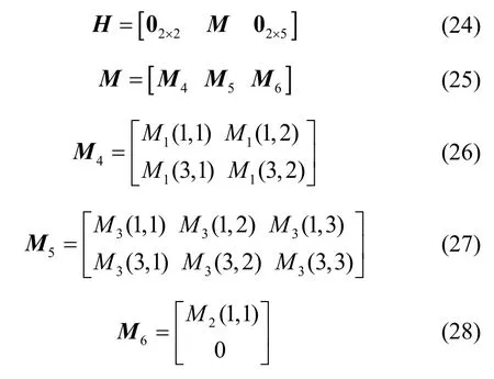
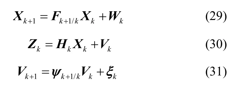
The discretization expressions of the equation (15),(23) and (21) are as follows:
4 Robust adaptive Kalman filter
The equation (23) does not satisfy the Kalman filter condition, so it is necessary to whiten the colored noise.At the same time, this system has the unmodeled error,the system measurement information is abnormal, and a priori information is limited for the above positioning method which may cause the system to diverge when the Kalman filter is carried out. Therefore, it is necessary to suppress the error in order to improve the positioning accuracy. The robust adaptive Kalman filter can restrain the dynamic model error and the measurement anomaly simultaneously.
4.1 Whitening of colored noise
In (29)-(31),are all uncorrelated and zero-mean white noise[14], and their variances areandrespectively.Supposing that

Therefore, the measurement equation can be written as

In (35),is the zero-mean white noise and its variance is

After the equation transformation, (33) and (35)satisfy the condition of Kalman filter.
4.2 Robust factor model
The determination of robust factor is based on the principle of equivalent weight, the robust factor is constructed by weight function, and the weight of observed value is reduced to reduce the share of abnormal observation in parameter estimation. In order to overcome the deficiency of discriminant condition of prior value and make full use of the current observation information, the discriminant condition based on Huber weight function is improved:
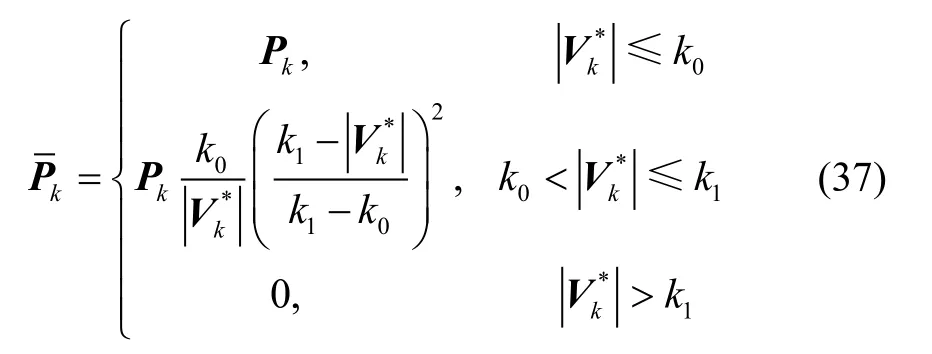
In (37),is the robust equivalent weight matrix of the observed value
When the number of the observed quantities is less than that of state parameters and the observed quantities may be abnormal, the improved calculation ofis as follows:

In (39),is the i component of the predicted residualis the sum of the diagonal matrix of the covariance matrixand

In (40),is the state prediction covariance matrix.
4.3 Adaptive factor model
Since the number of the selected observed quantities is less than that of state parameters, the adaptive factor is constructed here based on the predicted residual
As shown in (38), if the measurement value is reliable,reflects the reliability ofis the state information of system model, andreflects the error of system model. Using the predictive residualas the variable, the discriminant statistic of the state model error is constructed as follows:

According to the equation (41), the adaptive factor based on the three segment function model is further constructed as follows[13]:
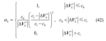
In (42),
It can be obtained from (41) and (42) thatwill decrease whenwill decrease to zero when
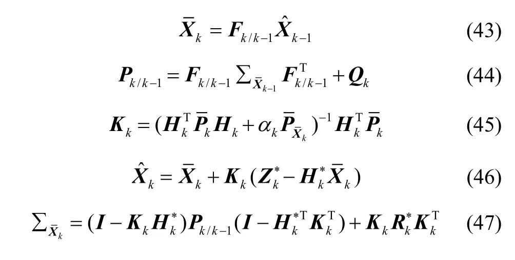
After completing the construction of the above robust factor and adaptive factor, the robust adaptive Kalman filter can be carried out on the basis of the knownand covariance matrixAt time k,andcan be obtained, and then the state estimation value of time k can be obtained by the following recursive equation:
5 Experimental results
As shown in Fig.3, the dynamic vehicle experiment was carried out in the area of East Gate of Northwestern Polytechnical University, and the route is repeated for the purpose of comparison. Fig.4 is the comparison of positioning error before and after rotation modulation.
It can be obtained from Fig.3 and Fig.4 that, after the introduction of rotation modulation, the positioning precision of the MEMS-RMINS is increased signifycantly for 100 s navigation time; the maximum position error of the East and North is reduced to 20.6 m and 38.6 m from 106.2 m and 273.6 m respectively. At the same time,it can also be seen that, because of the low accuracy of the selected MEMS-IMU devices, it can only work for 100 s under the requirement of a certain precision without other auxiliary information.
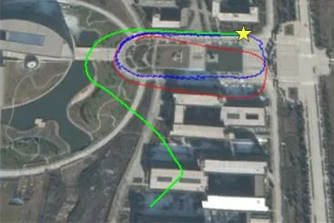
Fig.3 Comparison of different systems
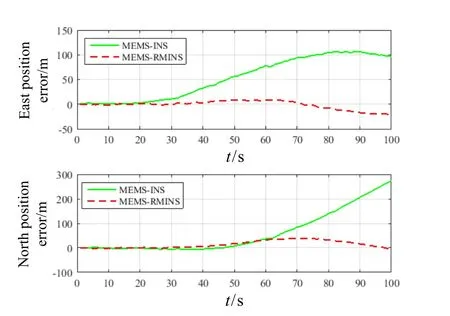
Fig.4 Comparison on position errors
Because of the existence of error sources, the positioning accuracy of MEMS-RMINS is still a large number, and the positioning error will be further increased with time. Therefore, other information needs to be introduced to suppress the growth of MEMS-RMINS’s error. In this work, the kinematic constraint and robust adaptive Kalman filter are introduced to improve the positioning accuracy.
The experimental results of those three schemes which include the MEMS-RMINS, the RMINS/KC+KF,and the RMINS/KC+RAKF are shown in Fig.5-Fig.7 for 150 s navigation time. In Fig.5 and Fig.6, the positions of the East and the North are all relative to the starting point.In Fig.7, the position error of the East and the North is all relative to the GPS outputs. It can be seen from these figures that, as time goes on, the error of MEMS-RMINS will continuously diverge, and the error can be effectively suppressed after the introduction of KC and KF or RAKF.
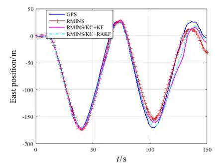
Fig.5 Comparison on east positions of different schemes
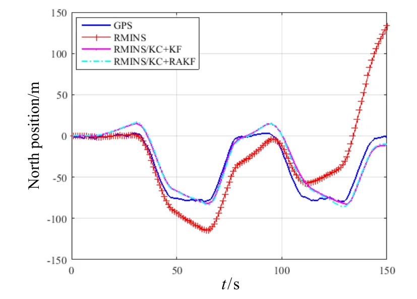
Fig.6 Comparison on north positions of different schemes
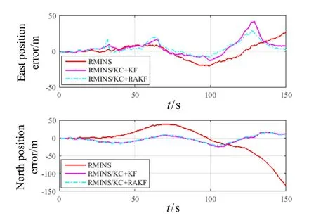
Fig.7 Comparison on position errors of different schemes
Based on the position of the GPS outputs, the maximum errors of the East and the North and the standard deviation are compared in different schemes, and the comparison results are shown in Tab.2. In order to better make comparison, the results of RMINS/GPS integrated navigation are also listed.
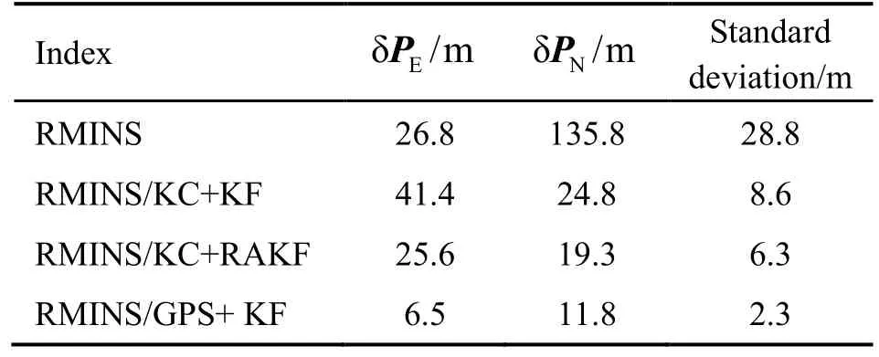
Tab.2 Comparison of experimental results
As can be seen from Tab.2 that, after the introduction of the KC and KF, the maximum error is reduced, in which the maximum position error of the North is reduced from 135.8 m to 24.5 m and the standard deviation is nearly 30% of the MEMS-RMINS’s, showing that the error is suppressed effectively. However, due to the influence of model errors and observation anomaly, the maximum value of the east position error increases, and the standard deviation is relatively large. Therefore, this work uses the RAKF to further improve positioning accuracy.
After the introduction of the RAKF, the maximum errors of the East and North are reduced, and the standard deviation of the RAKF is further reduced which is 73.3% of the KF’s. On the one hand, after introducing the kinematic constraint and using RAKF, the working time of the system is decreased to the 150 s from the original 100 s, and the positioning accuracy is improved;On the other hand, compared with KF, the maximum error or the mean square error is reduced by introducing the RAKF which changes the filter gain matrix and the mean square error matrix of the system by dynamically adjusting the robust factor and the adaptive factor. The experimental results show that RAKF has better robustness and adaptability.
6 Conclusions
It can be seen that the new method of vehicle positioning is feasible and can achieve very good positioning accuracy. It can work longer and has a higher accuracy.At the same time, it can draw the following conclusions:
1) In this work, a complete vehicle positioning method is presented, including MEMS-RMINS based on rotation modulation technology and the KC. This method uses MEMS-RMINS, the KC, and RAKF to achieve the real-time and high-precision positioning, and the standard deviation of this method reach meter’s level.
2) The velocity calculation results of b-frame show that the lateral and vertical velocities cannot be simply considered as white noise. The Kalman filter condition can be satisfied by establishing a more appropriate model and processing the state equation and measurement equation properly. The experimental results prove the correctness of the proposed method.
3) The experimental results show the correctness of the theoretical analysis and the feasibility of the practical application. With the advantages of the high positioning accuracy, good reliability and stable accuracy, this method has high application value.
It can see that the positioning error is still large.Therefore, in the following research, the positioning accuracy of the vehicle positioning method can be further improved by improving the filter method or using other auxiliary technologies.
[1] Groves P D. Principles of GNSS, inertial, and multisensor integrated navigation systems[M]. 2nd edition. London:Artech House, 2013.
[2] Liu F, Wang W, Wang L, et al. Error analyses and calibration methods with accelerometers for optical angle encoders in rotational inertial navigation systems[J]. Applied Optics, 2013, 52(32): 7724-7731.
[3] 孙尧, 王庭军, 高延滨, 等. 旋转式捷联惯导系统解算结构[J]. 中国惯性技术学报, 2013, 21(1): 10-15.
Sun Y, Wang T J, Gao Y B, et al. Computation structure of rotating strapdown INS[J]. Journal of Chinese Inertial Technology, 2013, 21(1): 10-15.
[4] Jia Y, Li S L, Qin Y Y, et al. Error analysis and compensation of MEMS rotation modulation inertial navigation system[J]. IEEE Sensors Journal, 2018, 16(24): 2023-2030.
[5] Jia Y, Li S L, Xu Y F. Analysis and compensation of rotating shaft fluctuation on rotation inertial navigation system[C]//IEEE Chinese Guidance, Navigation and Control Conference (IEEE CGNCC2016). 2016: 609-613.
[6] Collin J. MEMS IMU carouseling for ground vehicles[J].IEEE Transactions on Vehicular Technology, 2015, 64(6):2242-2251.
[7] Wang X Y, Wang W, Wang L. Rotation modulation for strap-down inertial navigation system based on MEMS sensors[J]. Journal of Northeastern University, 2014, 35(4):494-498.
[8] Sun W, Wang D X, Xu L W. MEMS-based rotary strapdown inertial navigation system[J]. Measurement, 2013,46(8): 2585-2596.
[9] Du S, Sun W, Gao Y. MEMS IMU error mitigation using rotation modulation technique[J]. Sensors, 2016, 16(12):494-498.
[10] Du S, Sun W, Gao Y. Integration of GNSS and MEMS-based rotary ins for bridging GNSS outages[C]// China Satellite Navigation Conference (CSNC) 2015 Proceedings: Volume III. Lecture Notes in Electrical Engineering,vol. 342. Springer, Berlin, Heidelberg, 2015.
[11] Won D, Ahn J, Sung S, et al. Performance improvement of inertial navigation system by using magnetometer with vehicle dynamic constraints[J]. Journal of Sensors, 2015,vol.2015: (1-11).
[12] Yan W L, Bastos L, Xu T H, et al. Image-aided platform orientation determination with a GNSS/low-cost IMU system using robust adaptive Kalman filter[J]. GPS Solutions,2018, 22(1): 1-12.
[13] Zhang Q J, Zhao L D, Zhao L, et al. An improved robust adaptive Kalman filter for GNSS precise point positioning[J]. IEEE Sensors Journal, 2018: 99(1-9).
[14] Qin Y Y, Zhang H Y, Wang S H, et al. Kalman Filter and integrated navigation principle[M]. Xi’an, China:Northwestern Polytechnic University Press, 2012.

