Doping effects on the electro-degradation of phenol on doped titanium suboxide anodes☆
Xuan Yang ,Jiuji Guo ,Zhaowu Zhu ,Hui Zhang ,*,Tao Qi,*
1 Institute of Process Engineering,Chinese Academy of Sciences,Beijing 100190,China
2 University of Chinese Academy of Sciences,Beijing 100049,China
1.Introduction
With the development of chemical industry,large amounts of various organic compounds are discharged into the environment.Phenol was usually found in polluted steams and groundwater.As a toxic organic compound,phenol can damage fish even in a concentration level of 2 mg·L-1[1].Phenol has been listed on the top among the pollutants which required treatment by the United States Environmental Protection Agency[2,3].Therefore,it was commonly used as the typical pollutant for the investigation of wastewater treatments[4].
To remove phenolic pollutants from waste water,a large number of methods have been developed,including adsorption,oxidization and biodegradation[4].Electrochemical oxidization approach has attracted much attention due to its easy management and less secondary pollution[5–7].Boron-doped diamond(BDD)electrodes[8,9]and Ir/Ru modi fied dimensionally stabilized anodes(DSAs)[1,10]have been reported to be effective for some organic compound degradation.However,the high price of diamond film and Ir/Ru materials limited their applications.
The titanium suboxide(TinO2n-13<n<10)have perfect electrical conductivity and chemical resistance.Ti4O7has attracted much interest since the 1990s as the major compound in electrochemical electrodes to well deal with polluted water and to use as the bipolar electrodes due to the best conductivity[11,12].However,it is difficult to prepare pure Ti4O7by reducing TiO2because of the very narrow Gibbs energy gap from Ti3O5to Ti4O7,and then to Ti5O9[13].Recently,bene fiting from a novel co-deposited route,tons of pure Ti4O7powders(phase purity>99%)can be produced in our cooperation plants.It provided the possibility to compare the efficiency of phenol degradation on the pure Ti4O7anode and the traditional mixed TinO2n-1anodes.In addition,doped titanium suboxide electrode was rarely investigated although doping is the most popular strategy to modify semi-conductive materials.
The doping reagentof Gallium and Yttrium has been reported to enhance the conductivity and photodegradation activity of TiO2material due to the reduced energy gap[14,15].Inspired by these works,the doping effects to titanium suboxide were investigated in this article.The differences were carefully studied for the electro-degradation of phenol in Na2SO4solutions on the anodes of pure Ti4O7,the mixedcrystal Ti4O7and Ti5O9(labeled as Ti4O7–Ti5O9),the Y-doped Ti4O7,and the Ga-doped Ti4O7.Chemical oxygen demand(COD)was measured to evaluate the electro-oxidation capability.The apparentkinetics and cumulative current efficiency(CE)were calculated based on the COD.The intermediates in the experiments were identified by HPLC to reveal the degradation route.The results implied that the phenol was oxidized to oxalate molecules via different routes on different doped anode surfaces,and finally oxidized thoroughly to CO2and H2O.The mechanisms were proposed at the end.
2.Experimental
2.1.Materials
Pure Ti4O7powder and the Ti4O7–Ti5O9mixed-crystal powder were obtained from the Shandong League Chemical Group Co.,Ltd.(China).The powder sizes were+180 mesh(<80 μm).The doping reagents(Y2O3and Ga2O3)were of analysis grade purchased from Sinopharm Chemical Reagent Beijing Co.,Ltd.Polyimide power was purchased from Hangzhou Sumengte Company.
Authentic substances were purchased from Sinopharm Chemical ReagentBeijing Co.Ltd.,including pyrocatechol,hydroquinone,benquinone oxalate,formic acid,maleic acid and α-ketoglutaric acid.
2.2.Preparation and characterization
0.5 g doping reagent was mixed with 100 g Ti4O7powder.Then the mixtures,the pure Ti4O7powder,and the Ti4O7–Ti5O9powder were mixed with 10 wt%of polyimide powder,respectively.Each mixture was compressed at 200 MPa in a 7.5 cm×12.6 cm mold and then was heated at 170°C for an hour.After cooling down,the plates were taken out from the mold and were calcined under Ar flow in 1273 K.The finalplates played as the anodes in degradation,which were labeled as Y-doped Ti4O7,Ga-doped Ti4O7,Ti4O7and Ti4O7–Ti5O9,respectively.
The X-ray diffractions(XRD)were performed on an Empyrean X-ray diffractometer with monochromatic CuKa radiation(λ=1.5418 nm).The step-scan covered the angular range from 5°to 90°at a scan rate of 1.5(°)·min-1using silicon as internal standard.The XRD peaks were re fined by using the Highscore plus software and fitted by the Rietveld function to estimate the phase purities.The morphologies were observed by using the SEMmode on a MineralLiberation Analyzer(FEI MLA 250).The EDX was performed on the same.
2.3.Electrochemical degradation
The electro-degradation of phenol was performed in a 500 ml glass beaker with magnetic stirring.The initial solution consisted of 0.1 mol·L-1Na2SO4and 1.04 mmol·L-1phenol.A titanium plate and the titanium suboxide anode were immersed into the solution with a 4 cm gap.
Chemical oxygen demand(COD)was determined by the fast digestion spectrophotometric method[16].The current efficiency(CE)for COD decline was calculated using the following equation:

The concentration of phenol and possible intermediates was measured by HPLC with an ACQUITY UPLC BEH C18 column and MS/UV–vis detectors.Pure methanol was used to clean the column.The species of intermediates were identified by HPLC-MS with pure water as the mobile phase.A UV–vis detector was utilized to determinate the retention time and concentrations.In the later case,90 ml methanol and 10 ml of 1 mmol·L-1H3PO4aqueous solution were mixed to be the mobile phase.
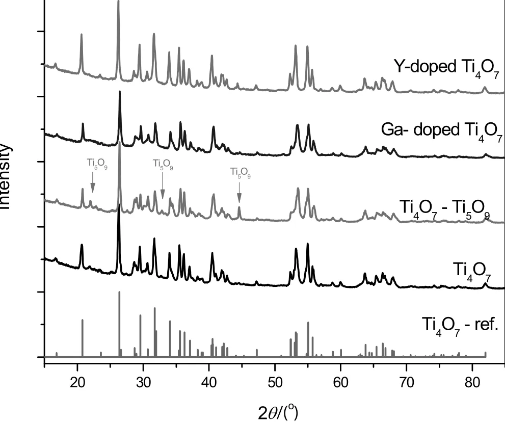
Fig.1.XRD patterns of the four anodes.
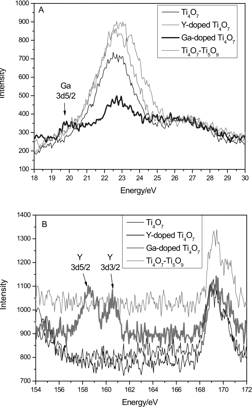
Fig.2.The identified peaks of Ga(A)and Y(B)in the XPS spectra of the anodes.
3.Results and Discussion
3.1.Characterization of titanium suboxide anodes
The phases of samples were identified by XRD,as shown in Fig.1.The Ti4O7sample exhibited the typical peaks of Ti4O7(purity≥98%)while the Ti4O7–Ti5O9sample was estimated to be of 56.3%Ti4O7and 43.7%Ti5O9by using XRD quantitatively re fined method.For the two doped samples,only the simple peaks of Ti4O7were found.The characteristic peaks of Ga2O3and Y2O3did not appear in the XRD patterns,implying the doping elements had been highly dispersed without any separated aggregation phase.However,the doping elements gave their identified peaks in the XPS spectra(Fig.2).The identified peak of Ga5d5/2 was found only in the sample of Ga-doped sample,as well as the peaks of Y3d5/2 and Y3d3/2 were found only in the sample of Y-doped sample,as Fig.2 shows.
The SEM images(Fig.3)reveal that the surface of all anodes was similarly coarse and porous.Since the polyimide particles in the precursor had been burned out,some residual pores were expected.The coarse and porous surface would be in favor of electrochemical reactions.The cauli flower-like aggregates were constructed by spherical primary titanium suboxide particles.The aggregates and the pores were of micrometer scale.
3.2.Chemical oxygen demand(COD)and current efficiency
The electro-oxidation was performed under a certain constant voltage for 5 h.Fig.4 shows the current and COD on the Y-doped anodes during the phenol electro-degradation.It was observed the higher voltage resulted in the higher current.Furthermore,the current quickly decreased in the first half hours and then smoothly decreased.At the same time,the COD decreased with the increasing time.The average currents,COD removal ratios,and the surface current ef ficiencies were calculated on the four different anodes under different voltages.The results were demonstrated in Fig.5.It is obvious the highest COD removal was assigned to the Y-doped anode,and 3.5 V was the optimal efficient voltage to remove COD for any anode.The exact data were listed in Table 1.
From Table 1,the Ga-doped anode showed the minimum COD removal ratio under each given voltage,and the Y-doped sample showed the optimum COD removal ratio(72%at 3.5 V).The results implied the doping reagent could greatly affect the electro-degradation activity.For each test anode,the highest COD removal ratio was always observed at 3.5 V while the average current was around 2.5 mA·cm-2(see Table 1).Similar phenomenon was reported by Geng[17]that the highest COD removal ratio(95.3%in 3 h)on a Ti4O7nanotube anode was observed at the current density of 2.5 mA·cm-2(voltage around 2.5 V).Either higher or lower current density resulted in lower removal ratio because a relatively larger percentage of energy was consumed by the oxidation of water companying with oxygen gas releasing[17].It is implied that the diffusion of phenol may play an important role in the rate-limiting steps.A suf ficiently high voltage would result in the much restrictive transport limitation of organic species,as the relevant article revealed[18].During our experiments,it was observed that bubbles appeared on the surface of anode when the voltage was higher than 4.0 V.The bubbles covered on the anode surface would also suppress the electrochemical degradation[19].Considering the conclusions,the following experiments were carried on under the constant voltage of 3.5 V.
3.3.Kinetics analysis of phenol degradation
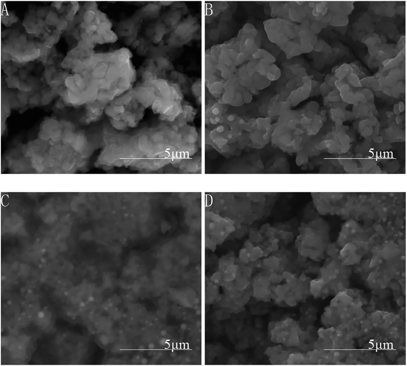
Fig.3.SEM images of the anodes:(A)pure Ti4O7,(B)Ti4O7–Ti5O9,(C)Ga-doped Ti4O7,(D)Y-doped Ti4O7.
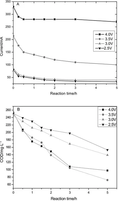
Fig.4.The current(A)and COD curves(B)during the electro-degradation on the Y-doped anode.
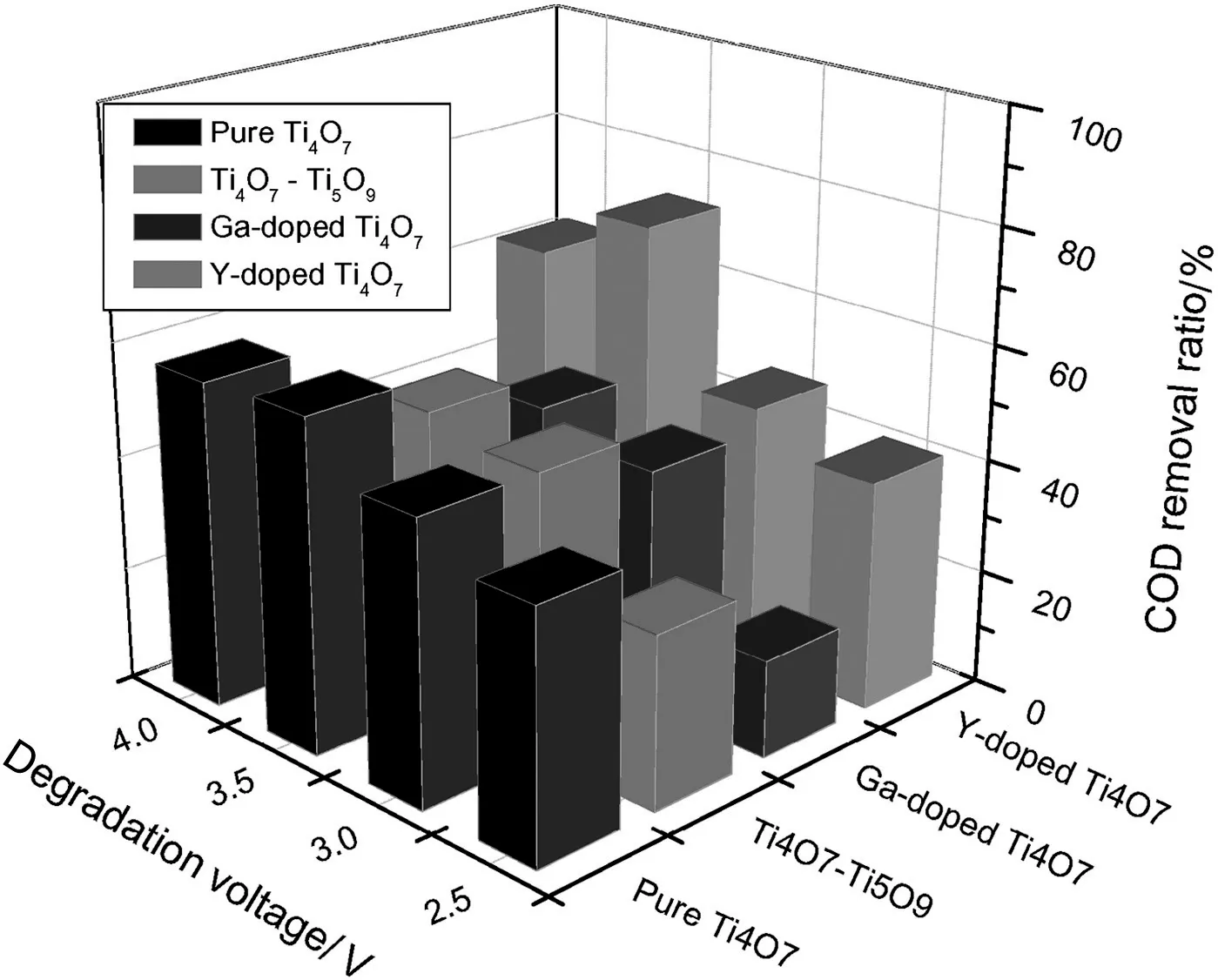
Fig.5.The COD removal ratios in 5 h under different voltages on the four anodes.
The concentrations of phenol were measured by HPLC during the degradation in 9.5 h.The curves are showed in Fig.6.At the end of the experiment,the concentration of phenol was 0.326 mmol·L-1for the pure Ti4O7anode and 0.351 mmol·L-1for the Ga-doped Ti4O7anode,respectively.However,for the Y-doped Ti4O7anode,the concentration of phenol just dropped from 1.04 to 0.425 mmol·L-1.The comparison indicated the Y-doped Ti4O7anode was relatively not good to destroy phenol.
It is strange that the Y-doped anode had the highest COD removal,as shown in Table 1.The tension probably attributes to the fact that the chemical oxygen demand(COD)is related to the total oxidable substances in solutions,including various intermediate compounds,but not only phenol.Thus,the highest COD removal ratio and the highestconcentration of residualphenolmightimply the leastintermediates accumulated during the electro-degradation on the Y-doped Ti4O7anode.The assumption was supported by the following HPLC analysis.
The kinetics analysis indicated that the phenol electro-degradation was a first-order reaction.Fig.6(A)demonstrates the concentrations of phenol during the degradation.The concentration and the time in a first-order reaction follow the equation:d C/d t=-kC,which also equals to the equation ln(C0/C)=kt.It means there was a linear relationship between the ln(C0/C)and the time,and the slope is the apparent rate constant(k)[20].As Fig.6B and Table 2 display,the correlation coefficients are very close to 1.0,suggesting that the first order model agreed well with the reaction of phenol degradation.The degradation rate constants were listed in Table 2.
3.4.Intermediates and degradation mechanism
The electro-degradation mechanism of phenol was investigated by many researchers[2,12,21].Usually,hydroquinone and/or benzoquinone were the first-step intermediates in the degradation progress,and then broke to open-ring carboxylic acids.The carboxylic acids were further degraded to oxalate and/or formic acid.Finally,organic pieces are thoroughly mineralized to CO2and H2O.
In this article,the intermediates during the electro-degradation of phenol were identified by HPLC–MS,as Table 3 shows.The intermediates included a series of aliphatic dicarboxylic acid and unsaturated dicarboxylic acid.According to the list,pure reagents of the key intermediates were quantitatively injected to calibrate the individual peaks in HPLC–UV chromatograms.
From the HPLC chromatograms(Fig.7),typical intermediates were found during the electro-degradation on the pure Ti4O7anode,including benzoquinone and hydroquinone(carbon-six,C6),oxalate and maleic acid(C2+C4),formic acid and α-ketoglutaric acid(C1+C5)[1,5,10,22,23].The isomers of benzoquinone and hydroquinone were the first order intermediates during the electro-oxidation of phenol[5,22,23].It is believed that phenol firstly reacted with various radicals,especially with OH radical,resulting in a series of phenoxy radical reactions and then transformed to benzoquinone[1,11,12].As the key intermediate,benzoquinone reacted prior with free radicals to transform to carboxylic acids but was not oxidized by electrode.However,during the experiments of the Y-doped anode,the peak of benzoquinone and hydroquinone did not appear in the HPLC chromatograms,implying these intermediates might be not necessary for degradation.
The concentrations of the intermediates were integrated from the HPLC chromatograms of the solution samples.Fig.8 displays the concentration curves of the intermediates during the electro-degradation on the pure Ti4O7anode.All concentrations increased at the early stage and then decreased due to the balance between generations and destructions.As the apex concentration of α-ketoglutaric acid(C5)was much higher(15 t)than that of maleic acid(C4),the main routes were suggested to be the reaction C6→C5+C1.Subsequently,C5 and C4 were decomposed to oxalate.At final,oxalate and formic acid were thoroughly oxidized to CO2and H2O.
The concentrations of intermediates on the Ga-doped Ti4O7anode were measured and are shown in Fig.9.Benzoquinone and hydroquinone(C6),maleic acid and oxalate(C4+C2)were found.Formic acid(C1)and α-ketoglutaric acid(C5)were not found,implying thereaction of C6→C5+C1 was probably not executed.The first-step degradation route was only C6→C4+C2.The apex concentration of benzoquinone was much higher(3–5 t)than that on the pure Ti4O7anode.The apex concentration of oxalate reached to 1.41 mmol·L-1at the eighth hour, five times higher than thaton the pure Ti4O7anode and three times higher than that on the Y-doped anode.

Table 1 The average currents and COD removal ratios in the electro-degradations(5 h)
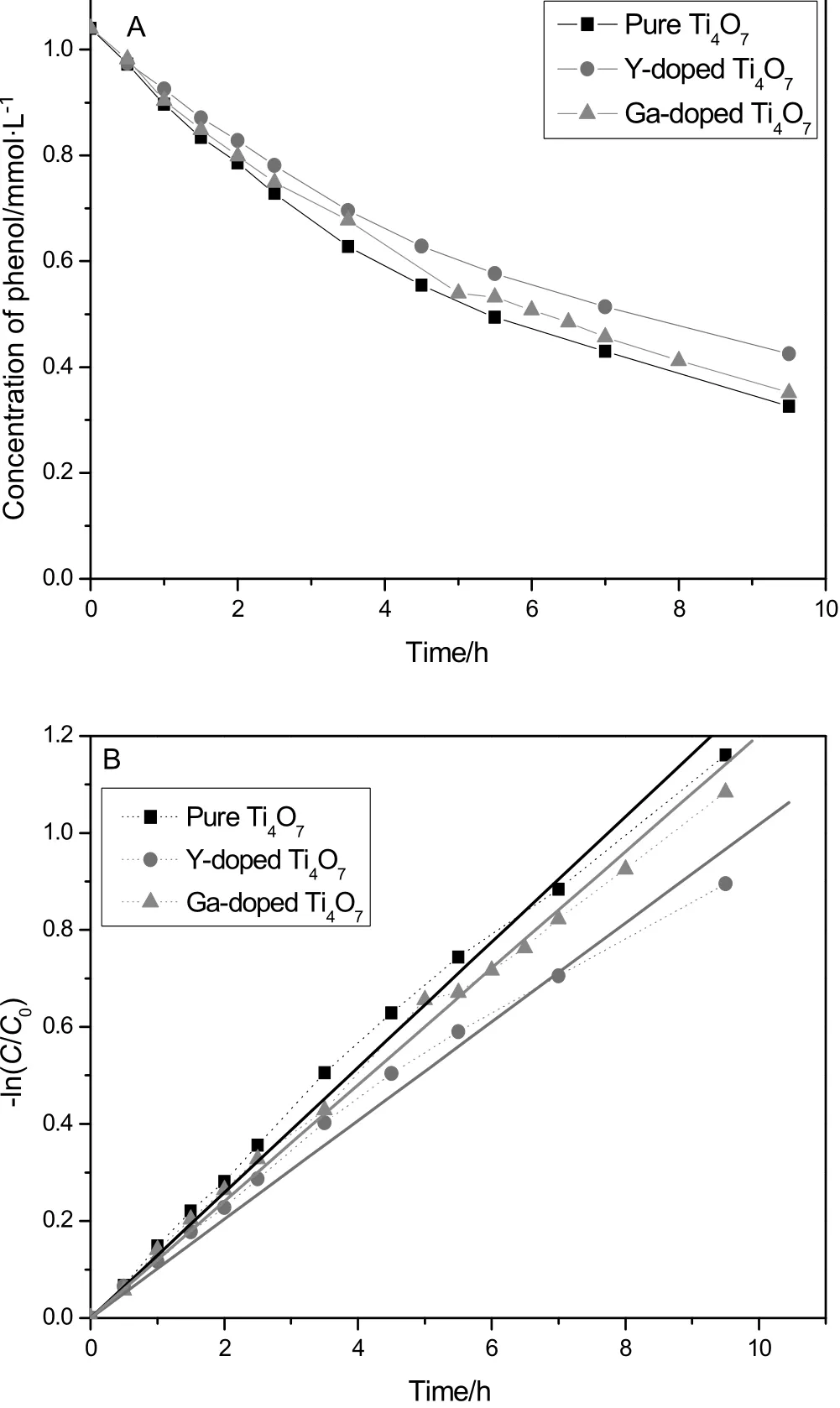
Fig.6.The concentration curves of phenol(A)and the kinetics plot(B)on the different anodes.

Table 2 Kinetics data of the phenol degradation on the different anodes

Table 3 MS peaks and retention time of the possible intermediates
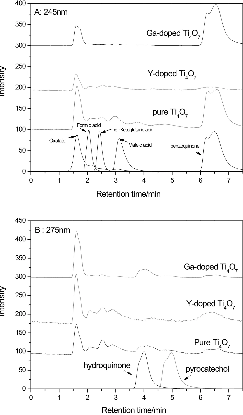
Fig.7.HPLC chromatograms of the solution after a one hour degradation on the pure Ti4O7 anode and the peaks of the pure intermediates at different UV wavelengths(245 nm and 275 nm).

Fig.8.The concentrations of intermediates during the degradation on the pure Ti4O7 anode.
It is known that the concentration of residual phenol was 0.41 mmol·L-1at the eighth hour during the electro-degradation(Fig.6).As the original concentration was 1.04 mmol·L-1,0.63 mmol·L-1phenolhad been decomposed.Considering the reaction from phenol(C6)to H2C2O4(C2)could ideally give three times of oxalate,0.63 mmol·L-1phenol equals to 1.89 mmol·L-1oxalate.Thus,the concentration of the accumulated oxalate(1.41 mmol·L-1)means that the surface yield of oxalate was as high as 74.6%.Due to the minimum COD removal ratio on the Ga-doped anode,as Table 1 demonstrates,it was reasonably speculated that the anode was too weak to oxidize organic compounds,especially oxalate.As the result,oxalate could be accumulated.
For the Y-doped Ti4O7anode,the curves of concentration are shown in Fig.10.It was checked again that the typical aromatic intermediates of benzoquinone,hydroquinone and pyrocatechol were surely not detected.Only three intermediates were found during the degradation progress of phenol,including maleic acid(C4),oxalate(C2)and α-ketoglutaric acid(C5).The concentration of α-ketoglutaric acid(C5)was transient and several ten times lower than that on the pure Ti4O7anode.Furthermore,the concentration of maleic acid(C4)was much higher than that of α-ketoglutaric acid(C5).All the proofs implied that the major degradation route was of phenol→C4+C2 for the Y-doped anode.

Fig.9.The concentrations of intermediates during the degradation on the Ga-doped Ti4O7 anode.
Since the concentration of oxalate on the Y-doped Ti4O7was much lower than that on the Ga-doped Ti4O7,as the different factor,the different doping elements must play very important roles in the degradation progress of oxalate.The handbooks[24,25]reveal that the first stability constants(lg K1)of Y(C2O4)33-,TiO(C2O4)22-,and Ga(C2O4)33-are 6.52,2.67,and1.48,respectively.The much higher stability constant indicated that the coordinate–covalent bond between oxalate and Y is much stronger than that between oxalate and Ga.In the similar electrolyte environment,it means that there were more oxalate molecules which coordinate/bound with the external Y atoms on the anode surface.Reasonably,the anode could take electrons away from the bounded oxalate molecules more easily than from those molecules dispersed in the solution,resulting in an anodic oxidization.The weaker coordinate–covalent bond between oxalate and Ga means more oxalate could be survived and accumulated.As for the pure Ti4O7,lots of phenol molecules were transformed to formic acid(C1)and α-ketoglutaric acid(C5)in the degradation progress.It is obviously that C1 could not be transformed to C2(oxalate)in the degradation and the transformation from C5 to C2 has to waste one carbon at least.Since these bypass reactions have very low efficiency in producing oxalate,the surface yield of oxalate on pure Ti4O7was the lowest(20%).

Fig.10.The concentrations of intermediates during the degradation on the Y-doped Ti4O7 anode.
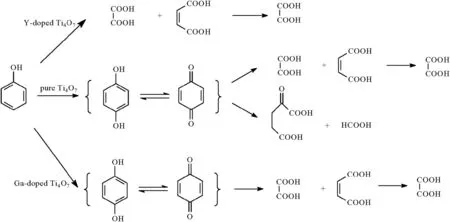
According to the above discussion,the proposed degradation routes are shown in Scheme 1.Oxalate and occasionally formic acid were the ending organic spices,and finally were oxidized to CO2and H2O.By doping Ga or Y in Ti4O7anodes,the oxidization ability and degradation routes were greatly changed.The experiment of Y-doped Ti4O7anode proved that the carbon-six intermediates were not necessary for the degradation of phenol.And a potential electrocatalyst of Ga-doped Ti4O7anode was found to efficiently produce oxalate from phenol.
4.Conclusions
In the article,the electro-degradations of phenol were performed on different Ti4O7-based anodes to study the doping effects.The optimal efficientvoltage was found to be 3.5 Vto remove CODfor alltestanodes.
As the control sample,pure Ti4O7anode was the best one to decompose phenol to various intermediates.The kinetics constant was 0.129 h-1forthe phenoldegradation.The degradation route wasclassic with the intermediates of benzoquinone and hydroquinone(C6),α-ketoglutaric acid(C5)and formic acid(C1),maleic acid(C4)and oxalate(C2).
As the best achievement in COD removal,the Y-doped Ti4O7anode displayed its strong oxidization ability.72%of COD was removed in 5 h.The mechanism investigation demonstrates phenol was directly decomposed to open-ring molecules.The result also proved that the carbon-six intermediates might not be necessary for the degradation of phenol.
For the anode of Ga-doped anode,in contrast to the Y-doped anode,the minimum COD removal ratio implied weak oxidization ability.As the result,high concentration of oxalate(1.41 mmol·L-1)was accumulated.The surface yield of oxalate was as high as 74.6%,suggesting a promising electro-catalyst to efficiently produce oxalate from phenol.
In summary,by using different doping reagents,the remarkable in fluences were observed and compared in the electro-degradation experiments.The doped titanium suboxide anodes exhibited multiple potentialities in wastewater treatments and electrochemical organic syntheses.
Scheme 1.Three proposed degradation routes for the electro-degradation of phenol.
References
[1]M.Li,C.Feng,W.Hu,Z.Zhang,N.Sugiura,Electrochemical degradation of phenol using electrodes of Ti/RuO2–Pt and Ti/IrO2–Pt,J.Hazard.Mater.162(1)(2009)455–462.
[2]P.Jin,R.Chang,D.Liu,K.Zhao,L.Zhang,Y.Ouyang,Phenol degradation in an electrochemical system with TiO2/activated carbon fiber as electrode,J.Environ.Chem.Eng.2(2)(2014)1040–1047.
[3]F.Zhang,M.Li,W.Li,C.Feng,Y.Jin,X.Guo,J.Cui,Degradation of phenol by a combined independent photocatalytic and electrochemical process,Chem.Eng.J.175(2011)349–355.
[4]Y.T.Lin,C.Liang,J.H.Chen,Feasibility study of ultraviolet activated persulfate oxidation of phenol,Chemosphere 82(8)(2011)1168–1172.
[5]Y.M.Awad,N.S.A.,Electrochemical treatment of phenolic wastewater:efficiency,design considerations and economic evaluation,J.Environ.Sci.Health A 30(1997)2185–2203.
[6]N.V.R.Kannan,L.J.Berchmans,S.N.Sivadurai,Removal of phenolic compounds by electrooxidation method,J.Environ.Sci.Health A Environ.Sci.Eng.Toxic Hazard.Subst.Control A30(1995)2185–2203.
[7]R.Kötz,S.S.,B.Carcer,Electrochemicalwaste watertreatmentusing high overvoltage anodes.Part I:physical and electrochemical properties of SnO2anode,J.Appl.Electrochem.21(1)(1991)14–20.
[8]C.R.Costa,F.Montilla,E.Morallon,P.Olivi,Electrochemical oxidation of synthetic tannery wastewater in chloride-free aqueous media,J.Hazard.Mater.180(1–3)(2010)429–435.
[9]X.Zhu,J.Ni,J.Wei,P.Chen,Scale-up of B-doped diamond anode system for electrochemical oxidation of phenol simulated wastewater in batch mode,Electrochim.Acta 56(25)(2011)9439–9447.
[10]E.Chatzisymeon,S.Fierro,I.Karafyllis,D.Mantzavinos,N.Kalogerakis,A.Katsaounis,Anodic oxidation of phenol on Ti/IrO2electrode:Experimental studies,Catal.Today 151(1–2)(2010)185–189.
[11]P.C.S.Hay field,R.L.Clarke,in:J.D.Genders,N.L.Weinberg(Eds.),Electrochemistry for a Cleaner Environment,Electrosynthesis Co.Inc.,East Amherst,NY 1990,p.87.
[12]A.M.Zaky,B.P.Chaplin,Mechanism of p-substituted phenol oxidation at a Ti4O7reactive electrochemical membrane,Environ.Sci.Technol.48(10)(2014)5857–5867.
[13]L.Fan,L.Wenchao,Thermodynamics of Metallurgy and Materials,Metallurgical Industry Press,2012 435.
[14]J.W.Pan,C.Li,Y.F.Zhao,R.X.Liu,Y.Y.Gong,L.Y.Niu,X.J.Liu,B.Q.Chi,Electronic properties of TiO2doped with Sc,Y,La,Zr,Hf,V,Nb and Ta,Chem.Phys.Lett.628(2015)43–48.
[15]R.Wang,F.Wang,S.An,J.Song,Y.Zhang,Y/Eu co-doped TiO2:synthesis and photocatalytic activities under UV-light,J.Rare Earths 33(2)(2015)154–159.
[16]Water Quality—Determination of the Chemical Oxygen Demand—Fast Digestion-Spectrophotometric Method.Ministry of Environment Protecting Agency of the People's Republic of China,2007 427.
[17]P.Geng,J.Su,C.Miles,C.Comninellis,G.Chen,Highly-ordered Magnéli Ti4O7nanotube arrays as effective anodic material for electro-oxidation,Electrochim.Acta 153(2015)316–324.
[18]G.Chen,Electrolytic oxidation of trichloroethylene using a ceramic anode,J.Appl.Electrochem.29(1999)961–970.
[19]A.P.Watkinson,Anodic oxidation of phenol for waste water treatment,Can.J.Chem.Eng.58(6)(1980)52–59.
[20]Y.Liu,Aqueous p-chloronitrobenzene decomposition induced by contact glow discharge electrolysis,J.Hazard.Mater.166(2–3)(2009)1495–1499.
[21]D.Bejan,J.D.Malcolm,L.Morrison,N.J.Bunce,Mechanistic investigation of the conductive ceramic Ebonex®as an anode material,Electrochim.Acta 54(23)(2009)5548–5556.
[22]J.E.Graves,D.Pletcher,R.L.Clarke,F.C.Walsh,The electrochemistry of magneli phase titanium oxide ceramic electrodes 1.The deposition and propertise of metal coatings,J.Appl.Electrochem.21(1991)848–857.
[23]P.C.S.Hay field,Development of a New Material:Monolithic Ti4O7Ebonex Ceramic,Royal Society of Chemistry,2001 11.
[24]J.A.Dean,Lange's Handbook ofChemistry,13th ed.The Science Publishing Company,1991 5–87.
[25]Q.L.Zhang,Inorganic Chemistry Books,vol.2,The Science Publishing Company,1984,578.
 Chinese Journal of Chemical Engineering2018年4期
- Chinese Journal of Chemical Engineering的其它文章
- An innovative design of septic tank for wastewater treatment and its performance evaluation:An applicable model for developing countries
- CFD modeling of turbulent reacting flow in a semi-batch stirred-tank reactor☆
- Synergistic and interference effects in coaxial mixers:Numerical analysis of the power consumption☆
- Atomic layer deposition of Al2O3 on porous polypropylene hollow fibers for enhanced membrane performances☆
- Experimental investigation and cost assessment of the salt production by solar assisted evaporation of saturated brine☆
- Equilibrium of liquid-liquid extraction of 2-phenylbutyric acid enantiomers:Experiment and model☆
