Preparation of PVC/PVP composite polymer membranes via phase inversion process for water treatment purposes
Ahmed Bhran ,Abeer Shoaib *,Doaa Elsadeq Ayman El-gendi,Heba Abdallah
1 Chemical Engineering Department,College of Engineering,Al Imam Mohammad Ibn Saud Islamic University(IMSIU),Al Riyadh,Saudi Arabia
2 Department of Petroleum Re fining and Petrochemical Engineering,Faculty of Petroleum and Mining Engineering,Suez University,Suez,Egypt
3 Chemical Engineering and Pilot Plant Department,Engineering Research Division,National Research Centre,Dokki,Giza,Egypt
4 Chemical and Materials Engineering Department,King Abdulaziz University,Jedda,King of Saudi Arabia
1.Introduction
Recently,the need for fresh water for various applications is raising with the growth of the world population.It was noted that most of the world water resources are mainly saline water.Furthermore,the fresh water(~2.5%)is either stored underground or in the form of ice/snow covered mountainous areas.This scarcity of fresh water is driving the implementation of water/wastewater treatment and especially water desalination,which is investigation on an increasing large scale[1,2].Polymeric membranes have gained very important place in water treatment technology due to their excellent behavior.Membranes could have relatively high efficiency and save energy withoutany chemicals addition;this behavior enhances researchers to focus on membrane technology.This technology is environmentally benign and became the preferred technology over conventional separation processes like filtration,distillation and ion exchange,for producing high-quality products,and providing greater flexibility in the system design[3–5].
Many ways could be used to prepare porous polymeric films,such as stretching,sintering,phase separation processes and track etching.Controlled phase separation of polymer solutions is the most common technique through the above mentioned ways[6].Phase-inversion process consists of the induction of phase separation in a previously homogeneous polymer solution.This process could be carried out in wet or dry media.Wet media involves change in temperature via immersing the solution in a coagulation bath,while dry media involves the introduction ofthe polymeric filmto a nonsolventatmosphere[4,7].
The membrane works as a semi-permeable barrierwhich allows passing of single or more species or compounds of a gaseous and/or liquid mixture or solution under a certain driving force[8–10].This driving force could be a change in,concentration,pressureor voltage.Membrane processes could be classi fied as microfiltration(MF),ultra filtration(UF),nano filtration(NF),reverse osmosis(RO),dialysis(D),electro dialysis(ED),pervaporation(PV),membrane distillation(MD)or gas separation(GS).This classi fication depends mainly on the separated species particle size and the applied driving force[11–13].Compared with other membrane separation processes,using MD has many attractive features.These features include mild operating conditions,total rejection of salt could be achieved;intensive to feed concentration,as well as stable performance at high contaminant concentrations[2].Additionally,MD process experiences less fouling due to the relatively large pore size of the membrane required for it.Furthermore,MD is able to use alternative energy sources,such as solar energy[14].
Membrane distillation is a thermally and pressure driven process in which hot and cold water streams could be separated through a hydrophobic micro porous membrane.Liquid water is prevented from passaging through the membrane due to its hydrophobic nature;however,vapor is allowed to pass,and vapor pressure gradient is evolved due to the difference in temperature.This consequently leads to the passage of water vapor through the membrane and condensation of iton the coldersurface[15].Therefore,high permeability,high hydrophobicity and low thermal conductivity are important properties needed for the production of a good MD material.MD materials usually have pore size ranging from 100 nm to 1 μm.It is found that the best pore size range for various MD applications depends mainly on the type of impurity(solute)in the feed stream.However,the pore size value would be investigated in the range of 0.1 to 0.45 μm.Smaller pore sizes may reduce the distillate flux,while larger pore size may increase risk of pore wetting.The maximum recommended pore radius is found to be in the range of 0.5 to 0.6 μm[2,14,16].

Table 1 Different composite PVC membranes
Both polymeric and inorganic membranes of hydrophobic nature could be used for MD process.However,commercial microporous hydrophobic polymeric membranes made of polypropylene(PP),polyvinylidene fluoride(PVDF)and polytetra fluoroethylene(PTFE)have attracted much more attention as a result of low values of surface tension[17–20].The change in the cold side processing nature of the permeate could result in different MD system configurations.One of these configurations is Direct Contact Membrane Distillation(DCMD),where the membrane is in direct contact with liquid phases.Air Gap Membrane Distillation(AGMD)is another configuration,where an air gap is interrupted between the membrane and a condensation surface.In Vacuum Membrane Distillation(VMD),the permeate side is vapor under vacuum pressure,and the permeate is condensed in a condenser.However,in Sweep Gas Membrane Distillation(SGMD),the stripping gas is used as a carrier for the produced vapor[21].
This study provides three types of VMD composite membranes that can be used for water and wastewater treatment,especially for sea water desalination through MD process.These composite membranes were prepared via phase inversion method using PVC and PVP as a polymeric material.The solvents used;tetrahydrofuran(THF)and N-methyl-2-pyrrolidone(NMP),were studied.The membranes produced are characterized and their membrane performance is investigated.
2.Experimental
2.1.Materials
Polyvinyl chloride(PVC)was purchased from Sigma-Aldrich.Polyvinylpyrrolidone(PVP 360000K)was obtained from Applichem.Panreac(Saxony,Anhalt).Tetrahydrofuran(THF)was purchased from Carlo ERBA reagents(chaussée du vexin,France).N-Methyl-2-pyrrolidone(NMP)was obtained from Merck Schuchardt OHG(hohenbrunn,Germany).All the forgoing chemicals were used as received.
2.2.Membrane preparation

Fig.1.A schematic representation of phase inversion process.
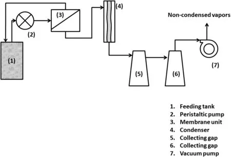
Fig.2.Schematic of MD experimental laboratory setup.
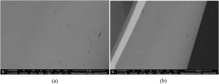
Fig.3.SEM images for M1.(a)and(b)present surface morphology tested at 30 μm-4000× mag,and 50 μm-2000× mag respectively.
In the present work,membranes were prepared using phase inversion method.In this process,a polymer is transformed from a liquid or soluble state to a solid state.Tetrahydrofuran and N-Methyl-2-pyrrolidone were used to solubilize the polymer.Phase inversion technique was used to prepare the polymer solution and was conducted according to the following steps.The first step considered choosing the appropriate materials required to achieve the desired specifications of the prepared membranes.In the second step,the polymer solution was prepared by mixing polymers with solvents at room temperature.Table 1 shows the composition of each prepared polymer solution.In the third step,this solution was carefully poured into a glass casting support using doctor blade for obtaining required membranes thickness of30–40 μm.Finally,aftera partialevaporation of the solvent,the cast film was immediately immersed into the coagulation bath(water)in order to remove any residual solvent and produce a thin film of the polymeric membrane.The whole process is illustrated in Fig.1.
2.3.Characterization methods
Scanning electron microscope(SEM)was used to inspect the crosssection and surface morphology of membranes by using Quanta FEG 250 SEM.The dried samples were coated by gold sputtered for producing electric conductivity.
Fourier Transform Infrared Spectroscopy(FTIR)was used to analyze organic materials and certain inorganic materials,since it has the ability to provide specific information about chemical bonding and molecular structure.The Jasco FTIR-4100 spectroscopy was applied to investigate the chemical bonding and molecular structure of the prepared membranes.
Mechanical properties of PVC/PVP membranes were measured by the Lloyd Lr10K,screw-driven testing machine fitted with a 1 kN load cell with a bespoke 30 mm diameter testing head.The cross head speed was 5 mm·min-1.Tensile strength,Young modulus,and elongation at break are reported as the average value of several measurements.
The membrane porosity was found by dividing the pores volume by the total volume of the porous membrane.The pore size distribution,pore volume and pore area ofthe prepared membranes was determined through using a Hg porosimeter(Type No.9810).
The contact angle of membranes was measured using a Compact video microscope(CVM)manufactured by SDL-UK;the contact time was 10 s with average drop volume 10 μl and each value was averaged from four measurements[13,31].

Fig.4.SEMimages for M2.(a)presents surface and cross-section morphologies tested at30μm-4000×mag respectively.(b)Shows the cross section and surface morphologies determined at 50 μm-2000× mag.
2.4.Flux and salt rejection measurements
The permeability measurements,permeate flux,and salt rejection of the investigated membranes were carried out on vacuum membrane distillation(VMD)system as shown in Fig.2.This system contains flat sheet membrane module contains three openings for feeding,recycling and permeate vapour.The feed from an open feeding tank(10 L)was continuously fed to the membrane module using peristaltic feeding pump.Vacuum pressure was applied using vacuum pump.The feed mixture was heated using thermocuple.Condenser was used as a cooling system to condense the collected vapours.The product was collected using collecting gaps after downstream of the condenser.The prepared membranes were located in stainless steel plate module of 47 mm diameter.In all experiments,the aqueous feed solution of about 10,000 μg·g-1of NaCl in deionized(DI)water was prepared and continuously fed to the membrane module,the other MD parameterѕ remain conѕtant at feed flow rate of 12 ml·s-1,a vacuum pressure of 20,000 Pa and temperature range of 25–45 °C.
3.Results and Discussions
3.1.Membrane characterization by SEM
The top surface,the cross-section and the bottom surface of membranes morphologies were investigated using scanning electron microscope(SEM)as a visualveri fication ofhowthe combination ofPVCand PVP polymers in fluence the membranes morphology.SEM was used to predictthe surface texture,homogeneity and cracks in the prepared composite membranes.Fig.3(a)indicates that M1 is transparent with dense non-porous structure and without any visible cracks.Fig.3(b),exhibits large view spot,confirms the foregoing results for M1.
Fig.4 presents the SEM images of surface and cross section for membrane 2(M2).Fig.4(a)shows that the membrane surface is smooth and pores are uniformly distributed with no sign of visible cracks.Fig.4(b)exhibits thatthe M2 is porous and their pores distribute evenly throughout the membrane surfaces and edges.It is clear that pore sizes through the edge have large sizes in comparison to that of the surface of M2.This can be attributed to the presence of PVP as a blending polymer for preparing composite M2.M2 is the only membrane in this study contained the PVP as additives to PVC polymer.The addition of PVP has the bene fits of improving the membrane performance.Furthermore,this additive is extremely hydrophobic due to the presence of N--C=O bond;this accordingly result in membrane with increased permeability.Hence,the fouling rate is expected to be decreased[22,23].

Fig.5.SEM images for M3.(a)and(b)present surface morphology tested at 30 μm-4000× mag,and 50 μm-2000× mag respectively and(c)Shows the cross section morphology determined at 50 μm-2000× mag.
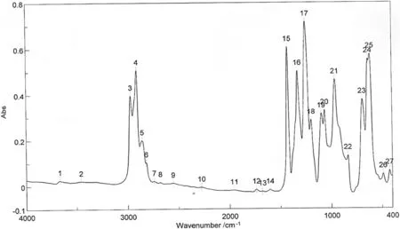
Fig.6.FTIR spectroscopy of M1.
Membrane 3(M3)is prepared without using PVP,but the solvent mixture was formed from THF(82.6%)and NMP(17.4%)instead of using THF only in the case of M1.The percentage of PVC to solvent mixture is 14%to 86%respectively.According to Fig.5(a)and(b),M3 surface is smooth with uniformly distributed pores.In addition,it isnoticed thatthere is no sign ofvisible cracks alloverthe membrane surface.Fig.5(c)indicates that M3 displays continuous homogeneity with more pores in its cross section.Also,it is noticed that the number of pores in M3 surface are larger in size than that of M2.However,M2 is more porous than M3 due to using PVP which leads to uniform pore,where using PVP in polymeric solution increases the polymeric content concentration and produces membrane with small size pores[22–24].
3.2.Membrane characterization by FTIR
Fourier-Transform Infrared(FTIR)was used to study the distribution of functional groups and molecular orientations in the membranes under investigation.The FTIR test was conducted in this study using Jasco FTIR 4100.The FTIR responses for M1 that relate the wave numberand absorption fordifferentpeaksare illustrated in Fig.6.The integrated table with this Figure shows the peaks and their intensities.However,Table 2 listed the peak wavelength,functional groups represented by each beak and its type.The results in the table indicate that M1 is composed only of poly vinyl chloride(PVC).This can be illustrated by the presence of double bonds appear at absorption peaks 21,22,and 23 that correspond to wavelengths of 962,835,and 692 cm-1respectively[24].Moreover,the absorption peak 24 is very small and only absorption peak 25 corresponds to a wave length of 615 cm-1could indicate the presence of chloride in the polymer matrix.This consequently provides the proof that this membrane sample(M1)is composed only of PVC.

Table 2 Infrared absorption of M1resulted by FTIR test
As indicated before,M2 was formed using a blend of PVC and PVP polymers.This can be confirmed by the FTIR responses of this membrane as shown in Fig.7 and Table 3.Besides the functional groups indicate the presence of PVC as previously explained for M1,M2 has functionalgroups indicating the presence ofPVP in its polymeric matrix.This can be illustrated by the presence ofC--N,C=O,and C--Hcontained a bend CH3absorption peaks determined at 1246,1096,and 1427 cm-1respectively as listed in Table 3.The amount of PVC in membrane M1 is higher in comparison to M2 membrane and this can be illustrated by the higher absorption intensity of C--Cl bond in case of membrane M1;0.57 for M1 compared to 0.47 for M2.Itshould be noticed thatboth membrane types(M1 and M2)show absorption peaks of C--Cl bond approximately at the same position of 617 cm-1[24].
It should be noted that M3 was prepared using the same PVC content ofM1(14%PVC and 86%solvent),butin the presence ofa solventmixture of THF and NMP instead of using THF solvent in the case of M1(see Table 1).From FTIR results shown in Fig.8 and Table 4,it is clear that the intensity of absorption peak for C--Cl in the case of M3 is higher compared to its value of 0.57 in the case of M1[24].
3.3.Mechanical characterization
Mechanical behaviors of investigated membranes were measured by Lloyd-Lr10k testing machine at ambient temperature.This test was performed at a crosshead speed of 5 mm·min-1,the load cell of 1 KN for membrane thickness of 40 μm.The mechanical behavior of M1 was not determined.This is because M1 is fragile and cannot withstand to perform such mechanical test.The mechanical properties of M2 and M3 are illustrated in Table 5.Itis observed thattensile strength and elongation at break has lower values in the case of M3(has no PVP polymer)compared to M2 that contains PVP polymer.On the other hand,Young's modulus for M2 is slightly lower than that of M3.Furthermore,the elongation at break value for M2 is four times thatofM3.The aforementioned mechanical behavior indicates that M2 has excellent mechanical properties compared to M3.During operation in the purposes ofsea water desalination or wastewater reclamation,M2 can withstand the difficult operational conditions such as high pressure.Thus,M2 is preferable over M3 in the viewpoint of mechanical behavior.
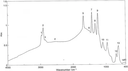
Fig.7.FTIR spectroscopy of membrane M2.
3.4.Membrane porosity and contact angle
It is observed that the evaporation surface area increases with the increase in porosity level of the membrane.This consequently leads to higher permeate fluxes.Moreover,membrane porosity affects the amount of heat loss by conduction[25–27].
The results indicate that M1 was too fragile to perform the porosity test and therefore,there are no results considering the porosity of this membrane.The porosity,pore size and density were measured for membranes 2 and 3.As shown in Table 6,the measured porosity of M2 is 72.79%which is higher than M3.On the other hand,M3 has the lowest porosity of 38.64%as shown in Table 6.It is observed that the porosity of M2 is approximately twice the porosity of M3.Thus,M2 is preferred over M3 and can be applied successfully in membrane distillation processes.Also,the average pore diameter of M2 is twice that of M3;0.0512 μm and 0.0279 μm for M2 and M3 respectively.The increasing of porosity and pore size of M2 can be attributed to the presence of PVP as a blending polymer and pore-former additive with PVC.
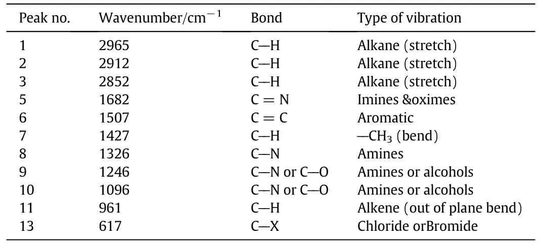
Table 3 Infrared absorption of M2 resulted by FTIR test
Contact angle measurement of membranes is very an important parameter for membrane characterization and indirect indication of the hydrophilicity and flux behavior.Table 7 illustrates the water contact angles of the prepared membranes and membrane wettability.The results indicate that M2 has lowestcontactangle(38±2)°due to addition ofPVP as shown in Table 7 and M1 has highestcontactangle(84±2)°due to using THF as solvent without NMP,which means using mixed solvent and PVP leads to improve hydrophilicity[13,31].The roles of PVP in membrane blend is production ofporous membrane with uniform low size pores and improve the hydrophilic nature of PVC membrane.
3.5.Membrane performance
The porosity and hydrophobicity of the membrane can be used to determine the flux of the membrane.It is expected that the highly porous membrane will give high flux,but the amount of hydrophobicity/hydrophobicity may be a barrier to doing that.So,it is important to investigate the effect of porosity and hydrophobicity/hydrophobicity of the considered membranes on the flux rate.Vacuum membrane distillation process was applied to measure the membrane flux where the synthetic salty water(10000 μg·g-1)entered the housing membrane in a temperature difference between 25 °C and 45 °C with a partial vacuum pressure 0.02 MPa.M1can't withstand during flux determination test and consequently there are no results considering flux through M1.The flux of M2 and M3 were measured according to the following equation:

where J is the penetration flux,kg·m-2·h-1;Q is the permeate quantity,kg;A is the effective area ofthe membrane,m2;t is a time interval,h.The calculated flux of M2 is 8.99 kg·m-2·h-1with permeate flow rate of 0.01558 kg·h-1and membrane effective area of 17.34 × 10⁻⁴m2.However,the calculated flux of M3 is 6.2 kg·m-2·h-1with permeate flow rate of 0.010751 kg·h-1and same membrane effective area of 17.34×10⁻⁴m2.It is clear that the flux of M2 is higher than that of M3.This can be attributed to the higher porosity of M2 compared to M3 porosity,where,the porosity of M2 is approximately the double of M3 porosity value.
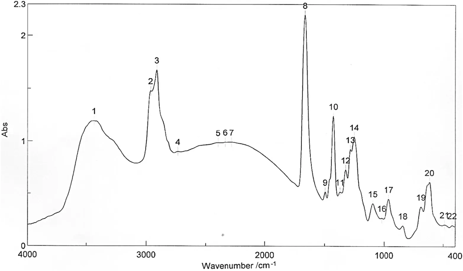
Fig.8.FTIR spectroscopy of membrane M3.
The hydrophobicity results indicate increased membrane wettability and reduced filter pressure.This could be as a result of lower water contact angle of that type of membrane that has a significant effect on the reduction of filter media capillary pressure[13].Besides,it results in an increase of the liquid flow rate and the separation ability of the suspended particles.In the meantime,the biofouling could be greatly eliminated as well as the filter media clogging during the filteration process[23].The polyvinyl chloride(PVC)membrane exhibits a hydrophobic nature and water soluble polyvinylpyrrolidone(PVP)was added into PVC to improve hydrophilicity to membranes,also the addition of PVP in the polymeric solution increased the total concentration of the polymer and formed membrane with small and homogenous pores,that led to improve rejection and flux[28–30].
The membrane distillation process was also applied for measuring the salt rejection for the investigated membranes.The aqueous feed solutions of NaCl were prepared and were continuously fed to the investigated membrane distillation process.The TDS(mainly NaCl)of aqueous feed was 10000 μg·g-1.As mentioned before,M1 is so fragile and cannot be used to measure the salt rejection.The salt rejections of M2 and M3 were calculated according to the following equation:

The calculated salt rejections of M2 and M3 were 97.8%and 98%respectively.It is clear that the two types of membranes give approximately the same salt rejection value of 98%.However,M2 is favored over M3.This is because M2 has better mechanical properties and higher flux than that of M3.
3.6.Comparison with other membranes and expected applications
The mechanical and physical properties of the produced M2 were compared to other types of membranes contained PVC in theircompositions.Asan example,the characteristic ofthe polyvinylchloride and co-polybutadiene-acrylonitrile(PVC/PBA)blend membranes prepared by Islam and co-workers[32]were compared with the corresponding properties of M2 which is composed of a blend of PVC and PVP polymers.The comparison showed that M2 has the same elongation at break value of the PVC/PBA blend.However,the flux of the PVC/PVP blend was better than that of PVC/PBA blend.The porosity test showed that our PVC/PVP membrane pore size is smaller than PVC/PBA blend and this,in turn,will control the application of each type of membrane.Also,SEM results for M2 was compared with the membranes prepared from amphiphilic polyvinyl chloride-gpolyoxyethylene methacrylate(PVC/PVC-G-POEM)graft copolymers and produced by Rajkumar etal.[33].The SEMresults ofourinvestigated membrane(M2)showed more homogeneous and uniform surface with well-distributed pores without any visible cracks compared with the PVC/PVC-G-POEM membranes.It is important to quote that M2 pore size is suitable for MD processes.Thus,M2 can be applied for desalination of sea and brackish water with less fouling problems.After the characterization of our investigated types of membranes,it is obvious that M2 has excellent properties which make it can be used for the purposes of water treatment through MD process.The MD process is competitive for desalination of brackish and sea water.It is also an effective process for removing organic and heavy metals from aqueous solution,from waste water[34].It is important to note that the salt rejection value(98%)of the prepared membranes(M2 and M3)can be increased to reach the salt rejection value of99.3%required to produce drinking waterfromseawater in a single pass by controlling the feed flowrate of the salted water[35,36].
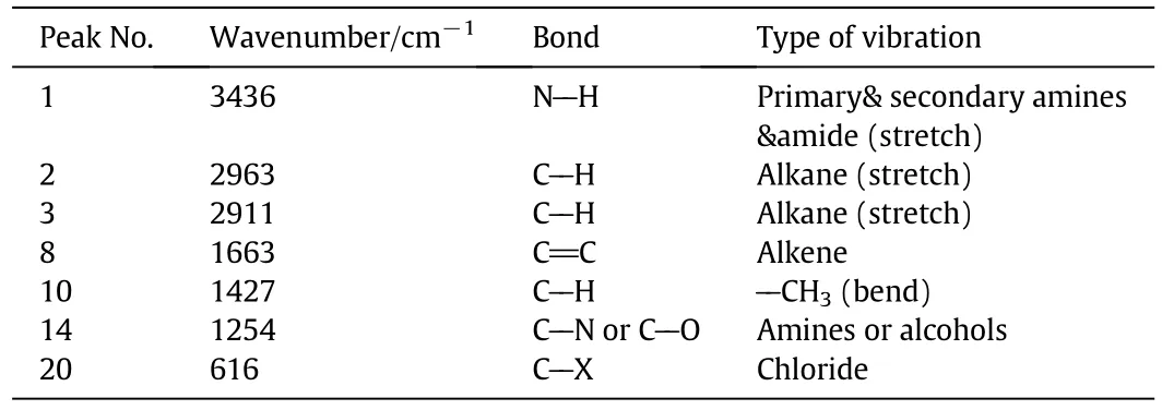
Table 4 Infrared absorption of M3 resulted by FTIR test
4.Conclusions
The presentresearch work provides a new composite membrane for the purpose of water treatment especially the saline water treatment through MD process.The following conclusions can be given from the present work:

Table 5 Mechanical properties of M2 and M3

Table 6 Porosity,pore size and density of M2 and M3
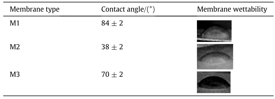
Table 7 contact angle measurement
·Three types of membranes were prepared,namely M1,M2,and M3.The proposed membranes composed of PVC only or PVC/PVP combination that can improve the membrane performance.
·The developed membranes were characterized using scanning electron microscopy(SEM),and Fourier transforms infrared spectroscopy(FTIR).Also,porosity, flux,and salt rejection measurements were conducted using synthetic solutions.
·The SEM results showed that M1 is a dense membrane compared to M2 and M3.This consequently may enhance the salt rejection of M1 if it practically applied without problems.According to SEM results,M2 and M3 surfaces were smooth and pores are uniformly distributed with no sign of visible cracks.
·M3 which was prepared using PVC without the addition of PVP but in the presence of solvent mixture of THF and NMP instead of using THF only as in the case of M1,provides enhancement in the membrane performance.
·Also,M2 is composed of a blend of PVC and PVP polymers.Provides good performance due to the presence of functional groups belongs to PVC and PVP in M2 polymers matrix.
·The porosity and the average pore diameter of M2 are approximately twice the corresponding values of M3 due to the presence of PVP.
·The permeate flux through M2 is higher than thatofM3.This can be attributed to higher porosity and hydrophilicity of M2 compared to M3.
·It is found that M2 and M3 have approximately the same salt rejection percentage of98%.However,M2 is favored over M3 in water treatment purposes due to its better mechanical properties and higher flux.
·The expected application of the developed membranes especially M2 could be directed to the desalination of the sea or brackish water via VMD processes.
References
[1]P.G.Youssef,S.M.Mahmoud,R.KAL-Dadah,Seawater desalination technologies,Int.J.Innov.Sci.Res.4(2015)402–422.
[2]M.M.Shirazi,A.Kargari,A review on applications of membrane distillation(MD)process for wastewater treatment,J.Membr.Sci.Res.1(2015)101–112.
[3]R.Balamurugan,S.Sundarrajan,S.Ramakrishna,Recent trends in nano fibrous membranes and their suitability for air and water filtrations,Membranes 1(2011)232–248.
[4]R.W.Baker,Membrane Technology and Applications,second ed.John Wiley&Sons,Chichester,2004.
[5]H.Strathman,L.Giorno,E.Drioli,An Introduction to Membrane Science and Technology,Institute on Membrane Technology,CNR-ITM at university of Calabria,via P.Bucci 17/C,87036,Rende(CS),Italy,2006.
[6]P.Van de Witte,P.J.Dijkstra,J.W.A.Van den Berg,J.Feijen,Phase separation processes in polymer solutions in relation to membrane formation,J.Membr.Sci.117(1996)1–31.
[7]F.Liu,N.A.Hashim,Y.T.Liu,M.R.M.Abed,K.Li,Progress in the production and modi fication of PVDF membranes,J.Membr.Sci.375(2011)1–27.
[8]M.Khayet,T.Matsuura,J.I.Mengual,M.Qtaishat,Design of novel direct contact membrane distillation membranes,Desalination 192(2006)105–111.
[9]C.Feng,B.Shi,G.Li,Y.Wu,Preliminary research on microporous membrane from F2.4 for membrane distillation,Sep.Purif.Technol.39(2004)221–228.
[10]A.A.Alanezi,H.Abdallah,E.El-Zanati,A.Ahmad,A.O.Sharif,Performance investigation of O-ring vacuum membrane distillation module for water desalination,J.Chem.2016(2016).https://doi.org/10.1155/2016/9378460,9378460.
[11]H.Abdallah,A.El-Gendi,M.Khder,E.El Zanati,Hydrophobic polyethersulfone porous membranes for membrane distillation,Front.Chem.Sci.Eng.9(2015)84–93.
[12]H.Abdallah,A.F.Moustafa,A.A.AlAnezi,H.E.M.El-Sayed,Performance of a newly developed titanium oxide nanotubes/polyethersulfone blend membrane for water desalination using vacuum membrane distillation,Desalination 346(2014)30–36.
[13]M.Shaban,H.AbdAllah,L.Said,H.S.Hamdy,A.Abdel Khalek,Titanium dioxide nanotubes embedded mixed matrix PES membranes characterization and membrane performance,Chem.Eng.Res.Des.95(2015)307–316.
[14]A.Alkhudhiri,N.Darwish,N.Hilal,Membrane distillation:A comprehensive review,Desalination 287(2012)2–18.
[15]Y.Yun,R.Ma,W.Zhang,A.G.Fane,J.Li,Direct contact membrane distillation mechanism for high concentration NaCl solutions,Desalination 188(2006)251–262.
[16]M.Tomaszewska,Membrane distillation—Examples of applications in technology and environmental protection,Pol.J.Environ.Stud.9(2000)27–36.
[17]M.Gryta,In fluence of polypropylene membrane surface porosity on the performance of membrane distillation process,J.Membr.Sci.287(2007)67–78.
[18]S.Bonyadi,T.S.Chung,Flux enhancement in membrane distillation by fabrication of dual layer hydrophilic–hydrophobic hollow fiber membranes,J.Membr.Sci.306(2007)134–146.
[19]K.Y.Wang,T.Matsuura,T.S.Chung,W.F.Guo,The effects of flow angle and shear rate within the spinnereton the separation performance of poly(ethersulfone)(PES)ultra filtration hollow fiber membranes,J.Membr.Sci.240(2004)67–79.
[20]N.N.Li,A.G.Fane,W.S.W.Ho,T.Matsuura,Advanced Membrane Technology and Applications,John Wiley&Sons Inc.,New Jersey,2008.
[21]L.M.Camacho,L.Dumée,J.Zhang,J.de Li,M.Duke,J.Gomez,S.Gray,Advances in membrane distillation for water desalination and puri fication applications,Water 5(2013)94–196.
[22]J.-J.Qin,A high flux ultra filtration membrane spun from PSU/PVP(K90)/DMF/1,2-propanediol,J.Membr.Sci.211(2003)139–147.
[23]A.Saddat,Preparation,Characterization and Performance Optimization of Ultra filtration Membranes Produced with Polymeric and Inorganic Additives,A Major Qualifying ProjectReportSubmitted to the Faculty ofthe Worcester Polytechnic Institute in Partial Ful fillment of the Requirements for the Degree of Bachelor of Science,2011.
[24]Z.Maghsoud,H.N.F.Mohammad,S.S.Madaeni,Preparation of polyvinylchloride membranes from solvent mixture by immersion precipitation,J.Appl.Polym.Sci.131(8)(2014)https://onlinelibrary.wiley.com/doi/10.1002/app.40206/full.
[25]R.T.Huo,Z.Y.Gu,K.J.Zuo,G.M.Zhao,Fouling resistance of PVDF-fabric composite membrane in membrane distillation desalination,Adv.Compos.150-151(2011)334–339.
[26]K.W.Lawson,D.R.Lloyd,Membrane distillation 2.Direct contact MD,J.Membr.Sci.120(1996)123–133.
[27]H.Susanto,Towards practical implementations of membrane distillation,Chem.Eng.Process.50(2011)139–150.
[28]R.Asmatulu,H.Muppalla,Z.Veisi,W.S.Khan,A.Asaduzzaman,N.Nuraje,Study of hydrophilic electrospunnano fiber membranes for filtration of micro and nanosize suspended particles,Membranes 3(2013)375–388.
[29]A.A.Ayse,Improved filtration membranes through self-organizing amphiphilic comb copolymers,Ph.D.Thesis,Massachusetts Institute of Technology,Cambridge,MA,USA,2009.
[30]H.Muppalla,Highly hydrophilic electrospun fibers for the filtration of micro and nanosize particles treated with coagulants,Master Thesis,Wichita State University,Wichita,KS,USA,2011.
[31]H.Abdallah,T.S.Jamil,A.M.Shaban,E.S.Mansor,E.R.Souaya,In fluence of the polyacrylonitrile proportion on the fabricated UF blend membranes'performance for humic acid removal,J.Polym.Eng.(2017).https://doi.org/10.1515/polyeng-2017-0003.
[32]M.A.Islam,R.N.Stoicheva,A.Dimov,An investigation on the deformational properties of porous poly(vinyl chloride)and co-poly(butadiene-acrylonitrile)blend membranes,J.Membr.Sci.118(1996)9–15.
[33]P.Rajkumar,P.Madhumita,H.A.Sung,K.S.Yong,L.Hyung-Keun,H.K.Jong,S.Jung-Suk,Bioinert membranes prepared from amphiphilic poly(vinyl chloride)-gpoly(oxyethylene methacrylate)graft copolymers,Mater.Sci.Eng.C33(2013)1662–1670.
[34]H.MEttouney,H.T.El-Sessouky,R.S.Faibish,P.J.Gowin,Evaluating the economics of desalination,Chem.Eng.Prog.98(2002)32–39.
[35]R.W.Baker,E.L.Cussler,W.Eykamp,W.J.Koros,R.J.Riley,H.Strathmann,Membrane Separation Systems:Recent Developments and Future Directions,Noyes Data Corporation,Park Ridge,1991 276–328.
[36]J.Mallevialle,P.E.Odendaal,M.R.Wiesner,Water Treatment:Membrane Processes,McGraw-Hill,New York,1996.
 Chinese Journal of Chemical Engineering2018年4期
- Chinese Journal of Chemical Engineering的其它文章
- An innovative design of septic tank for wastewater treatment and its performance evaluation:An applicable model for developing countries
- CFD modeling of turbulent reacting flow in a semi-batch stirred-tank reactor☆
- Synergistic and interference effects in coaxial mixers:Numerical analysis of the power consumption☆
- Atomic layer deposition of Al2O3 on porous polypropylene hollow fibers for enhanced membrane performances☆
- Experimental investigation and cost assessment of the salt production by solar assisted evaporation of saturated brine☆
- Equilibrium of liquid-liquid extraction of 2-phenylbutyric acid enantiomers:Experiment and model☆
