Effect of the operation parameters on the Fischer-Tropsch synthesis in fluidized bed reactors☆
Xiaolai Zhang ,Weixin Qian ,Haitao Zhang ,Qiwen Sun ,Weiyong Ying ,*
1 Engineering Research Center of Large Scale Reactor Engineering and Technology,Ministry of Education,State Key Laboratory of Chemical Engineering,East China University of Science and Technology,Shanghai 200237,China
2 State Key Laboratory of Coal Liquefaction and Coal Chemical Technology,Shanghai 201203,China
1.Introduction
Fischer-Tropsch synthesis(FTS)is demonstrated as a feasible and environmentally benign way for production of liquid to fuels from coal,natural gas and biomass via synthesis gas.Also,the synthetic fuels have high quality due to the absence of aromatics,sulfur,and nitrogen compounds[1].It is a strategic alternative technology for liquid fuels and chemical materials in case of oil shortage and more stringent environmental legislation on liquid fuels[2].
Much attention has been paid for the development of FTStechnology in the pastfewyears.The FTS process is ra there xo thermal with a heat of reaction of about 170 kJ·mol-1[3],So,the sufficient capability of the heat removal is a critical point for developing the commercial F-T reactors.Increased temperature results in higher methane production and faster catalyst deactivation due to sintering and coking.In general,there are five main types of commercial F-T reactors are commonly used,which are known as multi tubular fixed-bed reactor(MTFBR),slurry phase reactor(SPR),circulating fluidized-bed reactor(CFBR),fluidized-bed reactor(FBR),and micro channel or micro structured reactors(MR)[4-11].
It is generally considered that the main advantages of the MTFBR are easy scaling-up,less need for expensive demonstration units,and for separation of catalyst and liquid product,lower catalyst attrition and higher catalyst load[12].The big challenge in applying the fixed-bed technology is heat-removal.Krishna and Sie[13,14].mentioned that MTFBR cannot prevent axial and radial temperature profiles near the inlet of the reactor.Fixed-bed technology also imposes limits on the minimum catalyst particle size that can be applied.When the particles are very small,it will lead to a high pressure drop,While the particles are very large,the selectivity and activity will down.A clear advantage of a slurry-phase reactor is the well-mixed liquid phase resulting in nearly isothermal operation[3].Maret to and Krishna[15]showed that back mixing in slurry bubble-column reactors leads to significant decreases in conversion per pass and reactor productivity.CFBR has a much higher capacity than MTFBR and MR,but the circulation of a large amount of catalystresults in considerable compression of the recycle gas associated with capital and operation costs[16].As fluidized beds have excellent heat transfer,easy heat removal and temperature uniformity,the main advantages of FBR are lower operation and constructing costs and higher capacities[9].
Because of the complexity of the FTS process,mathematical modeling and numerical simulation have been a focus of its researches for many years,among which a number of models have been proposed on fixed bed reactors,SPRs and MRs.These model can be roughly divided into three categories:(a)plug flow model[17,18];(b)pseudo-homogeneous models(both 1D[8,19-24]and 2D[5,25]);(c)computational fluid dynamics(CFD)models,with or without the FTS chemistry[11,26-28].However,studies on the simulation of FBRs are seldom reported.Fernandes[29,30]proposed a mathematical model of FBR to describe the effect of several operation parameters on syngas conversion and the distribution of hydrocarbons.In order to simulate the combination of fluidized and fixed bed membrane reactors,a one-dimensional heterogeneous model is made up based on the kinetics of the main reactions,the mass transfer equations and the heat transfer equations.The Sasol R&D group developed a pilot plant for the FTS[31],reporting similar selectivity and higher conversion than those in commercial CFBR.
CFD models are advantageous for the optimization of many complex processes,especially for the gas-solid flow in FRBs with close and complex interactions between the two phases and the heat and mass transfer,etc.The underlying physico chemical processes can be clearly understood through CFD simulation[32-36].The Eulerian-Eulerian models combined with the kinetic theory are the most popular method for engineering simulation of gas-solid flow.The main features of the flows in fluidized beds has been obtained by either laminar or turbulence models[37-40].The turbulent interactions between the solid and the gas phase have been elucidated by several authors[41-43].Recently,the turbulence model enforced in the CFD code MFIX(Multiphase Flow with Inter phase Exchanges)developed by Simonin's group has predicted dilute gas-solid flows under an appropriate boundary conditions reasonably[44-46].
In this work,the FTS process in a three-dimension(3D) fluidized bed reactor was numerically studied aiming to get a better description.Thus,a 3D model coupled with gas-solid momentum,mass and heat transport,and F-T reactions was employed.The operation parameters on the production rates,the temperature distribution and the selectivity were analyzed based on the simulations in this model.
2.Models and Methods
A 3D computational fluid dynamics(CFD)model coupled with FTS reaction which considered the fluid flow,the heat transfer and the mass transfer mechanism was employed in this paper.
2.1.Conservation equations
The gas-solid flow conservation equations is described briefly in Table 1,and more details can be found in[45,47].
2.2.Constitutive correlations
Constitutive correlations are required for closing the governing conservation equations.The gas-phase stress tensor always uses the Newtonian closure.The gas-solid momentum exchange coefficient(i.e.,the inter phase drag coefficient),which is a crucial parameter for the successful simulation,is taken the same as Syamlal et al.[47,48].The solid stress tensor is calculated from the kinetic theory of the granular[49],using two completely different models,for viscous shearing and plastic regimes[47,48],where an algebraic expression of the granular temperature Θmis used.The solid pressure,which considers the normal forces because of particle-particle interactions[47,49-52],includes a kinetic and a collisional term.The shear viscosity of particles is consisted of three parts,including the collision viscosity,the frictional viscosity and the kinetic viscosity[22].
A transport equation for static enthalpy is used to describe the heat flux in gas phase,and in solid phase the heat transfer is considered similar to a continuous phase[53].The inter phase heat transfer resistance is regarded to be associated with the heat transfer coefficient and the temperature difference[54](Table 2).
2.3.Chemical model
There are many different authors proposed the kinetic mechanism during the F-T synthesis,which can be roughly divided into two categories:one is depended on the Langmuir Hinshel wood Hogan Watson(LHHW)model[55,56],while the other one is based on the power law of chemical rate expression[57,58].The mechanism of the Fe-HZSM5 Bifunctional Catalyst proposed by Marvast et al.[58].was adopted in this study.It was supposed that the F-T reaction include CO,H2,CO2,H2O,CH4,C2H4,C2H6,C3H8,n-C4H10,i-C4H10,and C5+species.The following reactions(1)-(8)were considered as dominating F-T reactions.
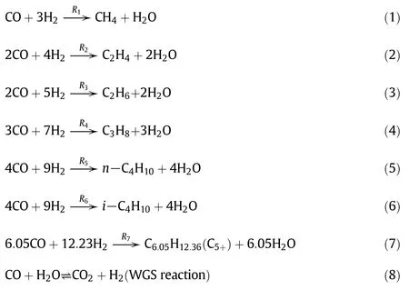
The reactions(1)-(7)are a general form for the rate equations.It is a function of the yield pressures of hydrogen and carbon monoxide,are expressed as:

where P is partial pressure and k is the apparent rate constant.Table 3 presented the kinetic parameters.

Table 1 Conservation equations([45,47])

Table 2 Constitutive relations([45,47])

Table 3 Kinetic parameters for FTS reactions in Eqs.(1)-(7)
The water-gas shift(WGS)reaction is reversible as shown in Eq.(8).The corresponding reaction rate is presented as follows[59]:

For a water-gas shift reaction,KWGSis the equilibrium constant,which is:

3.Simulation Setup
3.1.Reactor geometry
The simulated fluidized bed is described in Fig.1,the inner diameter of which is 30 mm and the height is 500 mm.
The synthesis gas enters from the bottom of the fluidized bed which consists of CO and H2.The Fischer-Tropsch synthesis takes place over the iron based catalyst powder,the effect is reflected on the reaction activation energy.After the reactions,the products and reactant leave from the outlet in the upper part of the reactor.All experiments were carried out at constant pressure conditions.
3.2.Numerical method and parameters
In this study,the MFIX,which is described in Section 2,is used.The discretization of all the governing non-linear partial differential equations is accomplished using the finite volume method on the staggered grid.It is found that the grid size of 1.0 mm×1.0 mm×2.0 mm is sufficient for neglecting the numerical errors due to the grid resolution.

Fig.1.Schematic diagram of the simulated fluidized bed reactor.
To solve the transport and reaction for the model a suitable time step should be used,to ensure the accuracy and stability during the calculation,was 0.00001 s in this study.The segregated solution strategy has been adopted to prevent the iterative divergent.In order to eliminate the pressure-velocity coupling,The traditional SIMPLE method was used.Convective fluxes of the transport equations were all approximated by the Super bee spatial scheme with a secondorder accuracy.Linear discretization for the pressure was adopted.A convergence criterion of 1×10⁻⁵was taken here for all the transport equations.
3.3.Initial and boundary conditions
The gas distribution is assumed to be uniform at the reactor entrance.In order to reach the desired bed expansion,the flow rate was regulated based on the particle size.The inlet gas temperature is fixed ata given value,and the reactor wall was assigned a series of given temperatures in different simulations.The gas phase used a no slip boundary and the solid phase used a free slip boundary.The outlet used a condition of the pressure outlet.Table 4 specifies the parameters in these initial and boundary conditions and the particle properties.
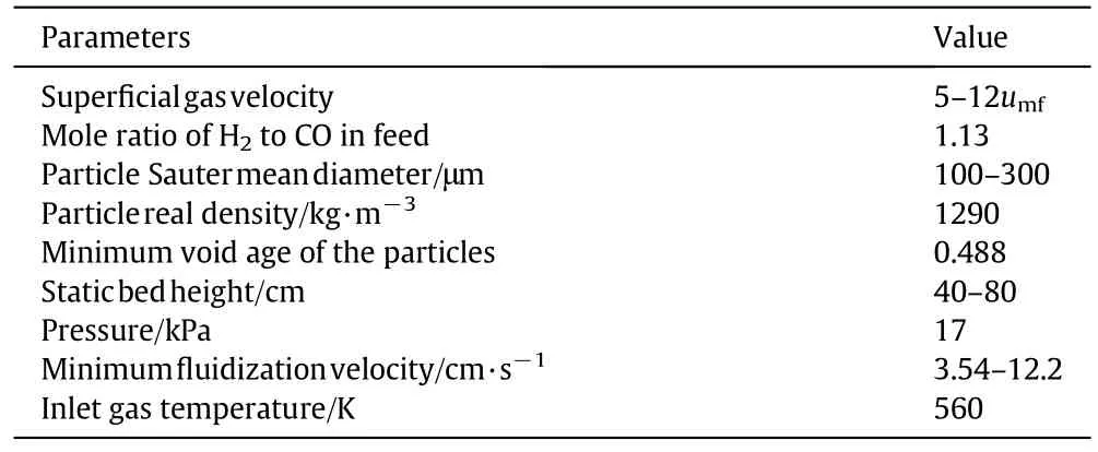
Table 4Operating conditions and material properties of the simulated fluidized bed reactor
4.Results and Discussion
4.1.Model validation
The data of the simulations and the experiments of Rahmati et al.[57]about the methane production rates are plotted in Fig.2.Compared with the experimental data,the average relative error of simulation results is 27.0%,which is in qualitatively agreement to the experiment.Considering the difference of the reaction conditions between the fixed bed reactor in the literature and in the fluidized bed reactor in this study,the simulation results are still reasonable for a qualitative study on the effective of major operation parameters,though quantitative relationships can hardly be found further.

Fig.2.Methane production rates obtained from the simulation and from literature(Rahmati[57]).
4.2.Effect of reaction temperature
During the FT reactions,the surface temperature of the contact mixture must be kept at the required level,and the process is rather exothermal,therefore the cooling mode is vital to the FTS process.As seen in Fig.3(a),the effects of wall cooling temperature(300-556 K)on the production selectivity,which is defined as Xi/Xprodcuction(Xiand Xproductionare the mass flow rate of the ith product and all products leaving the reactor,respectively).The selectivity of C5+decreases quickly with the rise of the cooling temperature,especially when temperature exceeds 450 K.The C5+selectivity is 56.4%at 300 K of the cooling temperature.And to 550 K,it is less than 20%while the light production,especially methane,which is not the product of choice in modern FTS[31]increases when the cooling temperature was raised,especially after it exceeded 450 K.The phenomenon was also observed by Zhu et al.[60].
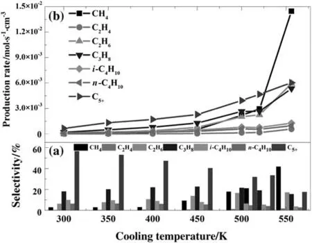
Fig.3.Effect of the cooling temperature on the production selectivity and the production rates(inlet gas temperature=560 K,inlet H2:CO mole ratio=1.13,P=1700 kPa,D p=200 μm).
Fig.4 presents the axial temperature distribution at different cooling temperatures for the gas phase.In general,with the growing of the cooling temperature the average bed temperature in the reactor rises,which causes all production rates to increase with the rising of the cooling temperature(see Fig.3(b)).Based on the Arrhenius equation,the value of the activation energy of Eq.(1)is greater than the activation energy of Eq.(7),the increase of methane production with the temperature could be much faster than the methane production of C5+.This might be the reason that the C5+selectivity sharply decreased when reaction temperature was raised.Other production selectivity has little change with the temperature within 10.0%.It should be noted that the cooling temperature is different from the average bed temperature in corresponding condition.For the cooling temperatures of 450.0 K and 556.0 K,the temperature differences are 45.0 K and 69.3 K,which are 1.22 times of those for the cooling temperatures of 500.0 K and 520 K.Larger temperature differences must lead to more energy loss.
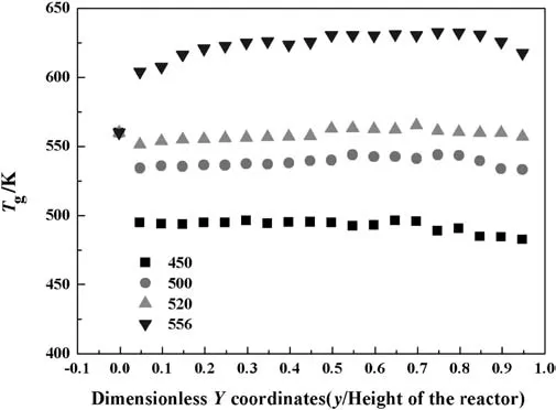
Fig.4.The axial temperature distribution of gas phase at different cooling temperature.(Inlet gas temperature=560 K,inlet H2:CO mole ratio=1.13,P=1700 kPa,D p=200 μm).
4.3.Effect of particle size

Fig.5.Effect of catalyst particle diameter on the production selectivity and the production rates(inlet gas temperature=560 K,inlet H2:CO mole ratio=1.13,P=1700 kPa,bed height=50 cm,cooling temperature=520 K).
The FTS product distributions of the catalyst with the different particle diameters(Dp)are shown in Fig.5.For C5+production,with the rise of the particle diameter the selectivity firstly grows,the maximum value of 33.4%is achieved at 200 μm diameter,which then slightly decreases.While the change trend of the methane production rate is opposite to it.The phenomena can be clearly explained by the axial temperature distribution of the gas phase as plotted in Fig.6.It illustrates that the axial temperature difference is larger for smaller particle,which reaches the largest value of 65.0 K for 100 μm particles,and the lowest value of 7.1 Kfor200μmparticles.The peak value of the temperature for100μm particles is also the maximum at 588.3 K.Because the FTS is a strong exothermic reaction,the small particles tend to aggregate,which leads to poor heat transfer.Meanwhile,smaller particles have higher reaction activity[61].These cause higher solid and gas temperature and uneven temperature distribution.As observed above,when the reaction temperature is high,the C5+production rate is low.This may explain that with the growth of the catalyst particle diameter,the production rates sharply increase and then decrease,as shown in Fig.5(b).
4.4.Effect of superficial gas velocity
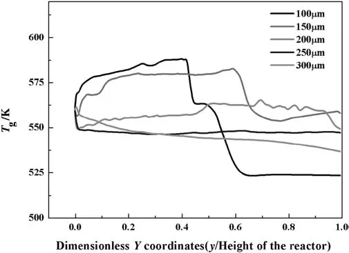
Fig.6.Axial gas temperature distribution with different diameter catalyst particle(inlet gas temperature=560 K,inlet H2:CO mole ratio=1.13,P=1700 kPa,bed height=50 cm,cooling temperature=520 K).
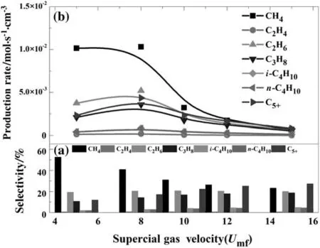
Fig.7.The production selectivity versus catalyst particle diameter(inlet gas temperature=560 K,inlet H2:CO mole ratio=1.63,P=1700 kPa,bed height=50 cm,cooling temperature=520 K).
The effect of superficial gas velocity is given in Fig.7.The superficial gas velocity greatly effects on the production rates.As the super ficialgas velocity is 8 times lower than Umf,the product rates are nearly linear growth when the superficial gas velocity is growing,then decreases.For a fluidized bed reactor,the rate-limiting step is usually decided by mass transport or surface reaction kinetics[62,63].It can be concluded that when the syngas velocity is 8 times lower than Umf,the mass transport limits the process,but when velocity is 8 times over Umf,the limitation is the reaction kinetics.When the syngas velocity is 8 times less than Umf,the C5+selectivity and its production rate show the opposite trend shown in Fig.7(a).
Fig.8 shows the axial gas temperature distribution for different superficial gas velocities.For smaller gas velocity,bed temperature is lower,which may explain the above phenomena.As the superficial gas velocity grows,the gas residence time is shorter,which will reduce the reaction rate and the generation of the heat.Moreover,the heat transfer rate among the gas and solid phase is higher.
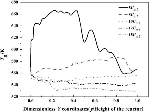
Fig.8.Axial temperature distribution for different superficial gas velocity(inlet gas temperature=560 K,inlet H2:CO mole ratio=1.63,P=1700 kPa,bed height=50 cm,cooling temperature=520 K).
4.5.Effect of bed height
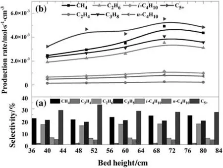
Fig.9.Effect of bed height on the selectivity and rate of the products(inlet gas temperature=560 K,inlet H2:CO mole ratio=1.13,P=1700 kPa,D p=200 μm,superficial gas velocity=8U mf,cooling temperature=520 K).
Fig.9 illustrates the effects of bed height on FTS products.Methane,propane,ethane and C5+production rates slightly increase at the average rates of about 5.0 × 10⁻⁵mol·cm-3·s-1per cm bed height.Higher bed height can provide more particle-surface area,which leads to more heat generation and bed temperature rise.Thus,the selectivity of C5+slightly declines when the bed height is increased,while the methane selectivity has increased accordingly as shown in Fig.8(a).Other production selectivity has less change.
5.Conclusions
The FTS process in a fluidized bed was simulated using the CFD code MFIX for gas-solid flow and heat and mass transfer,together with a reaction kinetic model of Marvast et al.[58].The effect of the operation parameters was investigated.It was found that the effective reaction rate and selectivity depended on the cooling temperature(reaction temperature),the particle diameter,the superficial gas velocity and the bed height.The order of significance of the effects is:the reaction temperature>the particle diameter>the super ficial gas velocity>the bed height.The selectivity of C5+decreased sharply with the rising of the reaction temperature,but less affected by other reaction parameters.The results of the simulations emphasize that temperature control is important.Product yields are dependent on operating conditions especially the temperature.
Generally,the continuum model used in this study agrees reasonably with the experiments in terms of reaction rate and C5+selectivity.However,improvements are required for the model to further investigate the fluidized bed reactors for FTS process.
Nomenclature
Cpspecific heat capacity,kJ·mol-1·K-1
e restitution coefficient
g gravity,m·s-2
gomradial distribution function at contact
H heat transfer,kJ·mol-1
I interaction force representing the momentum transfer,m·s-2
P phase pressure,Pa
Rlthe inter phase mass trans ferterms between the gas and solid phase
T the temperature,K
U velocity component,m·s-1
Xlnmass fraction of n species in the l th phase
α volume fraction
ΔH the heat of reaction,kJ·mol-1
∇⋅q conductive heat flux,kJ·mol-1
δijKronecker Delta
Θmthe granular temperature,K
κ2solid granular conductivity,W·m-1·K-1
μ,μbbulk viscosity,Pa·s
μmshear viscosity,Pa·s
ρ density,kg·m-3
τijsecond-order stress tensor
particle relaxation time,s
collisional time-scale,s
Subscripts
g gas phase
i,jindices to identify vector and tensor components
l liguid phase
m solid phase
WGS water-gas shift
[1]M.R.Rahimpour,M.H.Khademi,A.M.Bahmanpour,A comparison of conventional and optimized thermally coupled reactors for Fischer-Tropsch synthesis in GTL technology,Chem.Eng.Sci.65(23)(2010)6206-6214.
[2]K.J.Woo,S.H.Kang,S.M.Kim,et al.,Performance of a slurry bubble column reactor for Fischer-Tropsch synthesis:Determination of optimum condition,Fuel Process.Technol.91(4)(2010)434-439.
[3]R.M.de Deugd,F.Kapteijn,J.A.Moulijn,Trends in Fischer-Tropsch reactor technology—Opportunities for structured reactors,Top.Catal.26(1-4)(2013)29-39.
[4]P.Narataruksa,S.Tungkamani,K.Pana-Sup pamassadu,et al.,Conversion enhancement of tubular fixed-bed reactor for Fischer-Tropsch synthesis using static mixer,J.Nat.Gas Chem.21(4)(2012)435-444.
[5]X.P.Dai,P.Z.Liu,Y.Shi,et al.,Fischer-Tropsch synthesis in a bench-scale two-stage multitubular fixed-bed reactor:Simulation and enhancement in conversion and diesel selectivity,Chem.Eng.Sci.105(2014)1-11.
[6]G.P.Laan,A.Beenackers,R.Krishna,Multicomponent reaction engineering model for Fe-catalysed Fischer-Tropsch synthesis in commercial scale bubble column slurry reactors,Chem.Eng.Sci.(1999)54.
[7]S.T.Sie,R.Krishna,Fundamentals and selection of advanced Fischer-Tropsch reactors,Appl.Catal.A Gen.186(1)(1999)55-70.
[8]N.Rados,M.H.Al-Dahhan,M.P.Dudukovic,Modeling of the Fischer-Tropsch synthesis in slurry bubble column reactors,Catal.Today 79(2003)211-218.
[9]M.E.Dry,High quality diesel via the Fischer-Tropsch process—A review,J.Chem.Technol.Biotechnol.77(1)(2002)43-50.
[10]L.C.Almeida,O.Sanz,J.D'olhaberriague,et al.,Micro channel reactor for Fischer-Tropsch synthesis:Adaptation of a commercial unit for testing micro channel blocks,Fuel 110(2013)171-177.
[11]M.S.Shin,N.Park,M.J.Park,et al.,Computational fluid dynamics model of a modular multichannel reactor for Fischer-Tropsch synthesis:Maximum utilization of catalytic bed by micro channel heat exchangers,Chem.Eng.J.234(2013)23-32.
[12]J.J.C.Geerlings,J.H.Wilson,G.J.Kramer,et al.,Fischer-Tropsch technology—From active site to commercial process,Appl.Catal.A Gen.186(1)(1999)27-40.
[13]R.Krishna,S.T.Sie,Design and scale-up of the Fischer-Tropsch bubble column slurry reactor,Fuel Process.Technol.64(1)(2000)73-105.
[14]S.T.Sie,R.Krishna,Fundamentals and selection of advanced Fischer-Tropsch reactors,Appl.Catal.A Gen.186(1)(1999)55-70.
[15]C.Maretto,R.Krishna,Modelling of a bubble column slurry reactor for Fischer-Tropsch synthesis,Catal.Today 52(2)(1999)279-289.
[16]B.Jager,M.E.Dry,T.Shingles,et al.,Experience with a new type of reactor for Fischer-Tropsch synthesis,Catal.Lett.7(1)(1990)293-301.
[17]M.R.Rahimpour,S.M.Jokar,Z.Jamshidnejad,A novel slurry bubble column membrane reactor concept for Fischer-Tropsch synthesis in GTL technology,Chem.Eng.Res.Des.90(3)(2012)383-396.
[18]L.C.Almeida,O.Sanz,D.Merino,et al.,Kinetic analysis and microstructured reactors modeling for the Fischer-Tropsch synthesis over a Co-Re/Al2O3catalyst,Catal.Today 215(2013)103-111.
[19]Y.N.Wang,Y.Y.Xu,Y.W.Li,et al.,Heterogeneous modeling for fixed-bed Fischer-Tropsch synthesis:Reactor model and its applications,Chem.Eng.Sci.58(3)(2003)867-875.
[20]M.R.Rahimpour,H.Elekaei,A comparative study of combination of Fischer-Tropsch synthesis reactors with hydrogen-perm selective membrane in GTL technology,Fuel Process.Technol.90(6)(2009)747-761.
[21]M.Bayat,M.R.Rahimpour,B.Moghtaderi,Genetic algorithm strategy(GA)for optimization of a novel dual-stage slurry bubble column membrane configuration for Fischer-Tropsch synthesis in gas to liquid(GTL)technology,J.Nat.Gas Sci.Eng.3(4)(2011)555-570.
[22]N.A.Mamonov,L.M.Kustov,S.A.Alkhimov,et al.,One-dimensional heterogeneous model of a Fischer-Tropsch synthesis reactor with a fixed catalyst bed in the isothermal granules approximation,Catal.Ind.5(3)(2013)223-231.
[23]N.Moazami,H.Mahmoudi,K.Rahbar,et al.,Catalytic performance of cobalt-silica catalyst for Fischer-Tropsch synthesis:Effects of reaction rates on efficiency of liquid synthesis,Chem.Eng.Sci.134(2015)374-384.
[24]N.Moazami,M.L.Wyszynski,H.Mahmoudi,et al.,Modelling of a fixed bed reactor for Fischer-Tropsch synthesis of simulated N2-rich syngas over Co/SiO2:Hydrocarbon production,Fuel 154(2015)140-151.
[25]N.Park,J.R.Kim,Y.Yoo,et al.,Modeling of a pilot-scale fixed-bed reactor for ironbased Fischer-Tropsch synthesis:Two-dimensional approach for optimal tube diameter,Fuel 122(2014)229-235.
[26]J.Na,K.S.Kshetrimayum,U.Lee,et al.,Multi-objective optimization of microchannel reactor for Fischer-Tropsch synthesis using computational fluid dynamics and genetic algorithm,Chem.Eng.J.313(2017)1521-1534.
[27]Y.Li,G.Xie,T.Lei,et al.,A CFD model for gas uniform distribution in turbulent flow for the production of titanium pigment in chloride process,Chin.J.Chem.Eng.24(6)(2016)749-756.
[28]S.Wang,B.Shao,R.Liu,et al.,Comparison of numerical simulations and experiments in conical gas-solid spouted bed,Chin.J.Chem.Eng.23(10)(2015)1579-1586.
[29]F.A.N.Fernandes,E.M.M.Sousa,Fischer-Tropsch synthesis product grade optimization in a fluidized bed reactor,AIChE J.52(8)(2006)2844-2850.
[30]M.R.Rahimpour,H.Elekaei,Optimization of a novel combination of fixed and fluidized-bed hydrogen-per mselective membrane reactors for Fischer-Tropsch synthesis in GTL technology,Chem.Eng.J.152(2)(2009)543-555.
[31]M.E.Dry,Practical and theoretical aspects of the catalytic Fischer-Tropsch process,Appl.Cat al.A Gen.138(2)(1996)319-344.
[32]X.Lan,C.Xu,G.Wang,et al.,CFD modeling of gas-solid flow and cracking reaction in two-stage riser FCC reactors,Chem.Eng.Sci.64(17)(2009)3847-3858.
[33]C.Wu,Y.Cheng,Y.Ding,et al.,CFD-DEM simulation of gas-solid reacting flows in fluid catalytic cracking(FCC)process,Chem.Eng.Sci.65(1)(2010)542-549.
[34]Q.Xue,T.J.Heindel,R.O.Fox,A CFD model for biomass fast pyrolysis in fluidized-bed reactors,Chem.Eng.Sci.66(11)(2011)2440-2452.
[35]K.Papadikis,S.Gu,A.V.Bridgwater,CFD modelling of the fast pyrolysis of biomass in fluidised bed reactors.Part B:Heat,momentum and mass transport in bubbling lf uidised beds,Chem.Eng.Sci.64(5)(2009)1036-1045.
[36]K.Papadikis,S.Gu,A.V.Bridgwater,CFD modelling of the fast pyrolysis of biomass in fluidised bed reactors:Modelling the impact of biomass shrinkage,Chem.Eng.J.149(1)(2009)417-427.
[37]M.J.V.Goldschmidt,J.A.M.Kuipers,W.P.M.Van Swaaij,Hydrodynamic modelling of dense gas- fluidised beds using the kinetic theory of granular flow:Effect of coef ficient of restitution on bed dynamics,Chem.Eng.Sci.56(2)(2001)571-578.
[38]S.Benyahia,H.Arastoopour,T.M.Knowlton,et al.,Simulation of particles and gas flow behavior in the riser section of a circulating fluidized bed using the kinetic theory approach for the particulate phase,Powder Technol.112(1)(2000)24-33.
[39]A.Almuttahar,F.Taghipour,Computational fluid dynamics of high density circulating fluidized bed riser:Study of modeling parameters,Powder Technol.185(1)(2008)11-23.
[40]A.Neri,D.Gidaspow,Riser hydrodynamics:Simulation using kinetic theory,AIChE J.46(1)(2000)52-67.
[41]S.Dasgupta,R.Jackson,S.Sundaresan,Turbulent gas-particle flow in vertical risers,AIChE J.40(2)(1994)215-228.
[42]E.J.Bolio,J.L.Sinclair,Gas turbulence modulation in the pneumatic conveying of massive particles in vertical tubes,Int.J.Multiphase Flow 21(6)(1995)985-1001.
[43]C.M.Hrenya,J.L.Sinclair,Effects of particle-phase turbulence in gas-solid flows,AIChE J.43(4)(1997)853-869.
[44]J.He,O.Simonin,Non-equilibrium prediction of the particle-phase stress tensor in vertical pneumatic conveying,ASME 166(1993)253-263.
[45]R.Garg,J.Galvin,T.Li,Open-source MFIX-DEMsoftware forgas-solids flows:PartI—Veri fication studies,Powder Technol.220(2012)122-137.
[46]S.Benyahia,M.Syamlal,T.J.O'Brien,Evaluation of boundary conditions used to model dilute,turbulent gas/solids flows in a pipe,Powder Technol.156(2)(2005)62-72.
[47]S.Benyahia,M.Syamlal,T.J.O'Brien,Study of the ability of multiphase continuum models to predict core-annulus flow,AIChE J.53.10(2007)2549-2568.
[48]P.C.Johnson,R.Jackson,Frictional-collisional constitutive relations for granular materials,with application to plane shearing,J.Fluid Mech.176(1987)67-93.
[49]C.Lun,S.B.Savage,D.J.Jeffrey,et al.,Kinetic theories of granular flow:Simple shear of inelastic particles and general deformations of nearly elastic particles,J.Fluid Mech.140(1984)223-256.
[50]D.Gidaspow,L.Huilin,Collisional viscosity of FCC particles in a CFB,AIChE J.42(9)(1996)2503-2510.
[51]L.Huilin,H.Yurong,D.Gidaspow,Hydrodynamic modelling of binary mixture in a gas bubbling fluidized bed using the kinetic theory of granular flow,Chem.Eng.Sci.58(7)(2003)1197-1205.
[52]D.G.Schaeffer,Instability in the evolution equations describing incompressible granular flow,J.Differ.Equ.66(1)(1987)19-50.
[53]M.Syamlal,D.Gidaspow,Hydrodynamics of fluidization:Prediction of wall to bed heat transfer coefficients,AIChE J.31(1)(1985)127-135.
[54]D.J.Gunn,Transfer of heat or mass to particles in fixed and fluidised beds,Int.J.Heat Mass Transf.21(4)(1978)467-476.
[55]H.Atashi,F.Siami,A.A.Mirzaei,et al.,Kinetic study of Fischer-Tropsch process on titania-supported cobalt-manganese catalyst,J.Ind.Eng.Chem.16(6)(2010)952-961.
[56]J.Yang,Y.Liu,J.Chang,et al.,Detailed kinetics of Fischer-Tropsch synthesis on an industrial Fe-Mn catalyst,Ind.Eng.Chem.Res.42(21)(2003)5066-5090.
[57]M.Rahmati,M.Mehdi,M.Bargah-Soleimani,Rate equations for the Fischer-Tropsch reaction on a promoted iron catalyst,Can.J.Chem.Eng.79(5)(2001)800-804.
[58]M.A.Marvast,M.Sohrabi,S.Zarrinpashne,et al.,Fischer-Tropsch synthesis:Modeling and performance study for Fe-HZSM5 bifunctional catalyst,Chem.Eng.Technol.28(1)(2005)78-86.
[59]Y.N.Wang,Y.Y.Xu,H.W.Xiang,et al.,Modeling of catalyst pellets for Fischer-Tropsch synthesis,Ind.Eng.Chem.Res.40(20)(2001)4324-4335.
[60]X.Zhu,X.Lu,X.Liu,et al.,Heat transfer study with and without Fischer-Tropsch reaction in a fixed bed reactor with TiO2,SiO2,and SiC supported cobalt catalysts,Chem.Eng.J.247(2014)75-84.
[61]G.Chabot,R.Guilet,P.Cognet,et al.,A mathematical modeling of catalytic milli- fixed bed reactor for Fischer-Tropsch synthesis:In fluence of tube diameter on Fischer Tropsch selectivity and thermal behavior,Chem.Eng.Sci.127(2015)72-83.
[62]F.M.Dautzenberg,M.Mukherjee,Process intensification using multifunctional reactors,Chem.Eng.Sci.56(2)(2001)251-267.
[63]P.Zhang,J.H.Duan,G.H.Chen,et al.,Effect of bed characters on the direct synthesis of dimethyl dichlorosilane in fluidized bed reactor,Sci.Rep.UK 5(2015)1-8.
 Chinese Journal of Chemical Engineering2018年2期
- Chinese Journal of Chemical Engineering的其它文章
- Transport hindrances with electrodialytic recovery of citric acid from solution of strong electrolytes
- Experimental investigation on CO2-light crude oil interfacial and swelling behavior
- Biosynthesis of 4-hydroxyphenylpyruvic acid from L-tyrosine using recombinant Escherichia coli cells expressing membrane bound L-amino acid deaminase☆
- Process development for producing a food-grade glucose solution from rice straws
- Carbon dioxide induced degradation of diethanolamine during absorption and desorption processes
- Biodegradation of natural and synthetic estrogens in moving bed bioreactor
