
A CFD model for predicting the heat transfer in the industrial scale packed bed☆
2018-05-25 19:07:32BaolinHouRenmingYeYanqiangHuangXiaodongWangTaoZhang
Baolin Hou ,Renming Ye ,Yanqiang Huang,Xiaodong Wang*,Tao Zhang
State Key Laboratory of Catalysis,Dalian Institute of Chemical Physics,Chinese Academy of Sciences,Dalian 116023,China
1.Introduction
Packed bed is one of import ant reactors,which has been widely used in the chemical and process industries,for example,the trickled bed,coal gasification,methane catalytic reforming,catalytic combustion and heat exchangers[1,2].Evaluating the heat transfer in packed bed is critical in determining the safe operating condition and optimizing the relevant devices,especially for the strong exothermic process[3,4].In literature,theoretically simulating orexperimentally investigating the energy transport in packed bed attracted many researchers'attentions[5-7].In theory,the traditional lumped-parameter model was often used to evaluate the temperature profile in packed bed in the past,in which the fluid flow was simplified as the plug flow,and the heat transfer was described by the effective thermal conductivity kerand the wall heat transfer coefficient hw[8,9].In fact,many factors need to be considered in predicting the heat transfer in packed bed,for example,the particle shape,the local fluid velocity,the local voidage and the diameterratio between tube and particle.Thus,most of equations dispersed in the literature for representing these two parameters had to be semi-empirical and were obtained by fitting the experimental data of the axial or radial distribution of temperature.To improve the accuracy of model,people included the in fluence factors as many as possible when correlating the relevant parameters[10].However,the simulating results were not significantly improved by incorporating more influencing factorsinto the relevant semi-empirical equations.Until now,a general acceptable model is still not developed.As a result,the expensive pilot plants for commercializing a new reaction processin packed bed stillhave to be built to determine the optimum and safe operating conditions.
The heat transfer in packed bed is that the energy outside the wall exchanges with the packed bed.In this process,the relevant energy is firstly transported to the packed particles and fluid adjacent to the wall.Then,it is transported into the packed bed by the convection and diffusion of fluid and the contacting thermal conductivity of packed particles.Meanwhile,the heat exchange between the fluid and packed particles also occurs.Generally,accurately evaluating the heat transfer strongly depends on the information of fluid velocity field because the fluid is the main energy carrier.Therefore,before analyzing the heat transfer in packed bed,the velocity field firstly needs to be resolved.The packed bed is formed by randomly filling the particles into the reactor tube.The radial distribution of voidage is characterized by the oscillatory behavior due to the wall confine,which will result in the heterogeneous distribution of fluid velocity.Due to the limitation of computer power and the complicated geometrical structure,it was difficult to capture the detailed information of fluid flow in packed bed in the past.To be simple,in the traditional lumped-parameter model,the fluid flow in packed bed was treated as the plug- flow.The effect of fluid dynamics on heat transfer could not be adequately interpreted.Thus,the desired simulating results cannot be obtained by incorporating more factors into the relevant semi-empirical parameters.This kind of theoretic defects of traditional lumped-parameter model made it impossible for being used as a general acceptable model to optimize or design the packed bed.
With the advent of more powerful computers and more sophisticated software,computational fluid dynamics(CFD)also has been employed a powerful tool to investigate the fluid flow and heat transfer in packed bed.CFD models for simulating the packed bed can be categorized into two approaches:high- fidelity simulations[11,12]in which each packed particle is reconstructed and the fluid flow in the gap among the packed particles is solved by Navier-Stokes equations;the porosity-distributed resistance(PDR)[13-16]approach whereby the empty geometry of packed bed is superimposed by the porosity with a radial distribution.Dixon et al.[11] firstly developed the high- fidelity CFD simulations to study the heat transfer in packed bed.In their model,the detailed geometrical information of each packed particle are reconstructed,and the fluid flow is described in the voidage among the packed particles by solving the relevant momentum conservations[11,12].The advantage of this model is that the relevant mechanics of heat transfer can be investigated in detail and the phenomena,which are impossible to be explored by the experiment,can be easily disclosed.Itis important for designing or optimizing the packed bed[11].However,reconstructing the geometric structure and generating the mesh grid become complicated and the demands of computational power increased significantly.Compared to the countless particles involved in each industrial reactor,it is difficult for the current computer power to meet the requirement of applying this model into designing or scaling-up the relevant packed bed.Recently,Bey et al.[16]developed a PDR-CFD model for resolving the fluid velocity field in packed bed,in which the fluid flow was described by the Navier-Stokes equations incorporated with the dimensionless Ergun pressure drop correlations and the radial in homogeneous distribution of porosity,and the turbulence flow due to the randomly packed particles was resolved by the effective fluid viscosity.The relevant simulating results indicated that this model could capture the oscillatory behavior of velocity field in packed bed.Based on this simulating velocity field,Bétteg et al.[17]developed the method of predicting heat trans fer in packed bed.In their model,the effective thermal conductivity coefficient considering the local voidage and fluid velocity was developed by ignoring the temperature difference between two phases and the thermal resistance between the wall and fluid/packed particles.Thus,the energy transported in packed bed can be resolved by solving one differential equation.From the skin-deep understanding,this method simpli fies the process of predicting heat transfers in packed bed.In fact,the accuracy of this model still strongly depends on the effective thermal conductivity from the traditional lumped-parameter model.In addition,some assumptions,for example,ignoring the temperature difference between fluid and packed particles and the influence of fluid mechanical dispersion due to packed particles,and using the coupled boundary condition at the wall,limited this model just to some special cases.
Therefore,in order to meet the general requirement of predicting the heat transfer in the industrial scale packed bed,a general PDR-CFD model is developed in this paper.In this model,the fluid velocity is described by considering the oscillatory behavior of voidage and the effective fluid viscosity[16].Based on this velocity field,the energy transport in fluid is calculated by considering the convection and diffusion incorporated with the fluid mechanical dispersion due to the packed particles.The thermal conductivity among the packed particles is defined and employed to evaluate the relevant energy transport.In addition,with considering the effect of packed particles adjacent to the wall,the heat trans fer coefficient between the wall and fluid/packed particles are developed,respectively.The developed model is employed to simulate the heat transfer process in packed bed from the literature.The good agreements between the simulating results and experimental data indicate that this developed model can be acceptable for analyzing the heat transfer in most packed beds.
2.Model
In this model,the packed bed is superimposed with a radial distribution of porosity.The flow in the voidage among the packed particles is simplified as laminar.The effect of turbulence from the packed particles is evaluated by the effective viscosity,which will be discussed in the following discussion.The relevant equations are expressed as:
Mass conservation:

Momentum conservation:

where,ε is the voidage,μeffis the effective viscosity of fluid with considering the effect of fluid turbulent due to the packed particles,which is expressed as[16]:

where,Dintis the diameter of packed bed.
The forces F are the drag between the fluid and particles,which can be calculated by the Ergun equation[18]:

where,Uiis the superficial velocity of gas,which can be calculated as:

Energy conservation equation:
Gas:

where,h is the enthalpy of gas,Tgis temperature of gas,Shis the heat source from heat transfer between fluid and particles,and can be expressed as:

where,Tsis the temperature of particles,αgis the heat transfer coefficient between fluid and particles,and can be calculated as[19]:

where Cpis the heat capacity of gas,Repis the Reynolds number of particles,and can be calculated as:

where kfis the thermal conductivity coefficient,which includes the effect of the fluid dispersion due to the packed particles,and can be calculated as:

where,kgis the thermal conductivity of gas,and the dispersion coefficients can be calculated as[20,21]:


where the dimensionless number Pemand Sc can be expressed as:
and the parameter δ can be calculated from the following equation:

Solid:

where,keffis the effective conductivity,which can be calculated according to the following section.
3.The Contacting Thermal Conductivity Among Packed Particles
The heat transfer among packed particles is consisted of the conduction and radiation thermal conductivity.Radiation between particles remains small for most applications of packed beds and can be neglected[22].
The contacting thermal conductivity can be calculated from the thermal joint resistance,which is composed of four thermal resistances[23-26]:(1)the macro-contact constriction/spreading resistance RL;(2)the micro-contact constriction/spreading resistance Rs;(3)the resistance of interstitial gas in the micro-gap Rg;(4)the resistance of interstitial gas in the macro-gap RG.Rgis relative small compared to three other components,so it's neglected,here.Therefore,the joint resistance can be described as:

The micro-contact constriction/spreading resistance Rscan be calculated as:

where,H∗is micro-hardness of particles.σ is mean surface roughness height of particles.m is mean surface roughness slope of particles.ksis the thermal conductivity of particles.F is the normal contact force.This force can be a result of one or more of the following:exerted external load on the packed bed,packing under pressure,thermal expansion of the particles and the structural load due to the weight of spheres and so on.In practice,packed bed is a non-homogenous medium of different thermal conductivities corresponding to local variation of contact force.The contact load should be variable at the different location of packed bed.However,in practice,the thermal resistance is evaluated by considering an average contact force to simplify the calculating process.Here,this normal contact force is approximately estimated according to the Ergun equation:

where,Fican be calculated from Eq.(4),Lbedis the length of packed bed.
The macro-contact constriction/spreading resistance RLcan be expressed as:

where,aLis the macro-contact radius,and can be calculated as:

where,parameter β can be written as:

where,the non-dimensional parameters α and κ can be expressed as:

where,the Hertzian contact radius aHcan be calculated as[24]:

where,the effective elastic modulus E′can be written as:

where,E is the Young's modulus,ν is the Poisson's radio.
The resistance of interstitial gas in the macro-gap RGcan be described as:

In the Eq.(26),the relevant parameters can be calculated asS=dp-2ω0+M and ω0=
The gas parameter M is defined as:

where,γ is radio of gas specific heats,Pr=is the Prandtl number of gas,and αTis defined as:

where,Mgis molar mass of gas,and the value of Λ can be found from:
where,Pgis the pressure of gas.Here,P0is set to be 101325Pa,T0=288K,Λ0=64 nm.For Simple Cubic packing(ε=0.476),the effective thermal conductivity due to conduction can be written as:

For Face Centered Cubic packing(ε=0.26),the effective thermal conductivity due to conduction is written as:

And thus,for randomly packing(0.26<ε<0.476),the effective thermal conductivity can be considered as a composite of SC and FCC packing.The effective thermal conductivity due to conduction can be approximately written as:

4.The Radial Distribution of Porosity
In the literature,there are many equations for describing the radial distribution of voidage.Almost all the models were validated by their developed experiment or the results in literature[27-30].Here,the commonly accepted model reported by de Klerk[27]was used:

5.Boundary Conditions
In order to simplify the solution,the fluid is assumed to be homogenously fed into the packed bed.Thus,the boundary condition at the inlet can be expressed as:

According to the assumption,the fluid at the wall is set as the non-slip boundary condition.The energy transported between gas/solid and wall is described as following correlations[31,32],respectively:
The effective wall-to-gas heat transfer coefficient:

The effective wall-to-particle heat transfer coefficient:

where,φis the relative wallcoverage by particles,which is correlated to the voidage:

In this model,the pressure outlet is set to solve the fluid flow.In solving the energy equation,the boundary conditions for the gas and solid at the outlet are set as:

6.Solution Method
Governing Eqs.(1),(2),(6)and(16)for describing the fluid dynamics and heat transfer were solved numerically by ANSYS Fluent 15.0.The momentum and heat transfer equations adopted the second order upwind discrete scheme to improve the computational accuracy.The energy conservation,Eqs.(6)and(16)had been solved by the UDS function of ANSYS Fluent 14.5.The anisotropic dispersion coefficient,as expressed by Eq.(11),which can be evaluated by the matrix of Eq.(10)in the software of ANSYS 14.5.For the voidage distribution in the whole packed bed,the relevantvalue form Eqs.(34)and(35)can be evaluated before solving all equations,and stored in the cell by using the UDM(User De fine Memory)function of software.
In the solution,the relaxation factors for pressure and momentum equation were 0.8 and 0.9,respectively,and the relevant values for other equations were set as default values.The calculation results were considered to be convergent when the residuals for all equations are smaller than 10-9.In addition,the difference for the fields of temperature and velocity between two iteration steps must be smaller than 0.1%.Meanwhile,the difference of mass flow between the inlet and outletis smaller than 0.1%.The effect of mesh grid is checked before each calculation.
7.Experiment
To validate the model proposed in this paper,two experiments performed by Wen and Ding[6]and Thomeo et al.[33]were employed to compare with the CFD results,respectively.The particles in both experiments were randomly packed.
The experiment of Wen and Ding[6]was performed in a vertical tube made of stainless steel with ID 41 mm and a heated length of 1100 mm.The detailed information of experiment can refer to the relevant literature[6].The glass balls with ID 5 mm were randomly packed into the tube.Air was passed through the column.The inlet and wall temperatures were maintained at~20 °C and ~100 °C,respectively.Seven thermocouples located at the center of packed bed at seven axial positions of 30,188,379,579,764,964 and 1062 mm from the inlet were used to measure the axial temperature profiles.Identically,the radial temperature profiles in two axial positions of 579 and 764 mm from the inlet were obtained by five thermocouples.Heat conduction through the stainless-steel supporting rod and arms can be neglected due to their small diameter.According to the description in the literature,the properties of solid particles and fluid and the parameters of packed bed used in simulation are listed in Tables 1 and 2.
The second experiment was conducted by Thomeo et al.[33].Their packed bed was made of stainless steel with an entrance section of 50 mm diameter and 150 mm length and a heating section of 50 mm diameter and 100 mm length.The particles packed into the column were soda-lime glass beads.Air entered the bottom of entrance section at 65 °C,and the wall temperature was fixed at 22 °C.The properties of air,particles and bed are shown in Tables 1 and 3.

Table 1 Air properties in both experiments(Aspen Plus 8.4)
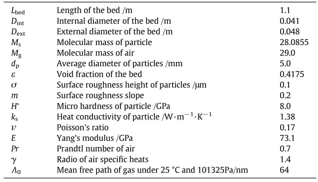
Table 2 Packed bed and particle properties in Wen and Ding's experiment[6]

Table 3 packed bed and particle properties in Thomeo's experiment[33]
8.Results
8.1.The effect of radial distribution of porosity
Before simulating the heat transfer in packed bed by using the CFD model,the inhomogeneous fluid flow needs to be firstly resolved by considering the oscillatory behavior of porosity.The PDR-CFD model is different from the high- fidelity CFD model,in which the detailed structure of porosity cannot be automatically reconstructed by the computer and needs to be described by the relevant statistical expressions as Eqs.(34)and(35).Developing the expressions for describing the oscillatory behavior of porosity in packed bed attracted many researcher's attentions in the past.Recently,de Klerk[27]and Iliuta[34]reviewed the dispersed models in literature.De Klerk[27]made the improvement by correctly predicting the mean voidage.Fig.1 gives four kinds of different radial distribution of porosity.As shown in Fig.1,the porosity adjacent to the wall approaches 1.0 due to the confine of wall.At the center of packed bed,the porosity is approximately equal to the mean voidage.Here,the equation developed by de Klerk[27]is directly employed to investigate the effect of porosity distribution on the heat transfer of packed bed.The effect of other models was not studied in detail because the predicting results by most models are almost the same near the wall,as shown in Fig.1.

Fig.1.Radial distribution of porosity.
Figs.2 and 3 showed comparison for the radial distribution of temperature at the height 0.579 m and 0.764 m between the experimental data[6]and the simulating results with or without considering the effect of radial distribution of porosity.In Fig.2,the voidage in the whole packed bed is defined as a constant with ignoring the radial heterogeneous distribution.As shown in this Figure,the simulating results obviously deviate from the relevant experimental data,especially near the wall,which results from wrongly evaluating the voidage.However,the calculating results can be greatly improved by incorporating the radial heterogeneous distribution of voidage,as represented by Eqs.(34)and(35),into the developed PDR-CFD model,as shown in Fig.3.At the height of 0.764 m,the difference between the simulating results and the experimental data is lightly increased with increasing the Reynold number.Even so,the maximum relative error in the investigated range ofReynold numbers is still lower than 10%,which is generally acceptable for designing or developing the industrial packed bed.However,the identified reasons for the trend of simulating results errors with the improvement of Reynold number is not given because it is complicated by the experimental system errors and the acceptable deviation of equations for the radial distribution of porosity from the relevant true values.
8.2.The effect of fluid dispersion

Fig.2.a.Comparison for the radial distribution of gas temperature between the experimental data[6]and simulating results with using the mean bed porosity.b.Comparison for the radial distribution of gas temperature between the experimental data[6]and simulating results with using the mean bed porosity.
When a fluid flows through the bed packed with inert particles,the dispersion of fluid can be observed as the consequence of combining the molecular diffusion and convection of fluid among the packed particles.In order to resolve the fluid flow in the complicated geometrical structure of packed bed,the method of volume or spatial averaging has to be used because the detailed structure of packed bed is complicated and just some statistical properties can be evaluated.Thus,the transverse and longitudinal dispersion coefficient at the macroscopic level are correlated based on the Fick's law.Since the fluid dispersion in packed bed was studied in 1950s,the numerous correlating equations could be found in literature.Recently,the Delgado's equations[20,21]developed by fitting most of experimental data in literature can give the satisfied agreement between the calculating results and experimental data,as denoted by Eqs.(11)and(12).
According to the Delgado's description,generally,the longitudinal dispersion coefficient is five times greater than the transverse dispersion coefficient when the Reynold number is larger than 10.For the Reynold number smaller than 1,the transverse and longitudinal dispersion coefficient is close to the molecular diffusion.This is verified by checking the effect of dispersion coefficient on the radial distribution of temperature,which can be ignored compared to the longitudinal dispersion coefficient.Therefore,the effect of fluid dispersion on the axial distribution of temperature is just given in this paper,as shown in Figs.4 and 5.Comparing Figs.4 and 5,we can conclude that considering the fluid dispersion can improve the developed PDR-CFD model for simulating the temperature profile in packed bed,especially at the outlet.
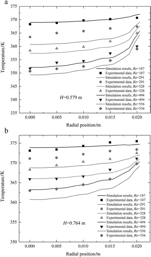
Fig.3.a.Comparison for the radial distribution of gas temperature between the experimental data[6]and simulating results with employing Eqs.(34)and(35)to resolve the radial distribution of porosity.b.Comparison for the radial distribution of gas temperature between the experimental data[6]and simulating results with employing Eqs.(34)and(35)to resolve the radial distribution of porosity.

Fig.4.Comparison for the axial distribution of gas temperature between the experimental data[6]and simulating results without considering the effect of fluid dispersion.
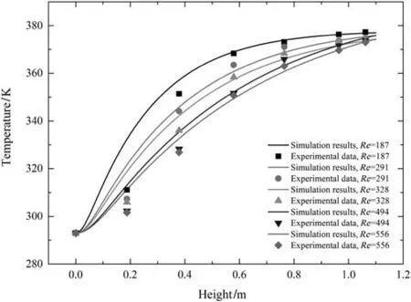
Fig.5.Comparison for the axial distribution of gas temperature between the experimental data[6]and simulating results with considering the effect of fluid dispersion.
8.3.The effect of boundary conditions at the wall
For evaluating the temperature profile in packed bed based on the PDR-CFD model,it is critical to accurately predict the energy transported through the wall by employing the appropriate boundary condition.According to the description for the radial distribution of porosity,the voidage adjacent to the wall approaches to 1,as shown in Fig.1.Thus,the heat transfer coefficient between fluid and wall of packed bed can be evaluated by solving the laminar fluid flow under the Non-slip condition for momentum equations and coupled boundary for energy equations.The contacting thermal conductivity between the packed particles and wall can be ignored.In Fig.6,comparison for the radial distribution of temperature between the simulating results and the experimental data is given,when the temperature of gas phase is defined as the wall temperature and the heat transfer between the solid and wall is ignored.From this Figure,we can see that the relevant simulating results seriously deviate from the experimental data[6].With increasing the height and Reynold number,the difference between simulating results and experimental data becomes bigger.In Fig.3,the effect of packed particles adjacent to the wall on the heat transfer coefficient between the fluid and wall is evaluated by employing Eqs.(38)and(39)to calculate the effect of turbulence due to the particles contacted with the wall.The simulating results showed that the accuracy of developed PDR-CFD model could be obviously improved.Based on the same reasons,the axial distribution of temperature from the simulating results is lower than the relevant experimental data,as shown in Fig.7.However,Using Eqs.(38)and(39)as the boundary conditions,as shown in Fig.5,the simulating results would be closer to the experimental data.According to the above comparison and discussions,the following conclusions can be made that considering the effect of turbulence due to the packed particles contacted with the wall,as given in Eqs.(38)and(39),can improve the accuracy of developed PDR-CFD model.
8.4.The effect of gas effective viscosity
The detailed description of turbulence flow due to packed particles is difficult in using the PDR-CFD model,because the structure of packed particles cannot be resolved by the radial statistical distribution of porosity.To improve the PDR-CFD model,the gas effective viscosity represented as Eq.(3)had been employed to evaluate the effect of turbulence on the velocity field of fluid.The radial distribution of fluid velocity is given based on this model,as shown in Fig.8.Using the effective gaseous viscosity,the velocity in the center of packed bed is higher than that using a constant viscosity,and the reverse is true near the wall.Comparison for the radial and axial distribution of temperature between the experimental data[6]and simulating results from considering the effective gaseous viscosity are given in Figs.9 and 10,respectively.The good agreement can be found.Compared with the simulating results from Figs.3 and 5,the improvement of including the effective gaseous viscosity is negligible.Thus,it can be concluded that the gaseous turbulence due to the packed particles can be ignored in our developed PDR-CFD.The relevant reasons will be given in the following discussion.

Fig.6.a.Comparison for the radial distribution of gas temperature between the experimental data[6]and simulating results with the coupled boundary at wall and ignoring heat transfer between the solid and wall.b.Comparison for the radial distribution of gas temperature between the experimental data[6]and simulating results with the coupled boundary at wall and ignoring heat transfer between the solid and wall.
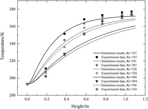
Fig.7.Comparison for the axial distribution ofgas temperature between the experimental data[6]and simulating results with the coupled boundary at wall and ignoring heat transfer between the solid and wall.

Fig.8.Comparison for the radial distribution of velocity magnitude between using the effective gaseous viscosity and using a constant viscosity.

Fig.9.Comparison for the radial distribution of gas temperature between the experimental data[6]and simulating results with using the effective gaseous viscosity Eq.(3).
In addition,the experimental data in the literature[33]are also employed to further validate this optimized model,in which the effective gaseous viscosity described by Eq.(3),the radial distribution of porosity resolved by Eqs.(34)and(35),the fluid dispersion represented as Eqs.(11)and(12)and the heat transfer of fluid and solid at the wall given as Eqs.(38)and(39)are included.The comparison for the radial distribution of temperature and the outlet temperature between the simulating results and the experimental data under the different operating conditions are given.The good agreement,as shown in Figs.11 and 12,indicated again that the developed PDR-CFD model can be used as a general method to simulate the heat transfer in packed bed.
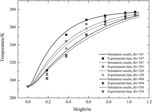
Fig.10.Comparison for the axial distribution of gas temperature between the experimental data[6]and simulating results with using the effective gaseous viscosity Eq.(3).

Fig.11.Comparison for the radial distribution of temperature at the outlet between the simulating results and experimental data[6]for d p=0.9 mm and G=0.76 kg·m-2·s-1.
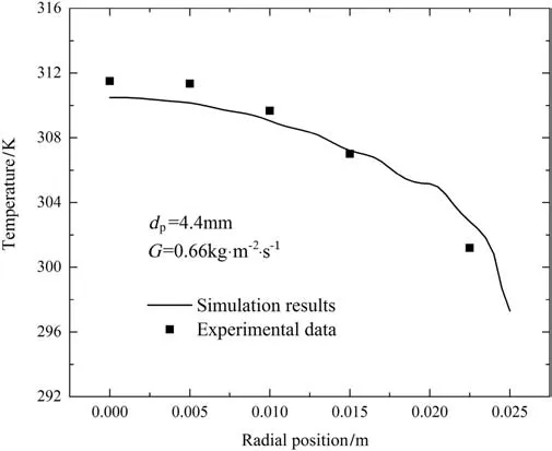
Fig.12.Comparison for the radial distribution of temperature at the outlet between the simulating results and experimental data[6]for d p=4.4 mm and G=0.66 kg·m-2·s-1.
9.Discussion
Predicting the heat transfer in packed bed attracted many attentions since it is important for designing or optimizing the catalytic reactor of packed bed in the chemical industry.In the past,the method of predicting the axial or radial distribution of temperature mainly depended on the semi-empirical effective heat transfer coefficient,which was obtained by fitting the experimental data based on some basic theoretical analysis[7,35,36].In order to meet the requirement of designing the relevant reactors,the effective heat transfer coefficient was correlated by considering the factors as many as possible,for example,the fluid velocity and dispersion due to the packed particles,the thermal conductivity and radiation in the fluid and solid phase,the physical property of solid particle and the packing mechanicals[36].From the theoretical viewpoint,reducing such a complex process into one effective parameter must lead to some deviations from the experimental results in most of cases due to some over-simple assumptions,such as,using the plug- flow model to describe the fluid flow among the randomly packed particles,ignoring the temperature difference between the fluid and solid and the radial axial distribution of voidage.However,in our developed PDR-CFD method,contrary to the conventional model,the heat transfers in the fluid and solid are individually evaluated.The mechanics of heat transfer in each phases are described,respectively.Thus,the effect of fluid flow,dispersion and the thermal conductivity on heat transfer can be evaluated by solving the energy transported equations in the fluid and solid phases,respectively.This method is to decompose a complex process into several relative easily described processes,which sat is fies the nature of analyzing some complex processes.
In this paper,the PDR-CFD model is developed,in which the statistical expressions for the radial distribution of porosity are employed to describe the oscillatory behavior of voidage resulting from the confine of wall.According to the simulating results,it is confirmed the radial distribution of voidage is critical for simulating the heat transfer in the industrial packed bed by employing the developed PDR-CFD model,as shown in Figs.2 and 3.However,in most of statistical equations,as shown in Fig.1,the voidage near the wall is equal to 1.Based on the theoretical analysis,the heat transfers between the wall and packed bed could be predicted just by using the coupled boundary at the wall,as shown Fig.6.In practice,the heat transfer coefficient close to the wall is bigger than the theoretical value evaluated by solving the laminar flow at the wall,which results from the influence of turbulence flow due to the packed particles contacted with the wall.In this paper,we employed the Eqs.(38)and(39)to describe the boundary conditions at the wall,in which the contacting thermal conductivity between the wall and packed particles and the influence of turbulence on the heat transfer between the fluid and wall are included.Comparing for the simulating results between Figs.3 and 6,the boundary conditions used in this paper can improve the developed PDR-CFD model.
The mechanical dispersion of fluid due to the packed particles in the packed bed has been widely studied in the literature.The general conclusion can be expressed that the longitudinal dispersion coefficient is five times than the transverse dispersion coefficient when the Reynold number is larger than 10.For the Reynold number smaller than 1,the transverse and longitudinal dispersion coefficient is close to the molecular diffusion.In this paper,the influence of transverse and longitudinal dispersion coefficient on the heat transfer in the packed bed is investigated.The simulating results showed that the influence of transverse dispersion coefficient can be ignored in our studied cases and considering the influence of longitudinal dispersion coefficient can improve the simulating results for the axial distribution of temperature in the packed bed,as shown Figs.4 and 5.In addition,in order to resolve the influence of fluid turbulence due to the packed particles,the effective viscosity was developed in literature[16].Based on the simulating results given in Fig.8,the radial distribution of fluid velocity is lightly affected by the effective fluid viscosity.The relevant improvement on the radial and axial distribution of temperature can be ignored,as shown in Figs.9 and 10.In fact,the influence of fluid turbulence due to the packed particles on the heat transfer coefficient can be categorized into two kinds,for example,the dispersion of fluid and heat transfer between the fluid and the solid.The former had been considered by using Eq.(11)and(12)in solving the energy transported in fluid.The latter is included by the heat transfer coefficient between the fluid and the solid,as given in Eq.(8).Therefore,in using the developed PDR-CFD model,the influence of effective viscosity due to the packed particles can be ignored in predicting the heat transfer in packed bed.
10.Conclusions
A general PDR-CFD model for simulating the heat transfer in packed bed was developed in this paper,in which the contacting thermal conductivity among packed particles and the heat transfer coefficient between the wall and fluid/packed particles were given.Two experiments from the literature were employed to validate the relevant model.The good agreement between the simulating results and experimental data indicated that the developed model can be generally acceptable for designing and optimizing the packed bed.
In this model,the fluid velocity field among randomly packed particles is resolved by considering the radial inhomogeneous distribution of porosity and the effective fluid viscosity.Thus,the energy transport in packed bed can be described by solving energy conversion differential equations in two phases,respectively,which means that the temperature profiles in packed bed can be evaluated without using any adjustable semi-empirical effective thermal conductivity parameters from fitting the experimental data.This improves the general applicability of developed model.
In addition,the simulating results confirmed that considering the radial inhomogeneous distribution of porosity in packed bed was critical for using the developed PDR-CFD model to predict the temperature profile in the industrial scale packed bed.Adjacent to the wall,the heat transfer can be intensified by the packed particles contacted with the wall,which should be considered in evaluating the temperature profile in packed bed.The coupled temperature boundary condition at the wall would underestimate the relevant heat transfer coefficient.The effect of fluid effective viscosity could be ignored in simulating the heat transfer of packed bed.Considering the fluid mechanical dispersion due to the packed particles can improve the performance of developed model.
Nomenclature
aHradius of Hertzian contact,m
aLradius of macro-contact,m
Cpthermal capacity of gas,J·kg-1·K-1
D effective diffusion coefficient of gas,m2·s-1
Dextthe external diameter of packed bed,m
Dithe dispersion coefficient at x,y direction of Cartesian coordinates,i=x,y
Dintthe internal diameter of packed bed,m
dpmean diameter of particles,m
E Young's modulus,Pa
E′ effective elastic modulus,Pa
F normal contact force,N
Fithe drag force between gas and solid,N·m-3
H∗the mean micro hardness of particles,m
h enthalpy of gas,W·kg-1·K-1
hwgheat transfer coefficient between gas and wall,W·m-2·K-1
hwpheat transfer coefficient between particles and wall,W·m-2·K-1
keffthe effective thermal conductivity of packed beds,W·m-1·K-1
kfthermal conductivity coefficient of fluid,W·m-1·K-1
kgthermal conductivity coefficient of gas,W·m-1·K-1
ksthermal conductivity coefficient of solid or particles,W·m-1·K-1
kFCCthe effective thermal conductivity of Face Centered Cubic packing beds,W·m-1·K-1
kSCthe effective thermal conductivity of Simple Cubic packing beds,W·m-1·K-1
Lbedthe length of bed,m
M gas parameter,m
Mgmolecular mass of gas
Msmolecular mass of solid
m mean absolute surface slope
Nug-wthe gas to wall non-dimension Nusselt number
Nup-wthe particle to wall non-dimension Nusselt number
P parameter used to calculate radius of macrocontact
PeLaxial dimensionless Peclect number
Pemnon-demensional Peclect number
PeTradial dimensionless Peclect number
Pr Prandtl number
Pgpressure of gas,Pa
P0pressure of atmosphere under 101325Pa and 25°C,Pa
p parameter used in Eq.(11)
R radius of packed bed
RGthe resistance of interstitial gas in the macro-gap,K·W-1
Rgthe resistance of interstitial gas in the micro-gap,K·W-1
Rjjoint thermal resistance,K·W-1
RLthe macro-contact constriction/spreading resistance,K·W-1
Rsthe micro-contact constriction/spreading resistance,K·W-1
Repparticle Reynolds number
r radial position of packed bed
Shheat source from heat transfer between fluid and particles,W·m-3
Sc dimensionless Schmidt number
Tgtemperature of gas,K
Tstemperature of solid or particles,K
Twtemperature of the wall,K
T0atmosphere temperature,288 K
Uisuperficial velocity,m·s-1
u0inlet velocity,m·s-1
α non-dimensional parameter
αgheat transfer coefficient between gas and particles,W·m-2·K-1
αTthermal accommodation coefficient
γ ratio of gas specific heats
ε the voidage of the packed bed
ε the average voidage of the packed bed
εbporosity in the bulk region of the packed bed
κ non-dimensional parameter
Λ mean free path of gas,m
Λ0mean free path of gas under 1 atm and 288 K,m
μeffthe effective viscosity of fluid,Pa·s
μ viscosity of gas,Pa·s
ν Poisson's ratio
ρfdensity of gas,kg·m-3
σ mean surface roughness height,m
τ tortuosity
φ the relative wall coverage of particles
[1]Y.L.Ding,Y.R.He,N.T.Cong,W.Yang,H.S.Chen,Hydrodynamics and heat transfer of gas-solid two-phase mixtures flowing through packed beds a review,Prog.Nat.Sci.18(2008)1185-1196.
[2]G.M.Karthik,V.B.Vivek,Effect of particle shape on fluid flow and heat transfer for methane steam reforming reactions in a packed bed,AIChE J.(2016)http://dx.doi.org/10.1002/aic.15542.
[3]M.Nijemeisl and,A.G.Dixon,CFD study of fluid flow and wall heat transfer in a fixed bed of spheres,AIChE J.50(2004)906-921.
[4]A.Guardo,M.Coussirat,M.A.Larrayoza,F.Recasensa,E.Egusquizab,In fluence of the turbulence model in CFD modeling of wall-to- fluid heat transfer in packed beds,Chem.Eng.Sci.60(2005)1733-1742.
[5]T.Estevan,J.P.Roger Spitz,V.M.Broyer,M.Timothy,Packed-bed reactor for short time gas phase ole fin polymerization:heat transfer study and reactor optimization,AIChE J.58(2012)256-267.
[6]D.S.Wen,Y.L.Ding,Heat transfer of gas flow through a packed bed,Chem.Eng.Sci.61(2006)3523-3542.
[7]A.G.Dixon,Thermal resistance models of packed-bed effective heat transfer parameters,AIChE J.31(1985)826-834.
[8]W.van Antwerpen,C.G.du Toit,P.G.Rousseau,A review of correlations to model the packing structure and effective thermal conductivity in packed beds of mono-sized spherical particles,Nucl.Eng.Des.240(2010)1803-1818.
[9]Y.Demirel,R.N.Sharma,H.H.Al-Ali,On the effective heat transfer parameters in a packed bed,Int.J.Heat Mass Transf.43(2000)327-332.
[10]N.Zobel,F.Behrendt,Transient heat transfer in packed beds:the significance of the history term,Int.J.Heat Mass Transf.51(2008)3816-3824.
[11]A.G.Dixon,M.Ertan Taskina,M.Nijemeisl and,E.Hugh Stittb,Wall-to-particle heat transfer in steam reformer tubes:CFD comparison of catalyst particles,Chem.Eng.Sci.63(2008)2219-2224.
[12]D.J.Robbins,M.Samir El-Bachir,L.F.Gladden,R.Stewart Cant,E.von Harbou,CFD modeling of single-phase flow in a packed bed with MRI validation,AIChE J.58(2012)3904-3915.
[13]A.Atta,S.Roy,K.D.P.Nigam,Prediction of pressure drop and liquid holdup in trickle bed reactorusing relative permeability conceptin CFD,Chem.Eng.Sci.62(2007)5870-5879.
[14]Y.Jiang,M.R.Khadilkar,M.H.Al-Dahhan,M.P.Dudukovic,CFD of multiphase flow in packed-bed reactors I.k- fluid modeling issues,AIChE J.48(2002)701-715.
[15]Y.Jiang,M.R.Khadilkar,M.H.Al-Dahhan,M.P.Dudukovic,CFD of multiphase flow in packed-bed reactors:II.Results and applications,AIChE J.48(2002)7016-7730.
[16]O.Bey,G.Eigenberger,Fluid flow through catalyst filled tubes,Chem.Eng.Sci.52(1997)1365-1376.
[17]R.Bétteg,M.F.P.Moreira,R.G.Corrêa,J.T.Freire,Mathematical simulation of radial heat transfers in packed beds by pseudohomogeneous modeling,Particuology 9(2011)107-113.
[18]S.Ergun,Fluid flow through packed columns,Chem.Eng.Process.48(1952)89-94.
[19]K.Jung,R.D.La Nauze,Sherwood numbers for burning particles in fluidized beds,in:D.Kunii,S.S.Cole(Eds.),Fluidization IV Engineering Foundation 1983,pp.427-434.
[20]J.M.P.Q.Delgado,A critical review of dispersion in packed beds,Heat Mass Transf.42(2006)279-310.
[21]J.R.F.Guedes de Carvalho,J.M.P.Q.Delgado,The effect of fluid properties on dispersion in flow through packed beds,AIChE J.49(2003)1980-1985.
[22]M.M.Yovanovich,E.E.Marotta,Thermal spreading and contact resistances,in:A.Bejan,D.Kraus(Eds.),Heat Transfer Handbook,John Wiley and Sons Inc.,Hoboken,New York,USA,2003(Chapter 4).
[23]M.Bahrami,M.M.Yovanovich,J.R.Culham,Effective thermal conductivity of rough spherical packed beds,Int.J.Heat Mass Transf.49(2006)3691-3701.
[24]W.van Antwerpen,P.G.Rousseau,C.G.du Toit,Multi-sphere unit cell model to calculate the effective thermal conductivity in packed pebble beds of mono-sized spheres,Nucl.Eng.Des.247(2012)183-201.
[25]X.L.Wang,J.Zheng,H.L.Chen,A prediction model for the effective thermal conductivity of mono-sized pebble beds,Fus.Eng.Des.103(2016)136-151.
[26]O.Bey,G.Eigenberger,Gas flow and heat transfer through catalyst filled tubes,Int.J.Therm.Sci.40(2001)152-164.
[27]A.de Klerk,Voidage variation in packed beds at small column to particle diameter ratio,AIChE J.47(2003)2022-2029.
[28]G.C.Mueller,Prediction of radial porosity distributions in randomly packed fixed beds of uniformly sized spheres in cylindrical containers,Chem.Eng.Sci.46(1991)706-770.
[29]Y.Cohen,A.B.Metzner,Wall effects in laminar flow of fluids through packed beds,AIChE J.27(1981)705-715.
[30]D.Vortmeyer,J.Schuster,Evaluation of steady flow profiles in rectangular and circular packed beds by a variational method,Chem.Eng.Sci.38(1983)1691-1699.
[31]C.H.Li,B.A.Finlayson,Heat transfer in packed beds—a reevaluation,Chem.Eng.Sci.32(1977)1055-1066.
[32]R.Q.Zhang,H.R.Yang,J.F.Lu,Y.X.Wu,Theoretical and experimental analysis of bed-to wall heat transfer in heat recovery processing,Powder Technol.249(2013)186-195.
[33]J.C.Thomeo,C.O.Rouiller,J.T.Freire,Experimental analysis of heat transfer in packed beds with air flow,Ind.Eng.Chem.Res.43(2004)4140-4148.
[34]I.Iliuta,M.Hamidipour,D.Schweich,F.Larachi,Two-phase flow in packed-bed microreactors:experiments,model and simulations,Chem.Eng.Sci.73(2012)299-313.
[35]S.Yagi,D.Kunii,Studies on effective thermal conductivities in packed beds,AIChE J.3(1957)373-381.
[36]A.G.Dixon,D.L.Cress well,Theoretical prediction of effective heat transfer parameters in packed beds,AIChE J.25(1979)663-676.
 Chinese Journal of Chemical Engineering2018年2期
- Chinese Journal of Chemical Engineering的其它文章
- Surface chemical characterization of deactivated low-level mercury catalysts for acetylene hydrochlorination☆
- Insight into fouling behavior of poly(vinylidene fluoride)(PVDF)hollow fiber membranes caused by dextran with different pore
- Protein adsorption onto diethylaminoethyl dextran modi fied anion exchanger:Effect of ionic strength and column behavior☆
- Gas emission source term estimation with 1-step nonlinear partial swarm optimization-Tikhonov regularization hybrid method☆
- Dissolution of antibiotics mycelium in ionic liquids:Performance and mechanism☆
- Kinetic studies on extra heavy crude oilupgrading using nanocatalysts by applying CFD techniques☆