Study on swarf when sawing granite with diamond wire
, , ,
(Institute of Manufacturing Engineering, Huaqiao University, Xiamen 361021, China)
Diamond wire cutting technology was first used in quarries from which soft stones, including marbles, were extracted. Hence, diamond wire saws are widely used in both quarries and block processing plants to cut marble. Diamond wire saws were first used to extract hard stone, such as granite, gneiss, and diorites, from quarries, in the 1980s. Since then, with the development of diamond-wire cutting machines and diamond wire, diamond wire technology has become the tool of choice in hard-rock quarrying. This technology has significantly improved the production rate and overall efficiency of cutting[1-2].
Unlike circular sawing and wheel grinding, diamond wire sawing displays the following common machining characteristics.
Longcuttingarc. The contact length between the wire and the workpiece is several meters in block processing plants and dozens of meters in quarries. These lengths are hundreds or thousands of times longer than that of the traditional circular sawing arc, as shown in Fig. 1.
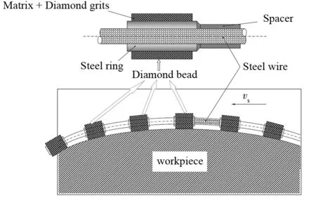
Fig. 1 Illustration of the diamond wire sawing
Flexiblecuttingmode. Diamond wire is more flexible than circular saw blades and grinding wheels. Thus, it can be bent during cutting, because of the elasticity of the twist steel wire, as illustrated in Fig. 1. The degree of bending is closely related to the cutting feed rate. Diamond beads retreat when the cutting force is too strong. As a result, in this flexible cutting mode, violent collision between diamond grains and workpiece is prevented.
To improve sawing performance and reduce cost much research has focused on the machinability of natural stone and on development of efficient tools for granite sawing. BUTLER-SMITH et al. evaluated the performance of individual beads using an apparatus that was specially designed for bead wear and friction testing[3]. OZCELIK et al. optically investigated the effects of the structure of diamond beads and rock types on the wear of diamond beads during cutting[4]. These studies provided fundamental knowledge regarding bead wear in sawing. JAIN et al. also numerically predicted the cutting performance of diamond wire saws, in marble quarrying, using a neural network approach[5]. The effects of machining parameters have also been investigated in the diamond wire sawing of rock, including wire speed, feed rate, cutting length, and segment diameter[6-7]. Although the previous studies provide important insight regarding machining processes and the tool wear mechanism during wire sawing, the prevailing mechanisms of swarf formation have not been clarified thoroughly and quantified. Moreover, the full potential of this process is limited by the lack of a fundamental and systematic understanding of the material removal mechanism.
This paper reports our recent studies on the characteristics and formation mechanism of swarf in granite-wire sawing. The sawing tests are performed with a specially developed apparatus, which utilizes a steel wire impregnated with diamond beads. Swarf is collected from different areas along the sawing arc during the wire sawing of three granites. Furthermore, the particle size distribution (PSD) and the morphology of the sawn swarf are investigated systematically. Finally, the swarf formation mechanism is discussed.
1 Experimental conditions
The wire-sawing experiments were conducted at a spindle power of 5.5 kW, as presented in Fig. 2. The diamond wire used in the experiments was specially designed for granite and is 5.5 m long. The maximum wire speed is 45 m/s and the spacing of the guide wheel 0.8 m. Wire tension was maintained at 1.5 kN, for all experiments, to ensure that the wire remained almost straight (without apparent bowing) during sawing.Thirty-seven abrasive beads were fixed to the wire per meter length. The cylindrical diamond bead had a diameter of 10.5 mm and a length of 7.6 mm. It contained diamond abrasives with mesh sizes of 40/50 and 30/40 (US standard) at 23.25% and 6.75% volume percent concentrations, respectively. The diamond beads were dressed by gently rubbing a refractory brick, which was installed on the machine, for 0.13 m2, until the diamond grains were fully exposed. The wire speed and the feed rate for dressing remained constant at 22 m/s and 8 mm/min, respectively.
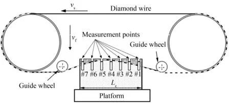
Fig. 2 Illustration of the measurement setup
Three kinds of natural granites, with various grain sizes, were selected for the experiments. Thin sections were prepared from each granite sample. Petrographic studies were conducted using a Leitz Wetzlar polarizing microscope, including the determination of the modal composition and the grain sizes of the studied granites. These examinations are depicted in Fig. 3.The sample granites mainly consisted of quartz, plagioclase, K-feldspar, biotite, and pyroxene. Quartz, feldspar, and biotite were considered the main minerals in the granite composition.
Table 1 summarizes their compositions and mechanical properties and lists the ranges of the mineral grain sizes of the three investigated granites. The test specimens were rectangular, 600 mm long, 200 mm wide and 200 mm thick. The wire speed and the feed rate remained constant at 25 m/s and 8 mm/min, respectively. Water coolant was applied at a constant flow rate of 6 L/min.
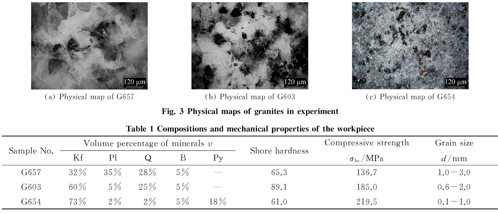
(a)PhysicalmapofG657(b)PhysicalmapofG603(c)PhysicalmapofG654Fig.3PhysicalmapsofgranitesinexperimentTable1CompositionsandmechanicalpropertiesoftheworkpieceSampleNo.VolumepercentageofmineralsvKfPlQBPyShorehardnessCompressivestrengthσbc/MPaGrainsized/mmG65732%35%28%5%—65.3136.71.0-3.0G60360%5%25%5%—89.1185.00.6-2.0G65473%2%2%5%18%61.0219.50.1-1.0
Kf: K-feldspar; Pl: plagioclase; Q: quartz; B: biotite; Py: Pyroxenes.
1.1 Swarf collection
To collect the swarf in the sawing zone, granite chips in the steady sawing state were guided into sample containers through a sloped groove that was cut into the granite, as shown in Fig. 4. This slope groove was 10 mm wide. Slope grooves were cut in different areas along the sawing zone according to the experimental process, such that all swarf along the long sawing arc could be obtained. To limit the influence of slope grooves on the collected chips, the chips were transferred from the final location of the workpiece to its starting point. First, groove #1 was cut near the final workpiece location, and a chip was collected from this groove in the long sawing zone. Groove #2 was then cut and a chip obtained from this groove, and so on. The first groove was 25 mm away from the starting location. The distance between two grooves was fixed at 100 mm. To stabilize the state of the cutting process, the total sawing depth was 15 mm in each sawing experiment.

Fig. 4 Illustration of the sampling grooves distribution
1.2 Observation of swarf morphology
The swarf was sieved into various sizes through a series of mesh screens. The micro-morphologies of the chips were examined using a scanning electron microscope (SEM PHENOM). The chips were cleaned with acetone prior to examination. The mineral components of the swarf were also identified using the optical microscope system Hirox-KH8700.
1.3 PSD analysis
Chip PSD was measured with a laser diffraction particle size analyzer LS13-320. The collected chips were kept in a sampling container for 24 h until the sedimentation process was completed. The deposited chip of 0.25 g was diluted to 2 g/L with distilled water. The refractive index of this water was 1.33. However, the accurate refractive index of granite was difficult to determine given its complex mineral composition. Quartz and plagioclase are the minerals that mainly comprise the three investigated granites, as shown in Table 1. Therefore, the refractive index of granite was set at 1.6 because the refractive indices of quartz and plagioclase were 1.644 and 1.525, respectively. Sodium hexametaphosphate was used as a dispersant to scatter particles uniformly in the solution. The particle solution was subject to ultrasound at 100 W power for 120 s during chip size analysis. The statistical duration of particle size analysis was 90 s.
2 Experiment results
2.1 PSD of the granite swarf
Fig. 5 depicts the PSDs of three granites measured at location #7. Most chips are approximately 10 μm to 200 μm. However, granite chips in the experiment were occasionally larger at 300 μm to 600 μm, as indicated in Fig. 5b.
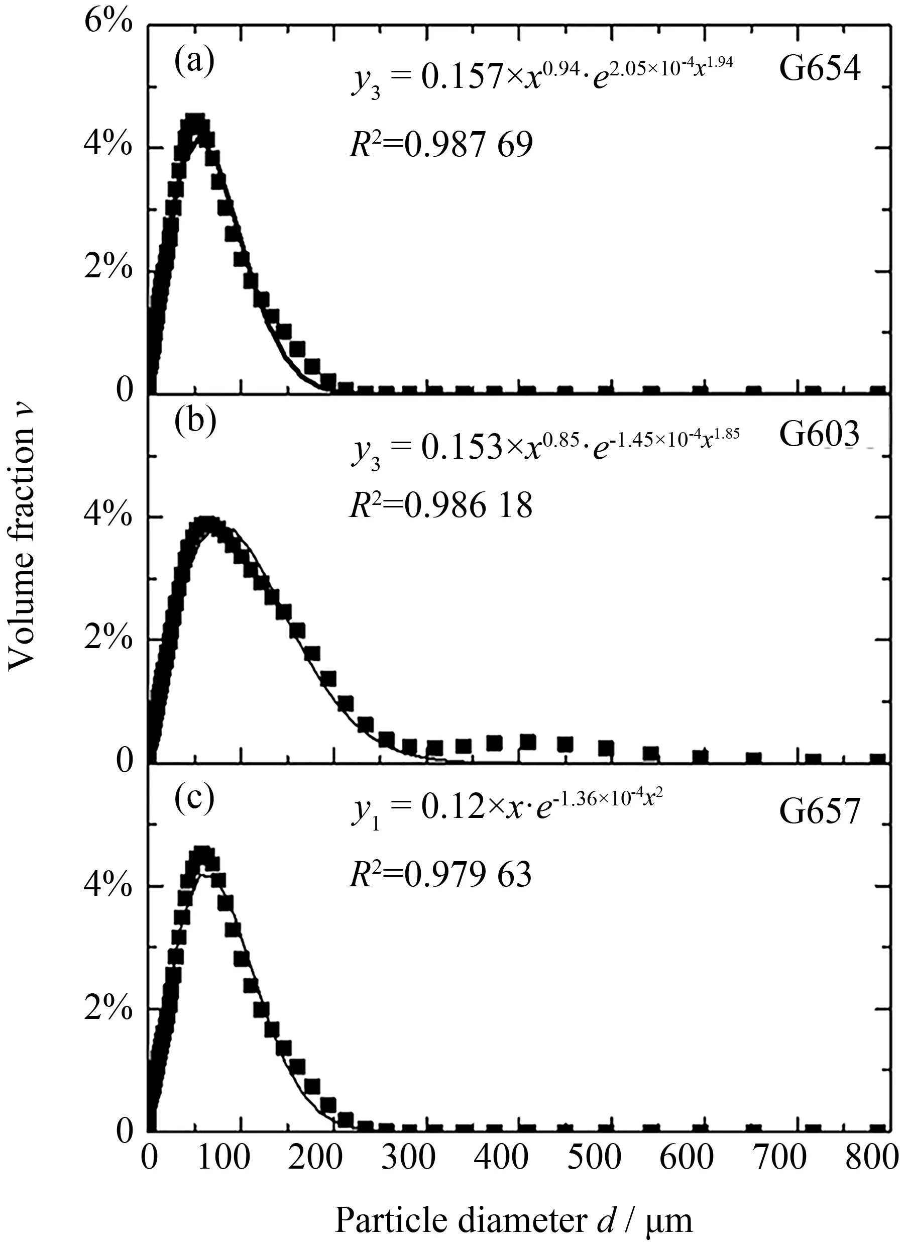
Fig. 5 Granite swarf particle size distribution with lognormal distribution (measurement location #7)
The PSD is unimodal, as displayed in Fig. 5. Thus, it can be described by a mathematical distribution function to analyze the granite swarf quantitatively. The Weibull distribution effectively represents PSDs generated by grinding, milling, and crushing[8-9]. It is still widely used to define PSDs in comminution. Therefore, the Weibull distribution was used to evaluate the sawn chips quantitatively after preliminary analysis. It accorded well with the PSD result of the sawn chip indicated in Fig. 5.
The probability density function of a Weibull random variable is written as
(1)
wherek(>0) is the shape parameter and(>0) is the scale parameter of the distribution. The mean (E) of a random Weibull variable can be expressed as
(2)
whereΓis the gamma function.
The probability density function is fitted for each experimental result and presented in Fig. 5. The mean value of the sawn chips was calculated using Eq. 2. Fig. 6 plots the mean size of the chips broken in different areas of the three granites, which ranged from approximately 40 μm to 80 μm. The mean value of the G603 chips, which were the largest of the three granites, varied between 68 μm and 77 μm. The mean value of the G657 chips ranged only from 45 μm to 65 μm, whereas that of the G654 chips was the lowest at only roughly 40 μm to 54 μm. The mean sizes of the sawn chips varied in the three granites; nonetheless, the sizes of the broken chips decreased slightly along the sawing zone in all experimental granites, as depicted in Fig. 6.
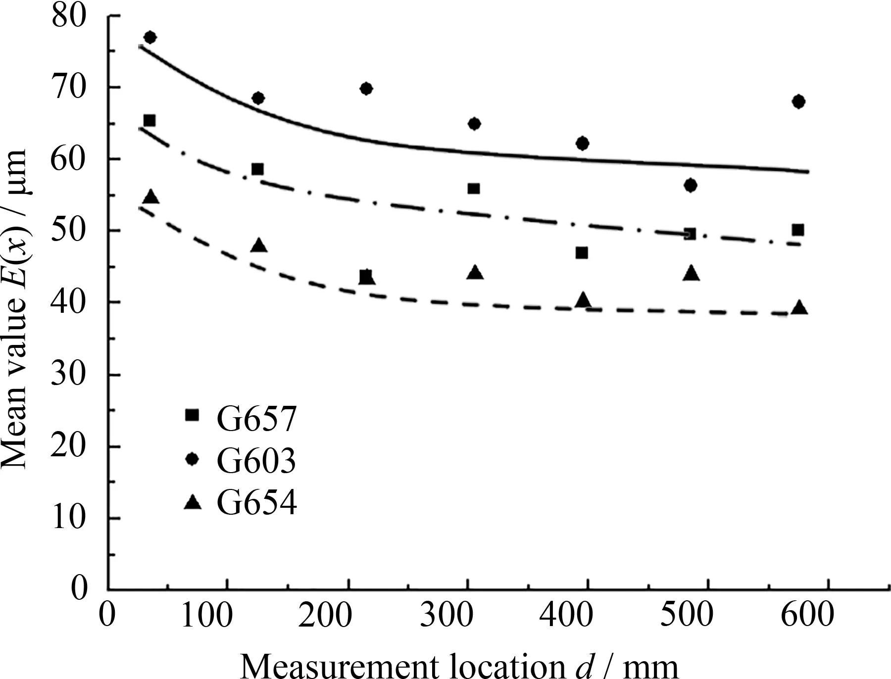
Fig. 6 PSD for 3 granites at different measurement locations
2.2 Morphology examinations
Fig. 7 shows the typical optical micrographs of the swarf with different PSDs. The colors of the sawn chips varied significantly in terms of their primary colors, which are black, white, brown, and clear. Multicolored granite chips could not be identified in all three examined granites, with the exception of large chips, as indicated in Fig. 7a. The different colors indicate various mineral compositions and suggest that the swarf produced by wire sawing is composed of broken pieces of the minerals that constitute the granite. All minerals (quartz, feldspar, and mica) are represented over the entire range, from very fine to coarse particles. The three major minerals are magnified in Fig. 8.

(a)d>212μm(b)180μm Fig. 9 exhibits the morphology of a chip with different mineral compositions as observed through SEM. Unlike the long, thin, and extruded filament-grinding chips of low-melting and soft ductile materials (mid steel, for example)[10], granite generates blocky fracture particles. Fig. 9a displays the conchoidal fracture feature, which is the typical fracture morphology in quartz. Mineral cleavage is incomplete in un-fractured quartz due to external forces originating from a certain direction. Fractures or ruptures shape the quartz into smooth oval surfaces with a concentric pattern and similar shells. Fig. 9b presents the feature of cleavage terrace on feldspar. Feldspar has either a triclinic or a monoclinic crystal system and two or three cleavage surfaces. Fig. 9c shows the biotite, which is typical mica. This mica is monoclinic and has near-perfect basal cleavage as its most prominent characteristic. Its cleavage surface and fracture profile are indicated in Fig. 9c as well. (a)Quartz(b)Feldspar(c)BiotiteFig.8Morphologyofmajorswarf (a)Quartz(b)Feldspar(c)BiotiteFig.9SEMsofswarfwithdifferentmineralcompositions During wire sawing experiments some large stone fragments, that measured approximately 400 μm, were collected. This fragment size is similar to the size of mineral grains that comprise granite. The morphology of these large fragments is illustrated in Fig.7a, which are induced by the agglomeration of chip powder. This finding indicates that the sizes of sawn chips are much smaller than those of the mineral grains that constitute the stone. The stone is broken into particles during wire sawing under the action of the diamond grains. In previous studies, the features of granite fracture are dominated by the transgranular-intergranular fracture[11]. This fracture type is described by the increments in distance within the mineral grains and along the grain boundaries. The chip with an intergranular fracture is similar in size to the original size of the mineral grain. This chip is larger than that with a transgranular fracture. In this experiment, the sawn chips are much smaller in size than the grains of the individual minerals that comprise the granite. This result suggests that the intergranular fracture is dominant in granite-wire sawing and that the binding forces among individual minerals must be greater than those within the minerals. Therefore, these minerals are never dislodged from their matrix as whole grains; rather, they are broken into fragments during wire sawing. This result is consistent with that of studies on the circular sawing of stone[12]. During wire sawing the sawn chip size ranges from approximately 10 μm to 200 μm. These values are much higher than those obtained during the circular sawing[12-13]and wheel grinding[10]of stone. However, morphology examination indicates that rock particles composed of several minerals cannot be identified, which is consistent with previous findings related to the circular sawing of stone[12-13]. This chip morphology also suggests that chip formation is constant across different machining methods. The fracture particles of wire sawing are larger than those for circular sawing and grinding, potentially, because of the flexible cutting mode and the limited stress concentration during wire sawing. The mean size of the sawn chips varies across the three studied granites, as in Fig. 6, despite their similar PSDs. In this work, G657 originally boasts the largest grain among the three granites; whereas G603 has the largest mean chip size. The original grain size of G654 is the smallest among the three granites, as is the size of its sawn chips. This finding indicates that the original size of mineral grains is a factor that affects the size of sawn chips. Moreover, mineral composition and flaw density influence chip formation significantly. Cleavage planes were observed in the SEM morphologies of the major mineral compositions, as indicated in Fig. 9. They facilitate the dislodgement of mineral fragments and are ideal initiation points for cutting. Minerals are typically broken into fragments before intact dislodging along the grain boundaries[12]. The highly incomplete cleavage in quartz broke the mineral into chips that were smaller than those of other minerals, although it corresponded to the mineral hardness in all mineral compositions. Therefore, the increased volume percentage of quartz may suggest that the mean chip size of G657 is smaller than that of G603. The broken chips must be accommodated over the length of the cutting arc prior to release. The cutting arc in wire sawing is longer than that of circular sawing and grinding and can enhance the movements among the swarf, tool and workpiece. Reference [14] points out that diamond wear is mainly caused by grain fractures and friction-induced wear. Moreover, the coolant and the swarf (chips) are combined to produce abrasive slurry that erodes the segment matrix. This erosion initiates a secondary fracture in the chip in combination with the friction against diamond grain, especially given the increased cutting arc. Thus, chip size decreases along the sawing zone (Fig. 6). The movement among the swarf, tool and workpiece is influenced by the following three items: workpiece chemistry and scratch resistance, the mean thickness of undeformed chips, and chip accommodation space[10]. The mean thickness of undeformed chips should be replaced with mean chip size in granite cutting because of the brittle removal method. Small particles are easier to accommodate than large particles, at the same volume, and large chips may induce chip storage problems in wire sawing. The wear of the diamond tool in circular sawing is less than that observed during wire sawing because fine particles are easily accommodated in the space between the bond and work surfaces over the wheel-work contact arc. Most chip sizes range from approximately 10 μm to 200 μm, during wire sawing. This range is smaller than that of the mineral grains that comprise the granite. A morphology examination of the sawn swarf indicates that granite chips composed of several minerals are difficult to identify. Moreover, wire sawing is dominated by an intergranular fracture. In addition, the PSD of the sawn chip conforms to the Weibull distribution. Mean swarf size decreased slightly along the sawing zone in all experimental granites and varied significantly with change of granite. Finally, the sawn chip initiated a secondary fracture in the long cutting arc. HaiRong Wu, H. Guo, R. Y. Zhao and H. Huang would like to acknowledge the financial support from the Science and Technology Projects of Fujian Province (2017H6014), the Science and Technology Project of Education Department, Fujian Province (JA13019), and the Science and Technology Project of Huaqiao University (11QZR09). [1] WRIGHT D N, ENGELS J A. The environmental and cost benefits of using diamond wire for quarrying and processing of natural stone [J]. Industrial Diamond Review, 2003, 63(4): 16-24. [2] KREMSHOFER S, SEEBACHER H. Developments in diamond wire cutting for granite quarries [C]. 1st International Conference on Stone and Concrete Machining, Hannover, Germany, 2011: 33-38. [3] BUTLER-SMITH P W, GRYZAGORIDIS J, DAVIS P R. A single bead test for assessing diamond wire performance [J]. Industrial Diamond Review, 1999, 59: 93-101. [4] OZCELIK Y, BAYRAM F. Optical investigations of bead wear in diamond wire cutting [J]. Industrial Diamond Review, 2004, 64(3): 60-65. [5] JAIN S C, RATHORE S S. Prediction of cutting performance of diamond wire saw machine in quarrying of marble: a neural network approach [J]. Rock Mechanics and Rock Engineering, 2011, 44(3): 367-371. [6] ROBLEDA A S, VILAN A V, LAGO J A L, et al. The rock processing sector: part i: cutting technology tools, a new diamond segment band saw part ii: study of cutting forces [J]. Dyna, 2010, 11(161): 77-87. [7] HHUANG H, HUANG G, XU X P, et al. An experimental study of machining characteristics and tool wear in the diamond wire sawing of granite [J]. Proceedings of the Institution of Mechanical Engineers, Part B: Journal of Engineering Manufacture, 2013, 227(7): 943-953. [8] MATSUO Y, OGASAWARA T, KIMURA S. Statistical analysis of the effect of surface grinding on the strength of alumina using Weibull's multi-modal function [J]. Journal of Materials Science, 1987, 22(4): 1482-1488. [9] SPERO C, HARGREVES D J, KIRKCALDIE R K, et al. Review of test methods for abrasive wear in ore grinding [J]. Wear, 1991, 146(2): 389-408. [10]PAI D M, RATTERMAN E, SHA M C. Grinding swarf [J]. Wear, 1989, 131(2): 329-339. [11]WILLARD R J, MCWILLIAMS J R. Effect of loading rate on transgranular-intergranular fracture in charcoal gray granite [J]. International Journal of Rock Mechanics and Mining Sciences & Geomechanics Abstracts, 1969, 6(4): 415-421. [12]HAUSBERGER P. Stone machinability [J]. Industrial Diamond Review, 1990, 50: 258-261. [13]YILMAZ N G, GOKTAN R M, KIBICI Y. An investigation of the petrographic and physico-mechanical properties of true granites influencing diamond tool wear performance, and development of a new wear index [J]. Wear, 2011, 271(5-6): 960-969. [14]XU X P, LI Y. The effects of swarf in the diamond sawing of granite [J]. Key Engineering Materials, 2003, 250(16): 187-193.

3 Discussion
4 Conclusions
Acknowledgement

