Coupled boundary element methodand fi nite element methodfor hydroelasticanalysisoffl oatingplate
A.I. Shirkol , T. Nasar
Department of Applied Mechanics and Hydraulics, National Institute of Technology Karnataka, Surathkal, Karnataka, India
1.Introduction
The thought of very large fl oating structures (VLFSs) may provide many potential ocean applications, such as fl oating airports, fl oating ice lands, bridges and container terminal. In the design of VLFS, hydroelastic effects play a vital role, i.e.to predict the de fl ection of VLFS hydro-elastic analysis must be carried out very accurately [1–16] . The review papers by Kashiwagi [17] , Squire [18] and Watanabe et al. [1] summary the research on VLFSs modeling of the sea ice fl ow. The study on VLFSs has been analyzed as a fl oating elastic beam by applying Euler Bernoulli’s beam theory or plate structure by using both as thick and thin plates. Mindlin’s theory and classical thin plate theory have been adopted for the analysis of thick and thin plate, respectively. Wave scattering by a horizontal circular cylinder is studied by [33] . The hydroelastic analysis of fl oating structure with hinge connection or inter connected fl oating structure with hinge has been studied by [12–18] and [19,20] .
To analyze the hydro-elastic analysis of fl oating elastic plate, two equations are required which relates velocity potential acting below the plate surface and the displacement of the plate, we refer these two equations as plate and water wave equations, Wang and Meylan [21] , respectively. The modal expansion method and the direct coupling methods used to solve these equations. In the modal expansion method, the plate modes are expanded as sum of the modal functions as described by Kashiwagi [2] or the modes of vibration of free plate by Meylan et al. [22,23] . Evaluation of the dry natural oscillation mode for hinged two-module fl exible structure and evaluation of the hydrodynamic coef fi cients for each mode are calculated in [32] . The equations are solved directly without any expansion of plate modes in the direct method which is shown by [24–27] . Using the modal expansion method, the de fl ection modes of hinge connection are explored by various authors [12–14,19,20] . In general, the modal expansion method is used for simple geometry and for complicated geometry direct method has been used for interconnected and fl exible line connections [13,14] . Among the available literature, it is agreed that the plate equation i.e. equation of motion of the plate is solved by FEM, whereas, equation of water wave is solved by using BEM technique. For this reason many researchers developed a hybrid FEM–BEM technique[12–14,28] . It has seen that the motions of the disk without the barrier are smaller than those of the disk with the barrier [30] . Non-linear shallow water wave equation is used to develop the over wash of the wave on thin plate is studied by [31] . However, they have used different modal function between FEM and BEM, the order of BEM was lower than that of FEM. In order to overcome this drawback, higher order BEM has been used especially for short wavelengths by Wang and Meylan [21] .
In the present study, the direct method has been employed for the hydro-elastic analyses of fl oating elastic plate as adopted by various researchers [4–7] . The FEM is used to discrete the fl oating plate whereas BEM is used to discretize the surrounding fl uid. A BEM–FEM theory is developed such that the number of nodes is same as basis function. The higher order BEM–FEM explored by Kashiwagi [2] and Wang and Meylan [21] uses different basis function for the plate and velocity potential. Herein the proposed model is capable of analyzing any geometry (Cartesian coordinate system) except circular in which polar co-ordinate system must be followed.We present the results for rectangular plate geometry by using the modi fi ed Green’s function which differs from the formulation of [21,28] . The effect of structural properties on the de fl ection of plate behavior is highlighted. The results are compared with the available literature. The error calculation of the model is calculated based upon number of points and panels used to integrate the bounding integral equation.The displacement, convergence and the time for simulation for rectangular geometry have been discussed in the present work.
2.Mathematical formulation
The equation of motion for elastic fl oating plate and linear water wave equations are derived. These describe the motion of the elastic fl oating plate with shallow draft when it is encountered by linear wave motion.
Fig. 1 shows the schematic diagram of the fl oating elastic plate having rectangular shape with Cartesian co-ordinate system. The vertical coordinate,zpoints upward with the water surface at zero and sea fl oor atz= 0. The horizontal co-ordinates arexandy, and are denoted by vectorX.With negligible draft we consider that the plate fl oats freely on the surface of the water with wave encountering at different angles. The variation in bathymetry is also taken into consideration.

Fig. 1. A schematic diagram showing the coordinates used in the solutions and the equations of motion in the water.
2.1. Equation of motion for elastic plate
In order to develop the numerical model with ease, certain assumptions have been made such as, the plate is assumed to be thin, elastic, to fl oat on the water surface with zero-draft,and to be of arbitrary shape. Initially we consider the shape of the plate as rectangular for the convenience of analysis.The equation of motion for the plate is given by the elastic plate equation as given below.

with boundary conditions

whereW(x,yandz) is the plate displacement,Dis the fl exural rigidity of the plate,ρi,handυare density, thickness and Poisson’s ratio of the plate, respectively. Pressure at the water surface acting on the plate is denoted byPandnandsdenote the normal and tangential directions respectively. By using the linearized Bernoulli’s equation we can derive the pressure at the water surface.

φ(x,y,z,λ) is the velocity potential of water,ρis the density of the water, andgis the gravitational acceleration constant.
Equating Eqs. (1) and (3) , we get

By non-dimensionalizing the variables,

Now, adopting the above mentioned dimensionless variables in Eq. (4) .

where the constants are given by

In the foregoing/following section, the derivation of equation of motion for wave and plate interaction is discussed.
2.1.1.Equationofmotionforfl uid–structureinteraction
Considering the single frequency for the solution to represent the displacement and potential as the real parts of complex functions in which time dependence ise-iωt, whereωis the frequency.

Substituting the above real solution in Eq. (5) we get,

Eq. (6) is referred as the equation of motion for the plate.
Consider water of in fi nite depth or fi nite depthH. The potential satis fi es Laplace’s equation with boundary conditions.

SBis the water surface which is covered by plate. As|X| →S∞the velocity potential is subjected to Sommerfeld radiation condition.

φinis incident potential. An assumption is made that the incident potential is a plane wave and is given by,


Eq. (7a –d) can be solved by combining with Eq. (8) and transferring it into an integral equation using free surface Green’s function.
The free-surface Green functionG(X;ξ) satisfy.

whereAandkwave amplitude and wave number with value of2π/λ, respectively. The dispersion equation is given by.
whereξ= (ξ,η). This gives us

According to Wang and Meylan [21] and Kim et al. [5] ,the force surface Green function at in fi nite depth is given by,

The forcing function of fi nite water depth is given by Yiew et al. [30] as follows.

The modi fi ed simple equation which differs from Meylan[23] and Yiew et al. [30] is given below and has been further used in the numerical model.

J0= Bessel function of the fi rst kind of order zero.
K0= Bessel function of the second kind of order zero.
H0(1)= Hankel function of order zero.
H0= Struve function of order zero.
By expressing the integral operator in Eq. (11) as
and can be written as

3.Discrete version of the plate and water wave equations
The equation of motion of the plate Eq. (6) and free surface water waves Eq. (15) are discretized using FEM and BEM,respectively. In FEM discretization, each node contains three degrees of freedom, namely displacement (w), rotation degreex(∂w/∂x) and rotation degreey(∂w/∂y). The displacementw(x) is represented as shown below as a vector of functions.

The basis vector is de fi ned by


The vectoris a vector of elements, which is given by

Now, the basis vectorsNdandwdare having dimensions of 1 × 12 and 12 × 1, respectively.
The potential can be expanded in an identical manner to the displacement and can be given as follows,


In a similar mannerφin(X)can be written as

where

3.1. The plate equation
The potential and displacement is represented in the fi nite element basis functions and Eq. (6) is solved for each panel.The considered plate domain is discretized into number of panels. To eliminatew(x) andφ(x) we apply Eqs. (16) and(20) in Eq. (6) which gives
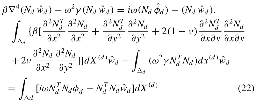
By introducing the following mass matrix [md] as suggested by Meylan [23]

Eq. (22) is the standard form of equation of motion and is given as follows,

3.2. The water wave equations
By introducing the discretized form of potential functions Eqs. (20) and (21) into Eq. (15) , we obtain.


Table 1Parameters used in the model.

Table 2Time and error as the function of panels with wave angle θ= 0.
where

In further, Eq. (27) is simpli fi ed by applying an inner product withNdwhich gives

Again by representing Green’s matrix and introducing mass and stiffness matrix in Eq. (29) we obtain

Eq. (31) represents the water wave equation for a single panel. The solution to Green’s matrix will be discussed in the solution of the Green’s matrix chapter.
4.Solution for the Green’s matrix
The present section deals with the method used to calculate the Green matrix, which is given in Eq. (30) . The principle dif fi culty in the present numerical method is the calculation of the Greens matrix. It is well known that the free surface Green function (12) is singular at |X-ξ| = 0. Hence, the calculation of [g]dewill be separated into two cases. The singularity only occurs whend=e, since in paneld,xlies and in panele,ξlies. There is a need of separation of Eq. (30) i.e. integral form into singular and non-singular cases.
By using an elementary numerical integration method and by approximating the integral form as shown in Eq. (32) below,

where,ξj,νjare the set ofMintegration points and their corresponding weights overSd. By choosing different points and weights, the integral equation given in (30) can be given in discrete form as follows,

whereXi,uiare sets ofNintegration points and their corresponding weights overSd. Combining Eqs. (32) and (33) ,numerical solution for Green matrix [g]deis obtained

wherexi∈Δe,ξj∈ΔeandG(ij)=G(Xi;ξj).
The singularity occurs whenXicoincides withξjand hence, to avoid this condition Eq. (34) is solved by using a set of distinct points (xi) and (ξj). For the case ofd=eit is necessary to use more integration points because of singularity.There are many methods available to calculate the singularity integral, however, coordinate transformation method [29] is widely used among researchers. The same set of integration points forMandNis adopted and their corresponding weights are employed for the case of non-singular Green function.
Further, Eq. (34) can be written as

whereG1isN×Mrectangular matrix of the form

G2isN×Nsquare matrix of the form

N1is 12 ×Nmatrix.

N2isM×12 matrix


Fig. 2. De fl ection of rectangular plate for different number of panels and wave angle of θ= 0: (a) 625, (b) 400, (c) 225 and (d) 100 panels.
5.Solution of the equation of motion for the entire plate
For each panel, discrete versions of plate and water wave equations have been determined and are combined to apply on entire plate. Assembling of global stiffness and mass matrix is done by using a transformation matrix denoted by [o]d.Since we are using a set of uniform panels to discretize the plate, the mass and stiffness matrix are calculated once.

where,

If,qis the total number of nodes in the plate, each transformation matrix [o]dhas 12 ×3qdimensions. By assembling the discrete plate equation Eq. (26) , the entire plate equation is given as,

where the vectorsandare related toandofΔd(FEM panel) by the following relationship,

The coupling of entire water wave Eq. (31) and entire plate equation Eq. (42) is performed by using global Green’s matrix and the fi nal form is given below.

where,

Eq. (45) is solved for elastic motion (w) and velocity potential simultaneously (φ)

The basis functionB(x) is recovered from shape function,while solving the elastic motion or velocity potential.

Table 3Time and error as the function of panels for wave angle θ= 0.

Table 4Time and error as the function of panels for wave angle θ= π/2.

Table 5Time and error as the function of panels for wave angle θ= π/4.

Table 6Time and error as the function of panels for wave angle θ= π/6.
6.Results
The proposed numerical model can be easily applied to calculate the hydroelasticity of the fl oating thin plate at arbitrary depth and for any arbitrary shapes. To verify the proposed numerical model, the simulation time and error in convergence rate is compared with the numerical results of Wang and Meylan [21] . Further, the modeling capacity of the numerical model is demonstrated for rectangular plate in fi nite and in fi nite water depths. The advantage of the present model is that it consists of same number of basis function both in BEM and FEM. Hence, the simulation time of model is expected to be reduced. By increasing the number of integration points (NandM), the accuracy of the model is also expected to be increased. The above said aspects are discussed in the following sections. Table 1 explains the parameter used in the present numerical model as proposed by Wang and Meylan[21] .

Fig. 3. Continued

Table 7Time and error as the function of panels for integration N , M = 2 and wave angle θ= 0.

Table 8Time and error as the function of panels for integration N , M = 2 and wave angle θ= π/2.

Table 9Time and error as the function of panels for integration points N , M = 2 and wave angle θ= π/4.
The time period required to run the model in order to capture the elastic motion/de fl ection pro fi le of the fl oating rectangular plate is recorded. The model is analyzed by increasing the number of panels from 100 to 900 and by considering equal integration points (N=M= 4). The panel dependency of the proposed numerical work is observed to be absent when the panel number crosses 900. Hence, the error is zero when the panel number is 900 and above. Based on this condition,the error is estimated for the considered panel numbers between 100 and 900 at angle of wave attackθ= 0 is shown in Table 2 .

Table 10Time and error as the function of panels for integration points N , M = 2 and wave angle θ= π /6.
Fig. 2 a–e shows elastic motions/de fl ected pro fi les in the plate at fi nite water depth and angle of wave attackθ= 0 by varying number of panels. We observe that as the number of panels in the plate increases the time required for the simulation also increases whereas the error in de fl ection pro fi le will be reduced. It is observed that, as the panel number increases the time required to complete the simulation is also increased.However, the error increases as the panel numbers decreases.
Fig. 3 a–d exhibits the simulation of elastic motions for different angles of wave attack (θ= 0,π/2,π/4 andπ/6) by keeping the integration points (N=M= 4) as constant and panel numbers equals to 900. It can be seen that the elastic motions are captured elegantly over the entire plate as well as at the corners of the plate.
Further, the simulation time for different number of panels is considered and the error in de fl ection of the fl oating elastic plate is presented in Tables 3–6 forθ= 0,π/2,π/4 andπ/6,respectively.
It is learnt that the average error is about 0.40, 0.13, 0.05 and 0.01 for number of panels of 100, 225, 400 and 625 respectively.
Further, the ef fi ciency of the numerical model is studied for integration pointsNandM= 2 and has been compared with integration pointsNandM= 4. Tables 7–10 explain the time required for the simulation and error in the model for the number of panels considered subjected to different angles of wave attack (θ= 0,π/2,π/4 andπ/6). It is observed that the error obtained using integration pointsNandM= 2 is slightly higher than the error obtained using integration pointsNandM= 4. However, the simulation time for integration pointsNandM= 4 is three times higher than the simulation time required for integration points ofNandM= 2.
The average error is observed to be about 0.415 for the angle of wave attacksθ= 0,π/2,π/4 andπ/6. For the wave propagation in line (θ= 0) with the length of the plate, the error is higher than the error observed for the wave propagation in all the direction of wave angles. By considering number of panels as 225, 400 and 625 the error observed for wave propagation inθ=π/4 is less thanθ=π/6.
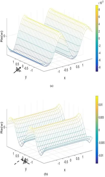
Fig. 4. De fl ection of rectangular plate for different wave angles of attack: (a) θ= 0, (b) θ= π /2, (c) θ= π /4 and (d) θ= π /6.

Fig. 4. Continued
Surface de fl ection of the freely fl oating elastic plate for the integration points ofN,M= 4 andN,M= 2 is shown in Fig. 5 (a) & (b) and Fig. 5 (c) & (d). The de fl ection pro fi le smoothness as the integration points are increased and the error in the model reduced as the number of integration points increases. The de fl ection pro fi les/elastic motions in fl oating plate is projected in Fig. 4 a–d. It is learnt that the smoothness in edges is lesser than the de fl ection pro fi les obtained by integration pointsNandM= 4. Further, it is experienced that the singularity occurs quite often when the integration pointsNandM= 2 than the integration points ofNandM= 4.
The ef fi cacy of the present numerical model at fi nite water depth is explored by comparing with the results of Wang and Meylan [21] . By considering the ( Table 1 ) parameters,the proposed numerical model solves the modi fi ed Green’s function and results are reported here.
Fig. 6 compares the elastic modes/de fl ection in the plate obtained by Wang and Meylan [21] and the present model for different wave attack angles. By examining the de fl ection pro fi les it is understood that the proposed numerical model simulates the edges of the plates smoother than the model by Wang and Meylan [21] due to the usage of modi fi ed Green’s function. Also, it is noticed that a smooth transition of surface mode is captured by the present model which is in accordance with practical sense.
Tables 11–14 provide the comparison of Wang and Meylan[21] and the present numerical model with respect to simulation time and error in simulation for integration points ofN,M= 2. In general, it is observed that the simulation time for the present model is lesser than the simulation time of Wang and Meylan [21] . Further, it is learnt that as the panel increases there is a considerable time saving is observed.
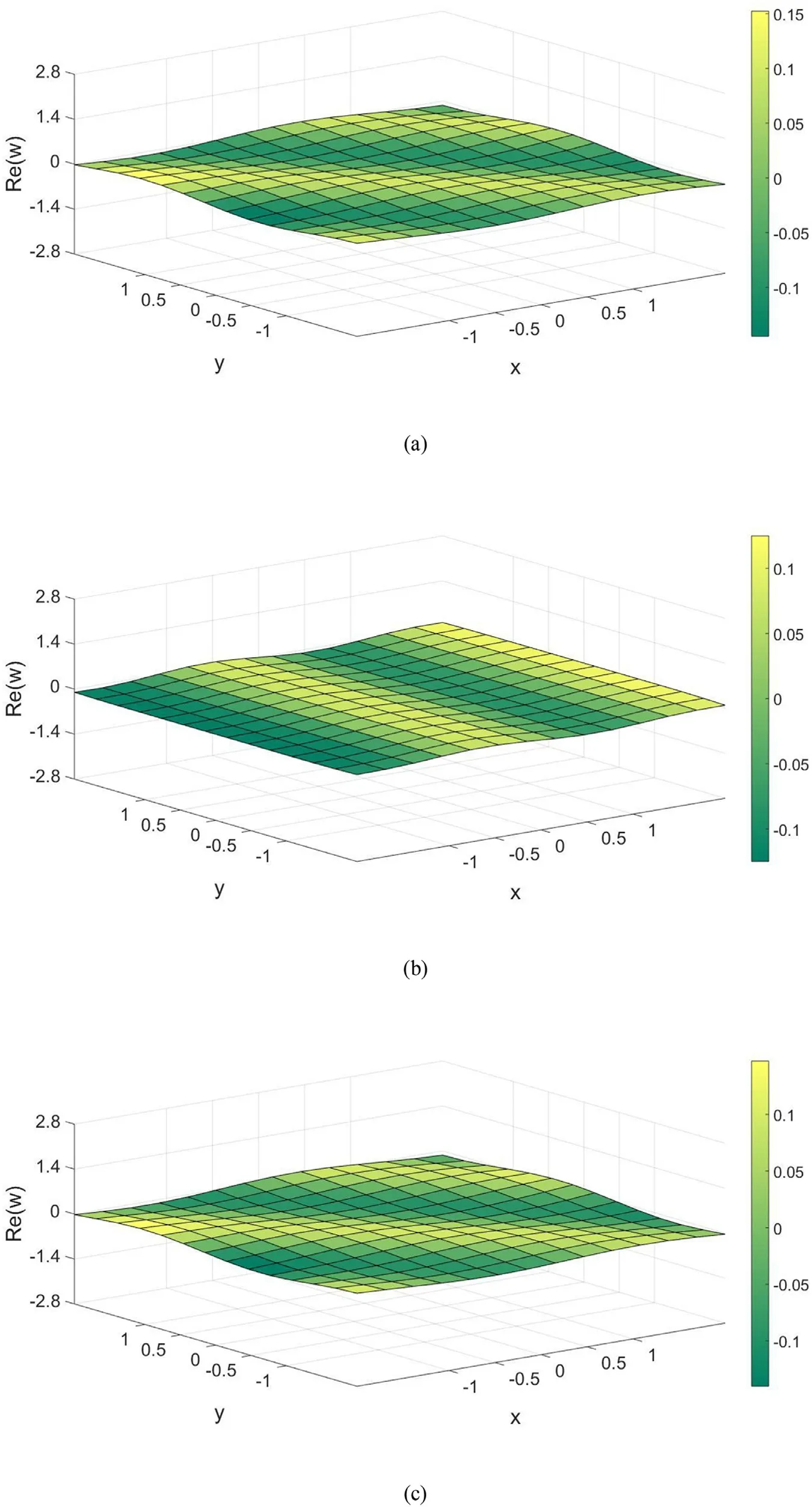
Fig. 5. De fl ection of rectangular plate subjected to angles of wave attack: θ= π/4 and 0 (a) and (b) for N , M = 4, (c) and (d) for N , M = 2.
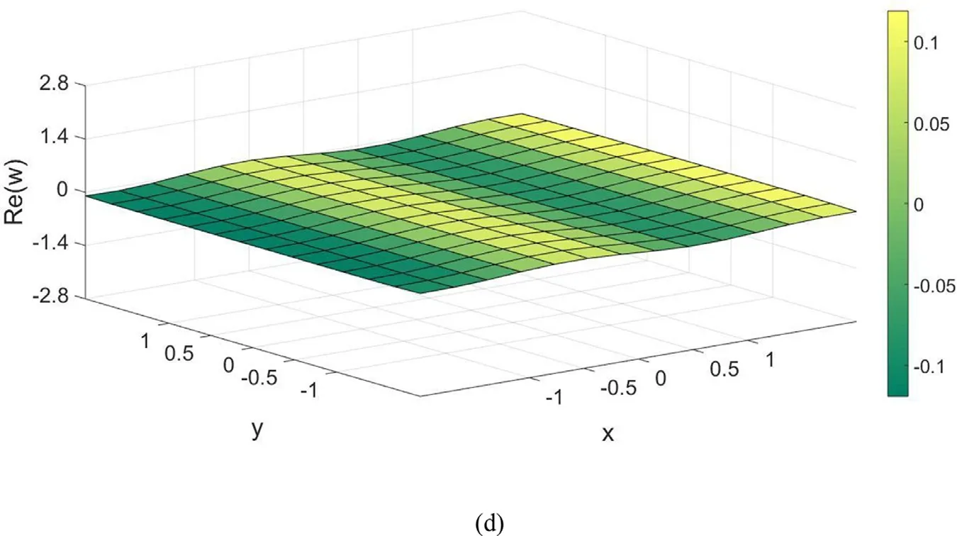
Fig. 5. Continued

Table 11Time and error as the function of panels for integration points N , M = 2 and wave angle θ= 0.
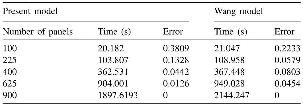
Table 12Time and error as the function of panels for integration points N , M = 2 and wave angle θ= π/2.

Table 13Time and error as the function of panels for integration points N , M = 2 and wave angle θ= π/4.
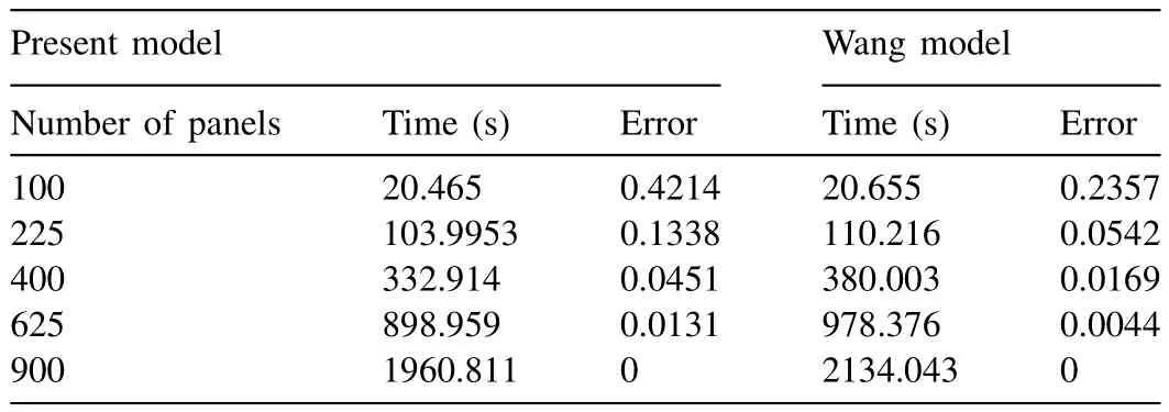
Table 14Time and error as the function of panels for integration points N , M = 2 and wave angle θ= π /6.
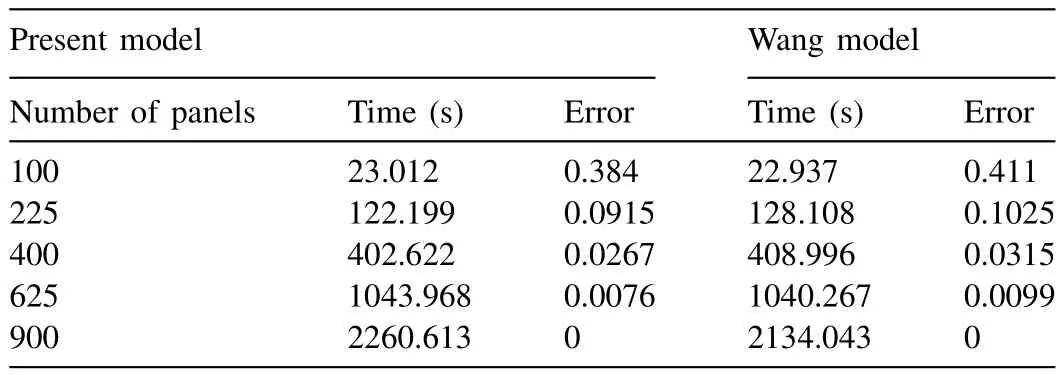
Table 15Time and error as the function of panels for integration points N , M = 4 in in fi nite water depth and wave angle θ= 0.
Fig. 7 captures the de fl ection of the plate at in fi nite water depth from the present model with different wave attack angles forN,M= 4. Also, it compares the surface pro fi le captured by Wang and Meylan [21] . It is noticed that both the models are equally competitive in capturing the surface modes/pro fi les and the de fl ection at the corners of the plate.Tables 15–18 give the comparison in the aspect of time required for simulation and error in the de fl ection of both models. It is understood that the present model gives less error than Wang and Meylan [21] . However, the simulation time is on the higher side for most of the test conditions.
By using 100 panels, the average error is observed to be about 0.374 for different direction of wave propagation considered. For the wave propagation in line (θ= 0) with the length of the plate, the error is higher than the error observed for wave propagation in line (θ=π/2) with the width of the plate by adopting number of panels as 225, 400 and 625 respectively. For the same number of panels, the error observed for wave propagationθ=π/6 is lesser thanθ=π/4.

Fig. 6. De fl ection of rectangular plate for different wave angles of attack: (a) θ= 0, (b) θ= π/2, (c) θ= π/4 (d) θ= π /6 for N , M = 2.

Fig. 7. De fl ection of rectangular plate in in fi nite water depth for different wave angles of attack: (a) θ= 0, (b) θ= π/2, (c) θ= π /4 and (d) θ= π /6 for N ,M= 4.
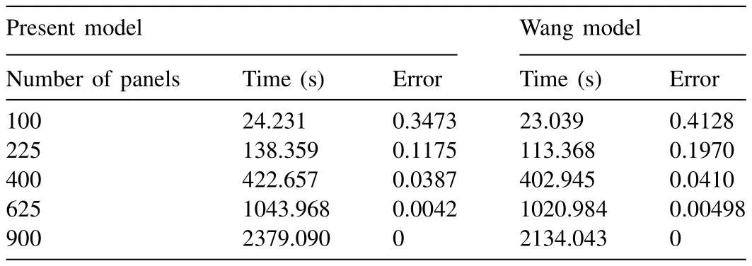
Table 16Time and error as the function of panels for integration N , M = 4 in in fi nite water depth and wave angle θ= π/2.

Table 17Time and error as the function of panels for integration N , M = 4 in in fi nite water depth and wave angle θ= π /4.

Fig. 8. De fl ection of rectangular plate in in fi nite water depth for different wave angles of attack (a) θ= 0, (b) θ= π /2, (c) θ= π /4 (d) θ= π/6 for N = 4 and M = 8.

Fig. 8. Continued
Further, the ef fi cacy of the model has been checked for the higher integration pointsN= 4 andM= 8 at in fi nite water depth. Fig. 8 gives the de fl ection of the fl oating thin elastic plate. A smoother surface pro fi le is observed for all the wave propagation angles considered. The time required for the simulation and error in the model as a function of panels has been studied and are shown in Tables 19–22 .
It is observed that as the integration points increases the time required for the simulation is increased and the error in de fl ection decreases compared withN,M= 4. The model converges as the number of panels reach 400 for integration pointsN= 4 andM= 8, whereas, the model converges at 900 panels forN,M= 2.
By 100 number of panels,θ=π/2 gives less error when compared with other wave directions. A nominal variation in error is observed among different angles of attack for 225 panels. However, error is less for the wave propagation in line (θ=π/2) with the length of the plate. This reduction in error considering different wave angles is due to increase in integration points fromN,M= 2 toN= 4 andM= 8.

Table 18Time and error as the function of panels for integration N , M= 4 in in fi nite water depth and wave angle θ= π/6.

Table 19Time and error as the function of panels for integration N = 4 and M = 8 in in fi nite water depth and θ= 0.

Table 20Time and error as the function of panels for integration N = 4 and M = 8 in in fi nite water depth and wave angle θ= π /2.

Table 21Time and error as the function of panels for integration N = 4 and M = 8 in in fi nite water depth and wave angle θ= π /4.

Table 22Time and error as the function of panels for integration N = 4 and M= 8 in in fi nite water depth and wave angle θ= π /6.
7.Conclusions
The developed model has been analyzed and compared with Wang and Meylan [21] . The present model differs with Wang and Meylan [21] by using modi fi ed Green’s function.The present model uses Bessels and Hankin functions which helps in coupling between plate and water wave equation.The ef fi cacy of the numerical has been checked at fi nite and in fi nite water depth for different parameters such as time required for simulation, error, integration points and number of panels. In fi nite water depth, the model saturates at 900 panels whereas, this value is 400 at in fi nite water depth forN= 4 andM= 8. Further, it is observed that as the integration points and number of panels increase, the time required for simulation is increased. The error tends to decrease when compared with Wang and Meylan [21] . For the case of fi nite water depth,the developed model show good results when compares with Wang and Meylan [21] . The required time for the simulation of the model is on the higher side and the error decreases in a proper interval without any fl uctuations. For the case of infi nite water depth the developed model lags behind the model Wang and Meylan [21] in the simulation time but it shows decent results with respect to error. The proposed model works better than Wang and Meylan [21] at fi nite water depth on the aspect of error in de fl ection. However, the model requires more time than that of Wang and Meylan [21] . As we increase the number of panels, the error reduces gradually in the present model, whereas, the decreasing trend is not observed in Wang and Meylan [21] as it fl uctuates. At in fi nite water depth the developed numerical model lags behind the model developed by Wang and Meylan [21] in terms of time required for the simulation, but provides good agreement with error in de fl ection.
[1] E. Watanabe, T. Utsunomiya, C.M. Wang, Eng. Struct. 26 (2) (2004)245–256, doi: 10.1016/j.engstruct.2003.10.001 .
[2] M. Kashiwagi, J. Mar. Sci. Technol. 3 (1) (1998) 37–49, doi: 10.1007/BF01239805 .
[3] C. Wu, E. Watanabe, T. Utsunomiya, Appl. Ocean Res. 17 (5) (1995)301–310, doi: 10.1016/0141- 1187(95)00023- 2.
[4] J.-G. Kim, et al., Ocean Eng. 78 (2014) 112–123, doi: 10.1016/j.oceaneng.2013.11.006 .
[5] K.-T. Kim, P.-S. Lee, K.C. Park, Int. J. Numer. Methods Eng. 96 (13)(2013) 842–866, doi: 10.1002/nme.4564.
[6] R.E. Taylor, J. Eng. Math. 58 (1) (2007) 267–278, doi: 10.1007/s10665- 006- 9121- 7 .
[7] A.I. Shirkol, T. Nasar, D. Karmakar, Perspect. Sci. 8 (2016) 533–535,doi: 10.1016/j.pisc.2016.06.012.
[8] C.-H. Lee, J.N. Newman, J. Fluids Struct. 14 (7) (2000) 957–970,doi: 10.1006/j fl s.2000.0305 .
[9] J.N. Newman, Mar. Struct. 18 (2) (2005) 169–180, doi: 10.1016/j.marstruc.2005.07.003 .
[10] T.I. Khabakhpasheva, A.A. Korobkin, J. Eng. Math. 44 (1) (2002) 21–40, doi: 10.1023/A:1020592414338 .
[11] C.M. Wang, et al., Appl. Mech. Rev. 63 (3) (2010) 030802, doi: 10.1115/1.4001690.
[12] M. Riyansyah, C.M. Wang, Y.S. Choo, Mar. Struct. 23 (1) (2010) 67–87,doi: 10.1016/j.marstruc.2010.01.001 .
[13] S. Fu, et al., Ocean Eng. 34 (11) (2007) 1516–1531, doi: 10.1016/j.oceaneng.2007.01.003 .
[14] R.P. Gao, et al., Ocean Eng. 38 (17) (2011) 1957–1966, doi: 10.1016/j.oceaneng.2011.09.021 .
[15] B.W. Kim , et al. , The Fifteenth International Offshore and Polar Engineering Conference, International Society of Offshore and Polar Engineers, 2005 .
[16] B.W. Kim, et al., Ocean Eng. 34 (11) (2007) 1668–1679, doi: 10.1016/j.oceaneng.2006.10.018 .
[17] M. Kashiwagi , Int. J. Offshore Polar Eng. 10 (2000) 02doi:ISOPE-00-10-2-081 .
[18] V.A. Squire, et al., Annu. Rev. Fluid Mech. 27 (1) (1995) 115–168,doi: 10.1146/annurev. fl.27.010195.000555 .
[19] E. Loukogeorgaki, D.C. Constantine Michailides, J. Fluids Struct. 31(2012) 103–124, doi: 10.1016/j.j fl uidstructs.2012.02.011 .
[20] D.C. Constantine Michailides, Appl. Ocean Res. 35 (2012) 77–94,doi: 10.1016/j.apor.2011.11.004.
[21] C.D. Wang, M.H. Meylan, J. Fluids Struct. 19 (4) (2004) 557–572,doi: 10.1016/j.j fl uidstructs.2004.02.006 .
[22] M.H. Meylan, V.A. Squire, J. Geophys. Res.: Oceans 101 (C4) (1996)8869–8884, doi: 10.1029/95JC03706 .
[23] M.H Meylan, J. Geophys. Res.: Oceans 107 (C1) (2002), doi: 10.1029/2000JC000713 .
[24] M. Meylan, V.A. Squire, J. Geophys. Res.: Oceans 99 (C1) (1994) 891–900, doi: 10.1029/93JC02695 .
[25] A.J. Hermans, J. Fluids Struct. 14 (7) (2000) 943–956, doi: 10.1006/j fl s.2000.0313 .
[26] K. Yago , H. Endo , VLFS 96 (1996) 209–214 .
[27] Y. Pan, P.K. Sahoo, L. Lu, Ships Offshore Struct. 11 (7) (2016) 774–781, doi: 10.1080/17445302.2015.1066986 .
[28] J.-S. Yoon, et al., Mar. Struct. 36 (2014) 65–87, doi: 10.1016/j.marstruc.2014.02.002.
[29] T. Hamamoto , A. Suzuki , K.I. Fujita , The Seventh International Offshore and Polar Engineering Conference, International Society of Offshore and Polar Engineers, 1997 January .
[30] L.J. Yiew, et al., Ocean Model. 97 (2016) 52–64, doi: 10.1016/j.ocemod.2015.11.008 .
[31] D.M. Skene, et al., J. Fluid Mech. 777 (2015), doi: 10.1017/jfm.2015.378 .
[32] Y. Sun, et al., Int. J. Naval Architect. Ocean Eng. (2017), doi: 10.1016/j.ijnaoe.2017.05.002.
[33] Das, D., J. Ocean Eng. Sci. 1.2 (2016): 135–148.10.1016/j.joes.2016.03.001.
 Journal of Ocean Engineering and Science2018年1期
- Journal of Ocean Engineering and Science的其它文章
- Thenewtypesofwavesolutionsofthe Burger’s equationandthe Benjamin–Bona–Mahonyequation
- Multiple soliton solutionsforthe(3+1)conformable space–time fractional modi fi edKorteweg–de-Vriesequations
- Fuzzyfaulttree analysisofoilandgas leakagein subseaproduction systems
- Onanalyticalsolutionofsystemof nonlinear fractional boundaryvalue problemsassociatedwithobstacle
- RiskassessmentofLNGandFLNGvessels during manoeuvringinopen sea
- Anumerical techniquebasedon collocation methodfor solvingmodi fi ed Kawaharaequation
