
Study on Mechanical Performance and Wear Resistance of Halloysite Nanotubes/PTFE Nanocomposites Prepared by Employing Solution Mixing Method
2018-04-24 06:09ChengZhilinChangXingyuMaLuLiuZanQinDunzhong
中国炼油与石油化工 2018年1期
Cheng Zhilin; Chang Xingyu; Ma Lu; Liu Zan; Qin Dunzhong
(1. School of Chemistry and Chemical Engineering, Yangzhou University, Yangzhou 225002;2. Jiangsu Sinvochem Co., Ltd., Yangzhou, 225002)
1 Introduction
PTFE is a useful self-lubricating material because of its chemical stability, heat resistance, especially the low friction coef ficient. However, the wear rate of pure PTFE is extraordinarily high, which limits its application seriously. To solve the problem effectively, PTFE has been filled with numerous inorganic or natural compounds such as alumina[1-2], glass fiber[3], carbon nanotube[4-6], carbon fiber[7], etc.
Halloysite nanotubes (HNTs) are a type of naturally occurring aluminosilicate (Al2(OH)4Si2O5·nH2O) with a nanotubular structure. Due to the nanotubular shape of HNTs, they possess high aspect ratio and large specific surface area. The range of HNTs in length varies from 0.2 μm to 2 μm. The range in the inner diameter and the outer diameter of the tubes varies from 10 nm to 40 nm and from 40 nm to 70 nm, respectively. As the economically available raw materials, HNTs used as fillers have exhibited many promising applications in polymer due to their inherent hollow nanotube structure and different outside and inside chemistry[8-11]. Compared to carbon nanotubes(CNTs), HNTs also possess the advantages of high stability, resistibility against organic solvents and ease of disposal or reusability. It has been reported that HNTs have been demonstrated to be the ideal reinforcement candidate fillers for fabricating polymeric composites with improved mechanical performance[12-15].
As for HNT filler, there are two urgently addressed factors determining the performance of nanocomposites, viz.:a good dispersion of HNTs in the polymer matrix and a desirable interfacial af finity between HNTs and the polymer[16-18]. The relatively weak tube–tube interactions and other structural features make HNTs readily dispersible in polar solvents via stirring. Wang, et al.[19]reported that the Young’s modulus of the HNTs/PVDF nanocomposites with 20% of HNTs prpared by employing the solution mixing method increased by 1.6 times larger than that of pure PVDF. Ismail, et al.[20]reported that the tensile strength of the HNTs/NR nanocomposites prepared by using the solution mixing method was by about 0.1—1 MPa higher than that prepared by using the drying mixing method. So far, we have not found any information about the study of PTFE nanocomposite filled with HNTs prepared by employing the solution mixing method.
Herein, the mixing method and the dispersed solvent of HNTs-PTFE mixture were investigated. The PTFE nanocomposites filled with different mass fractions of HNTs were prepared by means of the cold compression molding method. The effects of those mixing conditions on the mechanical and friction properties of the nanocomposites were studied. Finally, the antiwear mechanism of the nanocomposites was discussed by analyzing the worn surface and the debris of nanocomposites.
2 Experimental
2.1 Materials and methods
Before using, the pristine HNTs powder (purchased from the Yangzhou Xigema New Material Co., Ltd, China) was initially purified. HNTs powder (with its chemical composition listed in Table 1) was dispersed in deionized water under vigorous stirring to yield a 10% aqueous dispersion. Then, it was heated to 60 °C for 6 h under stirring for improving the dispersion of Hal nanotubes in water,followed by successive washing and centrifugation with deionized water at least three times. Finally, the purified product was dried at 60 °C in the oven, denoted as Hal nanotubes-p.
PTFE (purchased from the Shanghai 3F New Material Co., Ltd.) and HNTs (purchased from the Yangzhou Xigema New Material Co., Ltd.) were mixed mechanically.The HNTs/PTFE nanocomposites were prepared by using the cold compression molding method.
Firstly, a certain proportion of PTFE and HNTs was mixed in ethanol, isopropanol, and acetone, respectively.The mixtures were then subject to volatilization at ambient temperature. Finally, the specimens were prepared by the cold compression molding method under a pressure of 10 MPa and sintered at 375 °C for 2 h. The mass fractionof HNTs and PTFE in different solvents was displayed in Table 2. In addition, the variation of the mass fraction of HNTs in the PTFE nanocomposites was investigated as depicted in Table 3.
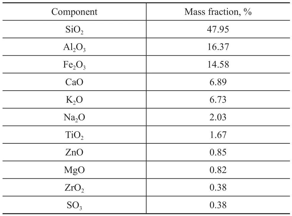
Table 1 The chemical composition of HNTs
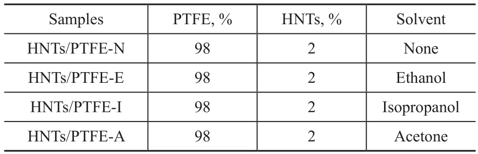
Table 2 HNTs and PTFE mixed in different solvents

Table 3 HNTs/PTFE nanocomposites with different HNTs mass fractions prepared by employing ethanol solvent
2.2 Mechanical testing
The tensile strengh testing was carried out by a WDW-5 machine (made by Shanghai Longhua Co.). The tensile speed was 50 mm/min. The sample size was 42.8×5.9×0.8 mm3. Each specimen was tested for five times to acquire the mean value. The thickness of each specimen was the average of five measurements taken along the gauge length with a digital micrometer. All the data were shown as a mean ± standard deviation. A one-way analysis of variance (ANOVA) was performed to compare the mean values among different groups. Statistical significance was tested at p<0.05.
2.3 Tribological testing
The tribological tests were performed with a MMW-1 friction and wear testing machine (made by the Jinan Chenda Co., Ltd., China). The tribological tests were conducted on a ring-on-ring friction and wear tester. The contact schematic diagram of frictional parts is shown in Figure 1. Each sample was tested for three times to acquire the mean value.
The test parameters and environmental conditions are as follows: Applied load: 200 N; Rotating speed: 200 r/min;Test duration: 60 min; Temperature: 25±2 °C; Relative humidity: 50%±10%.
The friction coef ficient is obtained by the computer automatically. The volume wear rate K (cm3/h) is calculated according to the following equation:
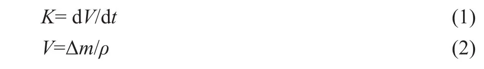
where dV and dt are the volume loss and the sliding time,respectively; Δm is the mass loss in mg and ρ is the density of PTFE composites in g/cm3.
2.4 Characterization
The SEM images were recorded by a Hitachi S-4800 electron microscope operating at an acceleration voltage of 10 kV (Hitachi Limited, Japan). For rendering electric conductivity, the samples were gold-plated before SEM observation. The TMA analysis was recorded by a TMA/SS 6300 thermo-mechanical analyzer (made by Seiko,Japan). The size of spline was prepared to be 10 mm×10 mm×4 mm and the load was 50 N. The measurement was started from the room temperature to 350oC at a temperature increase rate of 2oC/min.
3 Results and Discussion
Figure 2 shows the tensile stress and elongation at break of the HNTs/PTFE nanocomposites prepared by employing different solvents. Compared to pure PTFE, the PTFE nanocomposite with 2% of HNTs obtained through mechanical mixing showed an increment in tensile strength.More importantly, those nanocomposites prepared through mixing with different solvents showed a higher tensile strength than that prepared through mechanical mixing. Among these solvents adopted herewith, the HNTs/PTFE nanocomposite prepared through mixing with ethanol solvent had a larger tensile strength. This suggests that the solution mixing method can make HNTs better dispersed in the PTFE matrix as compared to the mechanical mixing method. By comparing the elongation at break, after filling with HNTs, the elongation at breaks of the HNTs/PTFE nanocomposites decreased obviously. The reason was that the filling of PTFE matrix with HNTs could increase the stiffness of nanocomposites which was responsible for the decrement in elongation at break[21]. However, the nanocomposites prepared by the solution mixing method had a lower elongation at break than that prepared via the mechanical mixing. This result was likely attributed to the higher chain restriction in the solution mixing method[22]. Besides, the elongation values at break decreased as usual when the modulus of the material was improved. The uniform dispersion of filler is important to make the matrix distribute the force onto the fillers which carry most of the applied load and hence is able to withstand the stress. Generally, nanocomposites prepared via the solution mixing method show higher tensile strength than nanocomposites prepared through mechanical mixing.
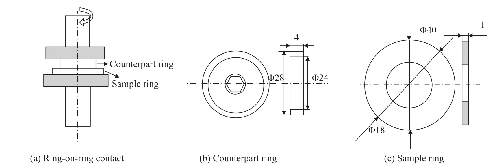
Figure 1 Schematic diagram of wear tester
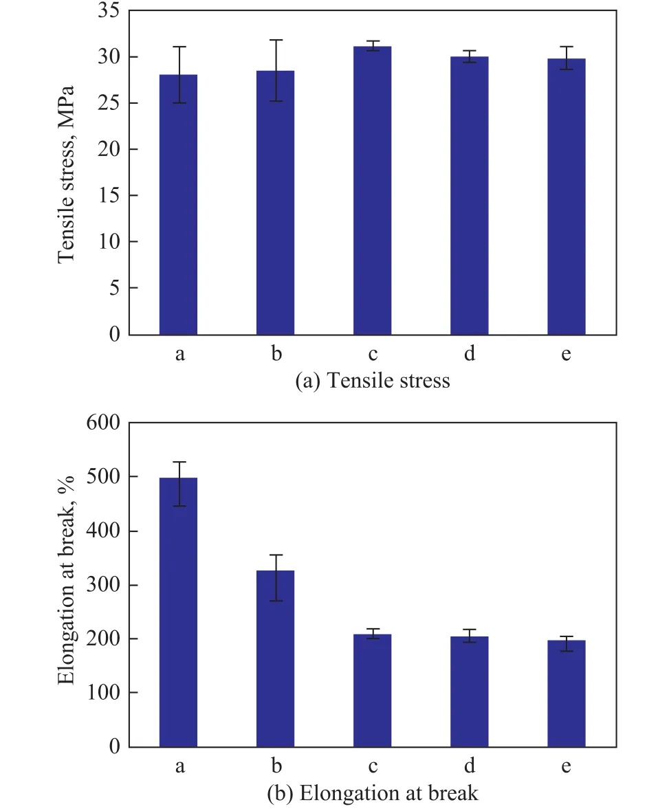
Figure 2 The tensile stress and elongation at break of PTFE nanocomposites
Figure 3 shows the Young’s modulus of pure PTFE and HNTs/PTFE nanocomposites prepared by employing the solution mixing method in different solvents. In contrast to pure PTFE, the Young’s modulus of the HNTs-filled nanocomposite prepared by using the drying mixing method was about 2 times larger than that of pure PTFE,whereas the Young’s modulus of those nanocomposites prepared by employing the solution mixing method was about 3.5 times and 1.3 times larger than that of pure PTFE and the nanocomposites prepared though mechanical mixing. These results revealed that the stiffness of the nanocomposites filled with HNTs was obviously improved[23]. Especially for the nanocomposites prepared by employing the solution mixing method, the effect on the stiffness was extremely obvious.
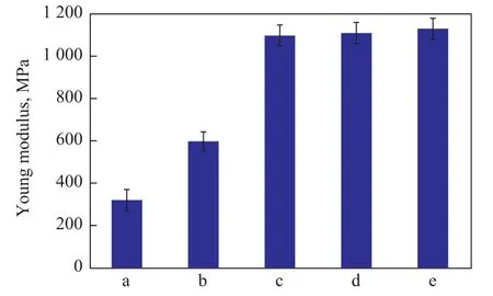
Figure 3 The Young’s modulus of PTFE nanocomposites
The linear expansion coefficient is a crucial index for wear-resistant polymer in practical application. Figure 4 shows the elongation length of pure PTFE and HNTs/PTFE nanocomposites with different HNTs contents prepared by employing the solution mixing method. The average linear expansion coef ficients calculated from the elongation length of the HNTs/PTFE nanocomposites were smaller than that of pure PTFE in the temperature range of 30—200 °C, demonstrating that the HNTs/PTFE nanocomposites possessed the lower expansion performance. At temperatures exceeding 300 °C, the average linear expansion coef ficient of PTFE and the HNTs/PTFE nanocomposites sharply rose, whereas the latter still was lower than the former. The glass transition temperatures(Tg) of the nanocomposites with an increasing HNTs filling content were more obviously elevated than that of pure PTFE. Therefore, the PTFE nanocomposites filled with HNTs featuring good expansion performance and higher Tg were advantageous in the practical application.Figure 5 shows the SEM images of the cross-section of the HNTs/PTFE nanocomposites containing different HNTs mass fractions. The fiber structure of the surface of the cross-section of a PTFE slab shown in Figure 5-a was probably caused by fracture when the PTFE specimen was broken. This structure was not found on the surface of the cross-section of the HNTs/PTFE nanocomposite shown in Figure 5b, c, d, and e. The fracture surface of the HNTs/PTFE nanocomposite with 2% of HNTs indicates to a good dispersion. With the increasing of HNTs content in PTFE matrix, there appeared some HNTs aggregates as shown in white circles in Figure 5-c, d, and e. It is believed that at higher filling of HNTs, the poorer dispersion of HNTs is ascribed to the filler– filler interaction which is stronger than the filler–rubber interaction[24,25]. At lower content of HNTs, since the outer diameter of HNTs with 30 nm–50 nm is of the same order of magnitude as the dimension of PTFE molecule, HNTs are therefore inclinable to intertwinding with PTFE molecules during preparation.Because of their stronger mechanical properties and high-er aspect ratio than those of graphite fibers, HNTs are able to reinforce HNTs/PTFE composites significantly, and are capable of preventing the crystal structure of PTFE from being destroyed during the friction test. This is the reason for the absence of the fiber structure on the surface of the cross-section of the HNTs/PTFE composite. By contrast, crystals of PTFE are drawn out from a PTFE surface by shear during a friction test. HNTs can effectively impede this drawing-out of PTFE crystals, thus improving the wear resistance of HNTs/PTFE composites significantly.
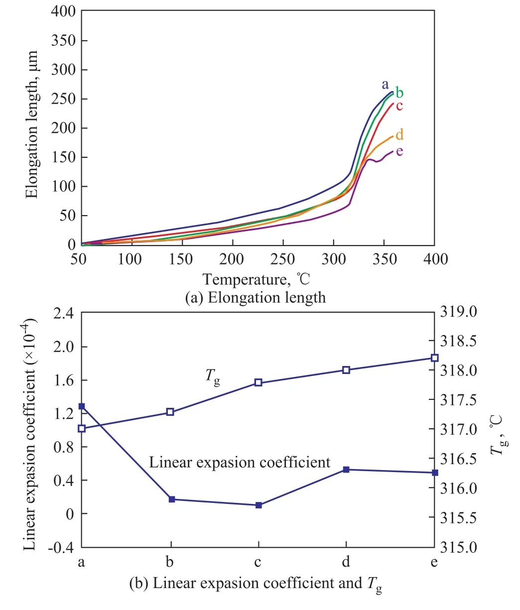
Figure 4 The elongation length of pure PTFE and HNTs/PTFE nanocomposites
Figure 6 shows the friction coefficients depending upon the sliding time for pure PTFE and HNTs/PTFE nanocomposites preared by employing the solution mixing method.The friction coefficient of pure PTFE firstly had a little rise from 0.15 to 0.17, and afterwards declined until it became stabilized after 1500 s. The final friction coef ficient reached ca. 0.14. The friction coefficient of the HNTs/PTFE nanocomposites prepared by employing the dry mixing method indicated the similar tendency with pure PTFE,which ultimately attained 0.13. However, the HNTs/PTFE nanocomposites with 2% of HNTs prepared by employing the solution mixing method in different solvents showed a different tendency. The friction coefficients of the HNTs/PTFE composites prepared by employing the solution mixing method obviously rose after 1 000 s of sliding time and ultimately reached about in the range of 0.20. Figure 7 shows the friction coef ficient of the PTFE/HNTs composites with various HNTs contents prepared by employing the solution mixing method. The further addition of HNTs in the PTFE matrix increased the friction coef ficient of the composites significantly. At the start of sliding, all the composites moving against a #45 carbon steel exhibited a relatively high coef ficient of friction except pure PTFE, followed by a steady-state sliding motion until the coef ficients of friction remained unchanged due to the formation of the steady transfer films on the counterface during the repetitive sliding action. It is well known that the transfer film formed on a counterface during sliding plays an important role in the tribological behavior of polymers. It can be seen that the addition of more HNTs could increase the friction coefficient significantly. It may occur because increasing the percentage of HNTs in the PTFE could increase the hardness and strength of PTFE composites, and would consequently decrease the real contact area of the pair.Figure 8 shows the fraction coef ficients of pure PTFE and the HNTs/PTFE nanocomposites operating under varying applied loads. The friction coef ficients of pure PTFE and the HNTs/PTFE nanocomposites prepared by employing the drying mixing method continuously plunged with an increasing applied load. However, the friction coef ficients of the HNTs/PTFE nanocomposites prepared by adopting the solution mixing method descreased more slowly than those of PTFE prepared by using the drying mixing method. This should be ascribed to the good dispersion of HNTs in the PTFE matrix prepared through the solution mixing approach.
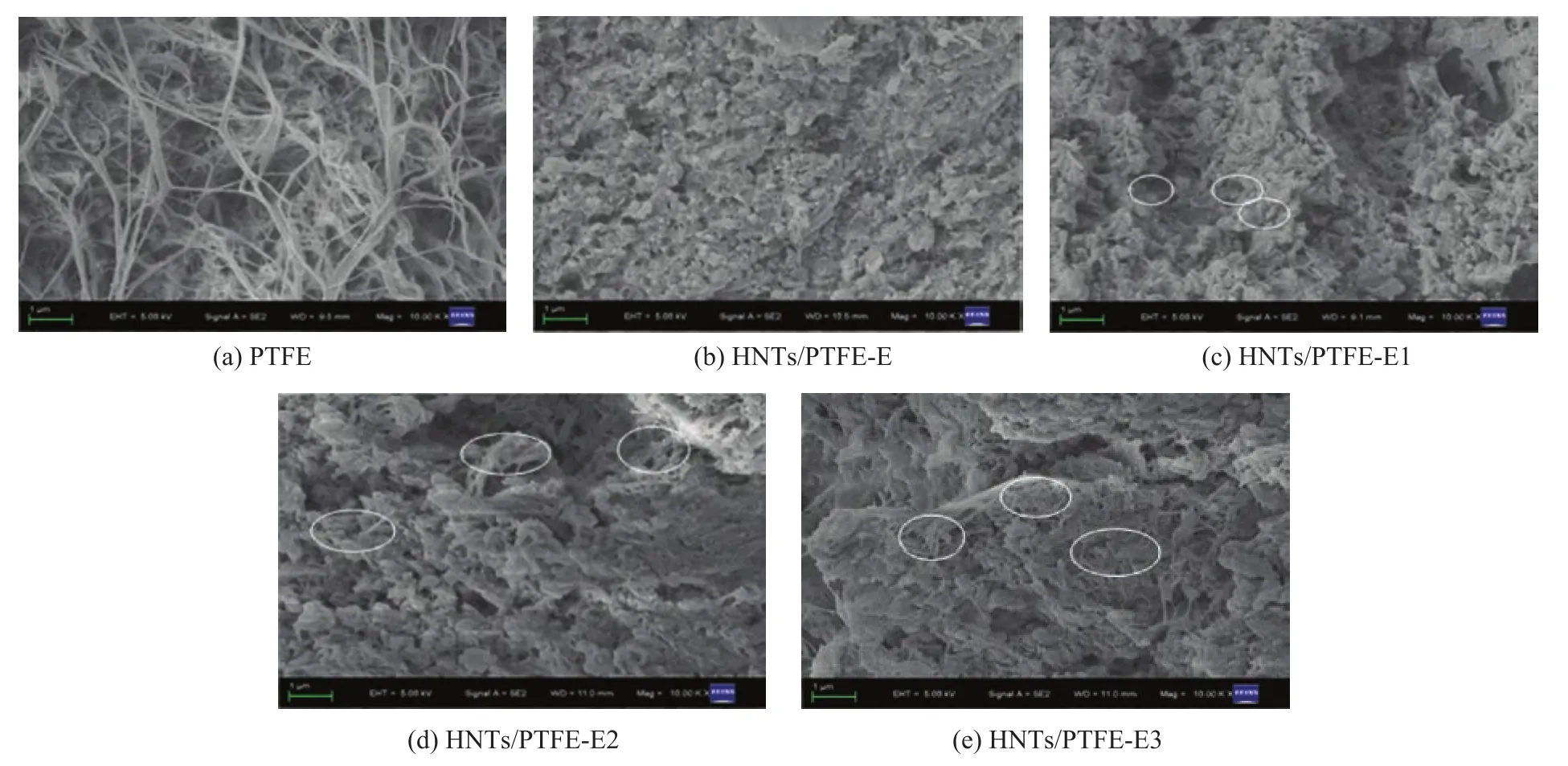
Figure 5 The SEM images of the fracture section of PTFE nanocomposites prepared via the solution mixing method
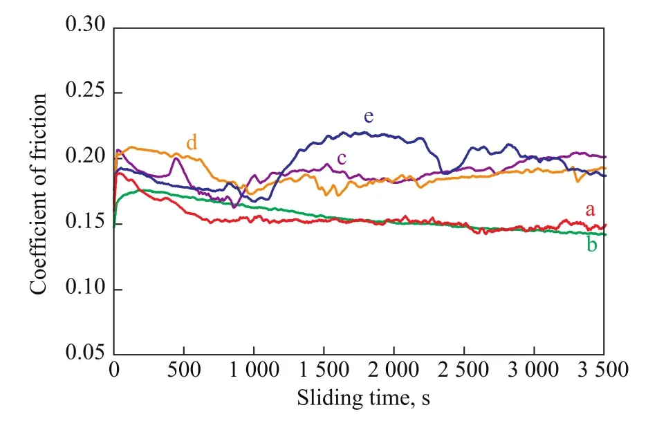
Figure 6 The friction coef ficient of PTFE nanocomposites prepared via the solution mixing method with different solvents (with an applied load of 200N)
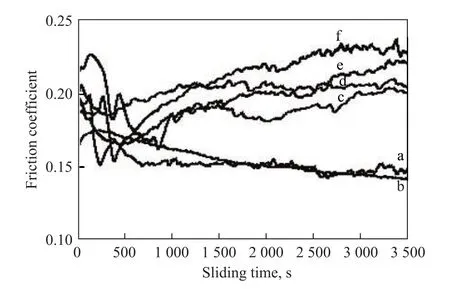
Figure 7 The friction coef ficient of PTFE nanocomposites with different HNTs fractions prepared by using the solution mixing method in ethanol (with an applied load of 200N)
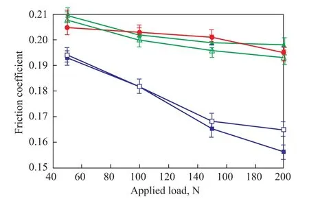
Figure 8 The friction coef ficient of PTFE nanocomposites operating under different applied loads
Figure 9 shows the volume wear rates of pure PTFE and the HNTs/PTFE nanocomposites. The incorporation of HNTs could cause a dramatic improvement in the wear resistance of PTFE. The volume wear rate of pure PTFE was about 0.55 cm3/h, whereas the HNTs/PTFE nanocomposite with 2% of HNTs prepared by employing the drying mixing method showed a 50% decrease in the high wear rate as compared to pure PTFE. Surprisingly, the wear rates of the HNTs/PTFE nanocomposite prepared by employing the solution mixing method were about 5—10 times and 11—20 times less as compared to those of samples prepared by employing the drying mixing method and pure PTFE.The method of solution mixing in ethanol denoted a lowest wear rate among three solvents adopted thereby.
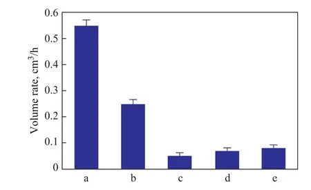
Figure 9 The volume wear rate of pure PTFE and PTFE/HNTs nanocomposites
Figure 10 displays the SEM images of the worn surfaces of pure PTFE and the HNTs/PTFE nanocomposites prepared via the solution mixing method. The microgrooves and banding tears can be clearly observed on the surface of pure PTFE. The reason is that the Van der Waals forces of the PTFE modules are weak. This phenomenon confirms the poor wear behavior of pure PTFE. As regards the sample prepared through dry mixing (Figure 10-b),it can be seen that a large flake-like segment could be found in the worn surface, which was peeled-off from the composite matrix due to the applied load and slider velocity. It is believed that the subsurface damage and the material loss had taken place due to the repeated sliding of the hard counterface asperities on the soft composite surface which was consequently extended, detached and then pulled-out as wear debris[1,26]. In Figure 10-c, d, and e,some exposed HNTs with better dispersion were discovered in the PTFE surface. With the increase of HNTs filling, there were no large flake-like segments on the worn surfaces. This could occur because a large number of HNTs existed in the worn surfaces, which could prevent the forming of the transfer film quickly. Figure 11 represents the SEM images of the wear debris of pure PTFE and the HNTs/PTFE nanocomposites with different HNTs fractions prepared via the solution mixing method. There is some relatively smaller wear debris produced in the HNTs/PTFE nanocomposites in comparison with those in the pure PTFE. With the increase of HNTs fraction, the wear debris in the HNTs/PTFE nanocomposites became smaller. The smaller wear debris had more opportunity to stay longer at the contacting section during the friction process[1,26], thus exhibiting a better wear resistance.
The action of fillers to reduce wear is categorized into three types. They cover the formation of a thick and strongly adhering transfer film, the load supporting action and the prevention of the large-scale destruction of banded structures, and the reduction of wear debris in size[26].In these mechanisms, the formation of a thick and strongly adhering transfer film is commonly accepted. When sliding against the steel counterpart, the load can be transferred to the HNTs, the wear resistance of which is much higher than that of PTFE matrix. The existence of HNTs in the friction interface could decrease the direct contact of PTFE resin with the steel counterpart and slow down the formation of a transfer film. The further addition of HNTs in PTFE could result in the distinct increase of the friction coef ficient, which is attributed to the poor dispersion of HNTs at high filling percentage in PTFE matrix.
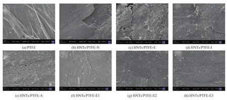
Figure 10 The SEM images of worn surfaces of PTFE composites (x10000)
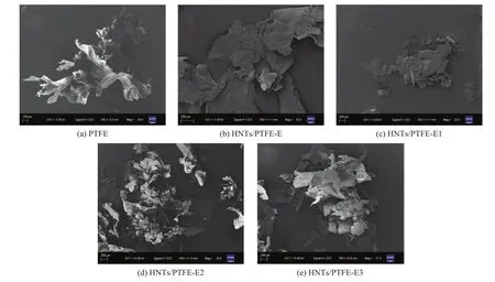
Figure 11 The SEM images of wear debris of pure PTFE and HNTs/PTFE nanocomposites via the solution mixing method in ethanol
4 Conclusions
Using halloysite nanotubes (HNTs) as the reinforcing fillers, the HNTs/PTFE nanocomposites have been prepared by employing the solution mixing method. Upon comparing with the dry mixing method, it can be concluded that the dispersion of HNTs in PTFE matrix was distinctly improved by the solution mixing method. Among different solvents, ethanol serving as the mixing solvent exhibited the best dispersive ability. The mechanical and antiwear performance of the HNTs/PTFE nanocomposites prepared by employing the solution mixing method was significantly improved as compared to those of pure PTFE and samples prepared by using the dry mixing method. The analyses of the worn surfaces and wear debris of these nanocomposites indicated that a proper addition of HNTs in PTFE was conductive to the reduction of wear and improvement of the antiwear ability.
Acknowledgment:This work was supported by the Talent Introduction Fund of Yangzhou University (2012), the Key Research Project-Industry Foresight and General Key Technology of Yangzhou (YZ2015020), the Innovative Talent Program of Green Yang Golden Phoenix (yzlyjfjh2015CX073),the Yangzhou Social Development Project (YZ2016072), the Jiangsu Province Six Talent Peaks Project (2014-XCL-013),and the Jiangsu Industrial-Academic-Research Prospective Joint Project ( BY2016069-02). The authors also acknowledge the Project Funded by the Priority Academic Program Development of Jiangsu Higher Education Institutions. The data of this paper originated from the Test Center of Yangzhou University.
Reference
[1] Krick B, Pitenis A, Harris K L, et al. Ultralow wear fluoropolymer composites: Nanoscale functionality from microscale fillers [J]. Tribology International, 2015, 95:245–255
[2] Ye J, Khare H S, Burris D L. Transfer film evolution and its role in promoting ultra-low wear of a PTFE nanocomposite[J]. Wear, 2013, 297(1/2): 1095–1102
[3] Vohra K, Anand A, Haq M I, et al. Tribological characterization of a self-lubricating PTFE under lubricated conditions [J]. Materials Focus, 2016, 5: 1–4
[4] Makowiec M E, Blanchet T A. Improved wear resistance of nanotube- and other carbon- filled PTFE composites [J].Wear, 2017, 15: 77–85
[5] Vail J R, Burris D L, Sawyer W G. Multifunctionality of single-walled carbon nanotube– polytetrafluoroethylene nanocomposites [J]. Wear, 2009, 267(1/4): 619–624
[6] Sanci M E, Halis S, Kaplan Y. Optimization of machining parameters to minimize surface roughness in the turning of carbon- filled and glass fiber- filled polytetra fluoroethylene[J]. Materials Design and Application, 2017, 65: 295–305
[7] Liu P, Lu R G, Huang T, et al. A study on the mechanical and tribological properties of carbon fabric/PTFE composites [J]. Journal of Macromolecular Science Part B,2012, 51(4)4: 786–797
[8] Liu M, Guo B, Du M, et al. Halloysite nanotubes as a novel β-nucleating agent for isotactic polypropylene [J].Polymer, 2009, 50(13): 3022–3030
[9] Rooj S, Das A, Thakur V, et al. Preparation and properties of natural nanocomposites based on natural rubber and naturally occurring halloysite nanotubes [J]. Materials and Design, 2010, 31(4): 2151–2156
[10] Lvov Y, Abdullayev E. Functional polymer–clay nanotube composites with sustained release of chemical agents [J]. Progress in Polymer Science, 2013, 38(10/11):1690–1719
[11] Pasbakhsh P, Ismail H, Ahmad F M N, et al. EPDM/modified halloysite nanocomposites [J]. Applied Clay Science, 2010, 48(3): 405–413
[12] Ismail H, Pasbakhsh P, Ahmad F M N, et al.Morphological, thermal and tensile properties of halloysite nanotubes filled ethylene propylene diene monomer(EPDM) nanocomposites [J]. Polymer Testing, 2008,27(7): 841–850
[13] Pasbakhsh P, Ismail H, Ahmad F M N, et al. The partial replacement of silica or calcium carbonate by halloysite nanotubes as fillers in ethylene propylene diene monomer composites [J]. Applied Polymer and Science, 2009,113(6): 3910–3919
[14] Liu Z, Qin X X, Qin D Z, et al, Preparation and mechanical properties of PAN/HNTs composite nanofibers[J]. China Petroleum Processing and Petrochemical Technology,2017, 19 (1): 92–98
[15] Jia Z X, Luo Y F, Guo B C, et al. Reinforcing and flameretardant effects of halloysite nanotubes on LLDPE [J].Polymer-Plastics Technology and Engineering, 2009,48(6): 607–613
[16] Handge U A, Hedicke-Höchstötter K, Altstädt V.Composites of polyamide 6 and silicate nanotubes of the mineral halloysite: Influence of molecular weight on thermal, mechanical and rheological properties [J].Polymer, 2010, 51(12): 2690–2699
[17] L. N. Carli, T. S. Daitx, G. V. Soares, J. S. Crespo, R.S. Mauler. The effects of silane coupling agents on the properties of PHBV/halloysite nanocomposites [J]. Applied Clay Science, 2014, 87(4): 311–319
[18] Ye Y P, Chen H B, Wu J S, et al. Evaluation on the thermal and mechanical properties of HNT-toughened epoxy/carbon fibre composites [J]. Composites Part B Engineering, 2011, 42(8): 2145–2150
[19] Wang B, Huang H X. Incorporation of halloysite nanotubes into PVDF matrix: Nucleation of electroactive phase accompany with significant reinforcement and dimensional stability improvement[J]. Composites Part A, Applied Science & Manufacturing, 2014, 66: 16–24
[20] H. Ismail, S. Z. Salleh, Z. Ahmad. Properties of halloysite nanotubes-filled natural rubber prepared using different mixing methods [J]. Materials & Design, 2013, 50(17):790–797
[21] Brown E N, Rae P J, Orler E B, et al. Dattelbaum.The effect of crystallinity on the fracture of polytetra fluoroethylene (PTFE) [J]. Material Science and Engineering C, 2006, 26(8), 1338–1343
[22] M.A. Lcpez-Manchado, B. Herrero, M. Arroyo.Organoclay–natural rubber nanocomposites synthesized by mechanical and solution mixing methods [J]. Polymer International, 2004, 53(11):1766–1772
[23] Bandyopadhyay A, Maiti M, Bhowmick A K. Synthesis,characterization and properties of clay and silica based rubber nanocomposites [J]. Material Science and Technology, 2006, 22(7): 818–28
[24] Brown E N, Rae P J, Orler E B, et al. Dattelbaum.The effect of crystallinity on the fracture of polytetra fluoroethylene (PTFE) [J]. Material Science and Engineering C, 2006, 26(8), 1338–1343
[25] Ismail H, Salleh S Z, Ahmad Z. Curing characteristics,mechanical, thermal and morphological properties of halloysite nanotubes (HNTs)-filled natural rubber nanocomposites[J]. Polymer Plastics Technology and Engineering, 2011, 50(7): 681–688
[26] Wang Y X, Yan F Y. Tribological properties of transfer films of PTFE-based composites [J]. Wear, 2006,261(11/12): 1359–1366

- 中国炼油与石油化工的其它文章
- Synthesis of Core-Shell HZSM-5@SBA-15 Composite and Its Performance in the Conversion of Methanol to Aromatics
- Effects of Gasoline with Ester Additives on the Swelling Behavior of Rubbers
- Fabrication of the Core-Shell Structured ZSM-5@Mg(Al)O and Its Catalytic Application in Propane Dehydrogenation
- ZSM-5/MAPO Composite Catalyst for Converting Methanol to Ole fins in a Two-Stage Unit with a Dimethyl Ether Pre-Reactor
- Oxidation of Dibenzothiophene in Model Diesel Using Hydroperoxide Generated via In-Situ Reaction of Octane with Oxygen
- Controllable Synthesis of Mixed-Phase TiO2 with Small Anatase and Rutile Particle and Its Enhanced Photocatalytic Activity