Two-Point Resistance of a Non-Regular Cylindrical Network with a Zero Resistor Axis and Two Arbitrary Boundaries∗
Zhi-Zhong Tan(谭志中)
Department of Physics,Nantong University,Nantong 226019,China
1 Introduction
A classic problem in electric circuit theory first studied by Kirchhoff[1]nearly 170 years ago is the computation of resistance between two nodes in resistor networks.Nowadays,modeling the resistor network has become a basic method to resolve a series of complicated problems in the fields of engineering,physics,science and technology.Such as the computation of resistances is relevant to a wide range of problems ranging from classical transport in disordered media,[2]electromigration phenomena in metallic lines,[3]lattice Greens functions,[4−5]random walks,[6]first-passage processes,[7]resistance distance,[8−9]to exact finite-size corrections in critical systems.[10−14]However,it is usually very difficult to obtain the exact resistance of a complex resistor networks with arbitrary boundary because the boundary is like a wall or trap which affects the behavior of finite network.
As it is known to all that many physical systems or real world systems can be modeled by disordered networks.In physics and probability theory,mean field theory studies the behavior of large and complex stochastic models by studying a simpler model such as a finite disordered network.[2−3,10−14]The mean field theory is widely used in statistical mechanics,condensed system research of complex systems,magnetism,structure transition and other fields.Looking for the exact solution of resistance between any two nodes in a resistor network in the finite case is important but difficult.The construction of and research on the models of resistor networks therefore are of significance in theory and application.
There may be more calculation methods of equivalent resistance of a resistor network,but the main research methods which can calculate the equivalent resistance of anm×nresistor networks are only a few.In 1845 Kirchhofffound the node current law(KCL)and the circuit voltage law(KVL),in theory the methods can seem to resolve all of the problems but that is not the case because of the algebra and technique;In 2000 Cserti[15]evaluated the two-point resistance using the lattice Green’s function,which is mainly confined to regular lattices of in finite size.After that,many problems of in finite network are resolved.[16−19]In 2004 Wu[20]formulated a different approach and derived an expression for the two-point resistance in arbitrary finite and in finite lattices in terms of the eigenvalues and eigenvectors of the Laplacian matrix.The Laplacian method has solved a variety of types of resistance network with the normal boundary.[20−24]Besides the research in Ref.[20],there are also the impedance networks,[21]the TZY conjecture,[22]a globe,[23]a fan[24]and a hammock network.[25]These networks have a common feature that they can not have an arbitrary boundary just have zero resistor or free or periodic boundary.It is because the applications of the Laplacian approach require a complete knowledge of the eigenvalues and eigenvectors of the Laplacian straightforward to obtain for regular lattices.However,the actual computation depends crucially on the geometry of the network and,for non-regular lattices such as a network with arbitrary boundaries,which is difficult to solve the eigenvalue problem with arbitrary elements.
In recent years,a new Recursion-Transform(RT)method is created by Tan,[26]the RT method depends on the one matrix along one directions such as matrix(10),it is different from the Laplacian method which depends on two matrices along two directions.With the development of Tan’s RT technique,many problems of non-regular network have been resolved.[27−37]This method splits the derivation into three parts.The first part creates a matrix relation between the current distributions on three successive transverse lines.The second part derives a recursion relation between the current distributions on the boundaries.The third part diagonalizes the matrix relation to produce a recurrence relation involving only variables on the same transverse line.Basically,the method reduces the problem from two dimensions to one dimension.

Fig.1 An m×n cylindrical network with a zero resistor axis,and the left and right arbitrary boundaries.Bonds in the horizontal and vertical directions are resistors r and r0except for two boundaries and a zero resistor axis.

Fig.2 A non-regular cobweb network with an arbitrary left boundary,which has a zero resistor axis(radial)of A0O.
As applications of the RT method,Ref.[31]evaluated the two-point resistance of a rectangular network with a zero resistor edge and an arbitrary boundary,just after that,Ref.[35]studied the rectangular network with a zero resistor edge and three arbitrary boundaries,Ref.[37]studied an arbitrary rectangular network with an arbitrary boundary.However,there are still some non-regular resistor networks unresolved because of the complexity of the boundary conditions of the network in real life.Following after Refs.[30–31,35–37],we are going to consider the problem of two-point resistance in a non-regularm×ncylindrical network with a zero resistor axis and two arbitrary boundaries,such as Fig.1,which bonds zero resistor on bottom axis,and left and right edges bond two arbitrary resistorsr1andr2.A problem never resolved before,the Green’s function technique and the Laplacian matrix approach are invalid in the case of arbitrary boundaries.It is worth emphasizing that the non-regular cylindrical networks with two arbitrary boundaries is a multi-purpose network model because it can produce various geometrical structure as shown in Fig.2 and Fig.4.For example,whenr2=0,the cylindrical network degrades into a non-regular cobweb network as shown in Fig.2;Whenr1=r2=0,the cylindrical network degrades into a non-regular globe.
The organization of this paper is as follows:In Sec.2,we present an exact formula of resistance between any two nodes in a non-regular cylindrical network with a zero resistor axis and two arbitrary boundaries.In Sec.3,we derive the resistance formula by means of the Recursion-Transform method.In Sec.4,several special cases are deduced from the main formula.Section 5 gives a summary and discussion of the method and results.
2 A General Formula
resistance of resistor network,we define variables
In order to facilitate the expression of the equivalentandθifor later uses by

whereλiandare for later uses expressed as

We consider a non-regularm×ncylindrical network with zero resistor on theXaxis and two other boundaries made by arbitrary resistorsr1andr2as shown in Fig.1.Hererandr0,respectively,are the resistors in the horizontal and vertical directions(except for the boundaries),whilemandn,respectively,are the numbers of meshes along the vertical and horizontal directions.Assuming thatA0is the origin of the rectangular coordinate system,and the left edge withr1act asYaxis,and the axis with zero resistor act asXaxis.Denote nodes of the network by coordinate{x,y}.The equivalent resistance between any two nodesd1(x1,y1)andd2(x2,y2)in a non-regularm×ncylindrical network can be written as

whereθi=(i−1)π/m,andandSk,iare,respectively,defined in Eqs.(1)and(2).
In the following we are going to derive the general formula by means of Tan’s RT method established in Refs.[31,35–36].
3 RT Method to a Non-Regular Cylindrical Network
3.1 Overall Train of Thought and Design
We considerA0is the origin of the rectangular coordinate system,and denote nodes of the network by coordinate(x,y).Assuming the electric currentJis constant and goes from the inputd1(x1,y1)to the outputd2(x2,y2).Denote the currents in all segments of the network as shown in Fig.3.The branch currents passing through allmrow horizontal resistor ofr,respectively,are:the branch currents passing through alln+1 column vertical resistor ofr0,respectively,are:

Fig.3 Segment of the cylindrical network with current directions and parameters.
To find the resistanceRm×n(d1,d2)we can use Ohm’s law to derive the resistanceRm×n(d1,d2).All nodes on the bottom axis can be uniformly calledOas all resistors of the bottom axis have zero resistance.The voltages between two nodesOandd1,and two nodesOandd2are respectively Using Ohm’s law,from Fig.1 we have It is clear that the key problem is to obtain the exact results of current parametersI(i)x1andI(i)x2.We are going to resolve the problem by means of the Recursion-Transform approach.

3.2 Modeling the Matrix Equation
A segment of the rectangular network is shown in Fig.3.Using Kirchhoff’s law[1]to analyze the resistor network,the nodes current equations and the meshes voltage equations can be achieved from Fig.3.We focus on the two rectangular meshes and six nodes,this gives the relations,

whereh=r/r0.Equation(6)can be written in a matrix form after considering the input and output currents

whereIkandHxare respectivelym×1 column matrix,and reads

where[ ]Tdenotes matrix transpose,and(Hk)iis the elements ofHxwith the injection of currentJatd1(x1,y1)and the exit of currentJatd2(x2,y2),andAmis anm×mmatrix

Next we consider the boundary conditions of the left and right edges in the network.Applying Kirchhoff’s laws to a single mesh adjacent to each of the left and right boundaries we obtain two matrix equations to model the boundary currents,

whereEis them×midentity matrix,matrixAmis given by Eq.(10).
The above Eqs.(7)–(12)are all equations we need to calculate the equivalent resistance of them×ncylindrical network with a zero resistor axis and two arbitrary boundaries.However,it is impossible for us to obtain the solution of the matrix current(12).For this,we established the following approach of matrix transformation to solve the problem indirectly.directly from Eqs.(7)–
3.3 Approach of the Matrix Transform
In this section,we rebuild a new difference equation and solve Eq.(7)indirectly by means of matrix transform.To realize the idea,We applyPmon the left-hand side of Eq.(7)and write

Conducting the diagonal transformation of matrix by the following identity

whereTm=diag{t1,t2,...,tm}is a diagonal matrix,andtiis the eigenvalues of matrixAm.Solving(14),we obtain

whereθi=(i−1)π/m,and

with the following inverse matrix

By Eqs.(13)and(14)we define

whereXmis anm×1 column matrix,and reads

Applying(18)to(13)and using(19)gives

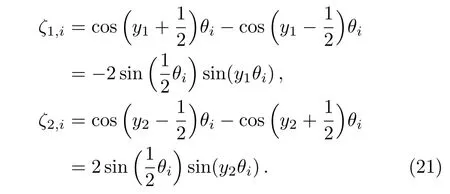
where(readζx1,iasζ1,i,ζx2,iasζ2,i)

Supposingλiand¯λiare the roots of the characteristic equation forX(i)k,from(20)we obtain(3).Next,we consider the solution of(20)when the injection of currentJis atd1(x1,y1)and the exit of currentJ
is atd2(x2,y2).We obtain the piecewise solutions

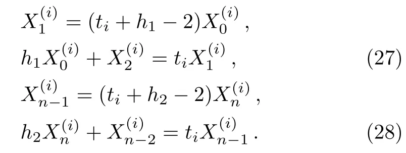
We conduct the same matrix transformation as used in(13),applyingPmto(11)and(12)on the left-hand sides,we are led to

From the above equations we can obtain after some algebra and reduction the two exact solutions ofX(i)x1andX(i)x2needed in our resistance calculation(5).
3.4 Analytical Solutions of the Matrix Equation
In this section we are going to derive the exactsolution ofby means of Eqs.(20)–(28).Substituting(27)into(22)to eliminate


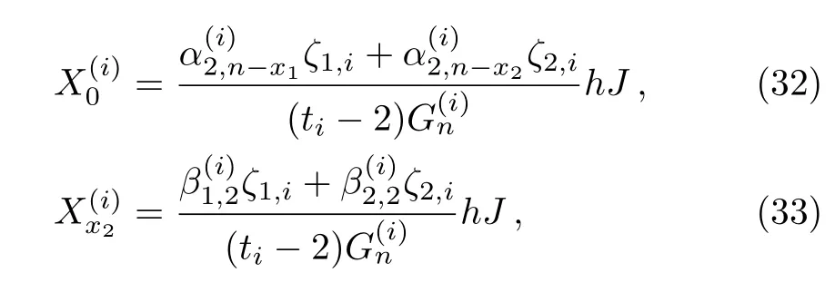
Fori≥2 to obtain the key parametersandneeded in our resistance calculation(5),we also need several independent equations.Sincesatisfy(30),andsatisfy(26),we therefore obtain four independent equations.Together with(25)and(31)we have six independent equations relating the six unknownsThus we obtain after some algebra and reduction the solution ofandneeded in the process of calculating resistance(one can refer Ref.[35])


The above conclusions are based oni≥2.Next we will consider the case ofi=1.When we just consideri=1,according to the nature of cycle shown in Fig.1,we have


3.5 Derivation of the Resistance Formula
According to the matrix equationin Eq.(18)gives

Using(37)withk=x1we achieve the following equation

Substituting(36)into(38)yields


Substituting(39)and(40)into(5),we obtain


Finally,we obtain the main result(4)by further substituting(21)into(42).
4 Applications of the Main Formula
Formula(4)is a general expression which is concise and significant but complicated to understand,we will give several special cases from(4)to understand its application and meaning.Whenh1andh2,mornare special number values,from Eq.(4)we have the following special cases.Cases 1Whenn→∞,x1,x2→∞withx1−x2finite,we have equivalent resistance in the semi-in finite network

The derivation process is as follows.
In the case ofn→∞withmfinite.From(1)and(2)we have

From Eq.(3)we knowλi>1>¯λi>0,thus

Substituting(45)into(4),we obtain(43)after usingCase 2Whenm,n→∞,butx1−x2andy1−y2are finite,the equivalent resistance between any two nodesd1(x1,y1)andd2(x2,y2)in an in finitem×nresistor network can be written as

We first refer an integral theory:Ifθk=(k−1)π/m,we have Δθk=θk+1−θk=π/m.In the limit ofm→∞,we have

which is an identity valid for any nonsingular functiong(θk).
According to the identity transform of a trigonometric function,we have

Whenm→∞andy1,y2→∞,we must transform

wherep,q≪mare integers,andp−q=y1−y2are finite.Asθk=(k−1)π/m,we have

Thus

Taking limit ofm→∞in(43),meanwhile applying(47)and(48)to(43),we therefore obtain(46).
Please note that formula(46)shows the resistance of the in finite resistor network has nothing to do with the boundary conditions.Thus formula(46)is a general formula of the in finite two-dimensional resistor network with arbitrary boundaries.
Case 3When noded1=(x,0)is atXaxis,andd2=(x,y2)is an arbitrary node,from(4)we have equivalent resistance

Case 4Whend1=(0,y1)andd2=(0,y2)are both at the left edge,from(4)we have equivalent resistance

Case 5Whenn→∞,withx1=x2=0,from(50)we have equivalent resistance

Case 6Whenm,n→∞,withx1=x2=0,applying(47)to(51),we have equivalent resistance

Case 7Whend1=(0,y1)is at the left edge,andd2=(n,y2)is at the right edge,from(4)we have equivalent resistance

resistance

Case 8Whend1=(x1,y)andd2=(x2,y)are both at the same horizontal axis,from(4)we have equivalent resistance

Case 9Whenh1=h2=1,from(4)we have equivalent resistance

Case 10Whenh2=0,the Fig.1 degrades into Fig.2,from(4)we have equivalent resistance
Case 11Whenh1=h2=0,from(4)we have equivalent resistance

Case 12Whenh1=2,h2=0,from(4)we have equivalent resistance

The above twelve cases show our main formula have good applications and can deduce a lot of new results.In the following we are going to continue giving several results of a simple example to test the reliability of the formula.
Case 13Whenm=2,Fig.1 degrades into a non-regular 2×ncylindrical network with a zero resistor axis and the left-right arbitrary boundaries as shown in Fig.4.When we evaluate the resistance between nodesAk(k,0)andBk(k,1),Bk(0,1)andBk(k,1),we havey1=0,y2=1.Thus fromθi=(i−1)π/mwe haveθ2=π/2,andS1,i=sin(y1θ2)=0,S2,i=sin(y2θ2)=1,and

From Eq.(49)we obtain the resistance


In particular,whenh1=h2=1,and defineλ2=eL,¯λ2=e−L,from Eqs.(61)and(62)we have whereλ2and¯λ2are given by(60).It is easy for us to test the correctness of Eqs.(61)–(64)if we taken=1,2,3,4.For example,from(61)we obtain equivalent resistance

From Eq.(62)we obtain equivalent resistance


Fig.4 A 2×n cylindrical network with a zero resistor axis and two arbitrary boundaries.The rest of the resistors are r and r0.
We have verified these results by carrying out explicit calculations based on the actual circuit.In fact,our conclusions are necessarily perfect since all the process of algebra and reduction are strict and self-consistent.
5 Summary and Discussion
We derived a general formula of a non-regular cylindricalm×nresistor network with a zero resistor axis and two arbitrary boundaries by using Tan’s RT method to the network.Our researches in this paper and the previous studies[26−37]illuminate that computation of resistance using the RT method is always effective in the face of the resistor network with complex boundary conditions.All of researches show the boundary conditions of the resistor network is a very important problem,which affects the behavior of finite network,such as from case 1 to case 12 all of the different resistance formula are from the general formula(4),just because the resistance for mulae are changed with the change of the boundary conditions.We illustrate a simple example of case-13 to test the correctness of our result.We know formula(4)is concise and symmetrical because of excellent characteristics of the RT method and several good parameters are defined by Eqs.(1)and(2).These exact analytical solutions provide the significant theoretical for mulae for the interdisciplinary research and applications in physics,mathematics,biology,chemistry,and numerical studies of model systems,and so on.
The reason why the Green’s function technique and the Laplacian matrix approach are invalid to resolve the non-regular network of Fig.1 is that they depend on the two matrices along two directions,besides matrix(10),there also is another matrix with two arbitrary elements ofr1andr2when we set up a matrix along the horizontal directions,which is impossible for us to obtain the explicit eigenvalues and eigenvectors of a matrix with arbitrary elements.
In addition,the RT method can be extended to impedance networks,since the Ohm’s law based on which the method is formulated is applicable to impedances.Such as the grid elementsr,r0andr1,r2can be either resistors or impedances,we can therefore study them×ncomplex impedance networks by means of the RT method.
[1]G.Kirchhoff,Ann.Phys.Chem.148(1847)497.
[2]S.Kirkpatrick,Rev.Mod.Phys.45(1973)574;B.Derrida and J.Vannimenus,J.Phys.A 15(1982)L557;A.B.Harris and T.C.Lubensky,Phys.Rev.B 35(1987)6964.
[3]C.Pennetta,E.Al finito,L.Reggiani,F.Fantini,I.De-Munari,and A.Scorzoni,Phys.Rev.B 70(2004)174305.
[4]S.Katsura and S.Inawashiro,J.Math.Phys.12(1971)1622.
[5]Woong Kook,Adv.Appl.Math.46(2011)417.
[6]P.G.Doyle and J.L.Snell,Random Walks and Electrical Networks,The Mathematical Association of America,Washington,DC(1984).
[7]S.Redner,A Guide to First-Passage Processes,Cambridge University Press,Cambridge(2001).
[8]D.J.Klein and M.Randi,J.Math.Chem.12(1993)8195.
[9]W.J.Xiao and I.Gutman,Theor.Chem.Acc.110(2003)2849.
[10]N.Sh.Izmailian and M.C.Huang,Phys.Rev.E 82(2010)011125.
[11]N.Sh.Izmailian and C.K.Hu,Phys.Rev.E 76(2007)041118.
[12]J.P.Keating,N.Linden,J.C.F.Matthews,and A.Winter,Phys.Rev.A 76(2007)012315.
[13]C.P.Goodrich and A.J.Liu,Phys.Rev.Lett.109(2012)095704.
[14]N.Sh.Izmailian and R.Kenna,Phys.Rev.E 84(2011)021107.
[15]J.Cserti,Am.J.Phys.68(2000)896.
[16]J.H.Asad,J.Stat.Phys.150(2013)1177.
[17]J.H.Asad,A.J.Sakaji,R.S.Hijjawi,and J.M.Khalifeh,Mod.Phys.Lett.B 24(2010)695.
[18]J.H.Asad,Mod.Phys.Lett.B 27(2013)151350112.
[19]J.H.Asad,A.A.Diab,R.S.Hijjawi,and J.M.Khalifeh,Eur.Phys.J.Plus 128(2013)13002.
[20]F.Y.Wu,J.Phys.A:Math.Gen.37(2004)6653.
[21]W.J.Tzeng and F.Y.Wu,J.Phys.A:Math.Gen.39(2006)8579.
[22]N.Sh.Izmailian,R.Kenna,and F.Y.Wu.J.Phys.A:Math.Theor.47(2014)035003.
[23]N.Sh.Izmailian and R.Kenna,J.Stat.Mech.9(2014)1742.
[24]N.Sh.Izmailian and R.Kenna,Chin.J.Phys.53(2015)126.
[25]J.W.Essam,N.Sh.Izmailian,R.Kenna,and Zhi-Zhong Tan,R.Soc.open Sci.2(2015)140420.
[26]Z.Z.Tan,Resistance Network Model,Xidian Univ.Press,Xi’an(2011)(in Chinese).
[27]Z.Z.Tan,L.Zhou,and J.H.Yang,J.Phys.A:Math.Theor.46(2013)195202.
[28]Z.Z.Tan,J.W.Essam,and F.Y.Wu,Phys.Rev.E 90(2014)012130.
[29]J.W.Essam,Z.Z.Tan,and F.Y.Wu.Phys.Rev.E 90(2014)032130.
[30]Z.Z.Tan and J.H.Fang,Commun.Theor.Phys.63(2015)36.
[31]Z.Z.Tan,Chin.Phys.B 24(2015)020503.
[32]Z.Z.Tan,L.Zhou,and D.F.Luo,Int.J.Circ.Theor.Appl.43(2015)329.
[33]Z.Z.Tan and Q.H.Zhang,Int.J.Circ.Theor.Appl.43(2015)944.
[34]Z.Z.Tan,Int.J.Circ.Theor.Appl.43(2015)1687.
[35]Z.Z.Tan,Phys.Rev.E 91(2015)052122.
[36]Z.Z.Tan,Scientific Reports 5(2015)11266.
[37]Z.Z.Tan,Chin.Phys.B 25(2016)050504.
 Communications in Theoretical Physics2017年3期
- Communications in Theoretical Physics的其它文章
- Self-similar Solution of a Cylindrical Shock Wave under the Action of Monochromatic Radiation in a Rotational Axisymmetric Dusty Gas
- Solutions to Forced and Unforced Lin–Reissner–Tsien Equations for Transonic Gas Flows on Various Length Scales
- Electrostatic Surface Waves on Semi-Bounded Quantum Electron-Hole Semiconductor Plasmas
- Proton Beam Generated by Multi-Lasers Interaction with Rear-Holed Target
- Quantum Spin Transport in Rashba Spin-Orbit-Coupled Graphene Nanoflakes∗
- Hypergeometric Series Solution to a Class of Second-Order Boundary Value Problems via Laplace Transform with Applications to Nanofluids
