
Optimal heat release shaping in a reactivity controlled compression ignition(RCCI)engine
2017-12-26 09:28:37CarlosGUARDIOLABenjamPLAAntonioGARCIAVicenteBORONAT
Control Theory and Technology 2017年2期
Carlos GUARDIOLA,Benjamın PLA,Antonio GARCIA,Vicente BORONAT
CMT-Motores Te´rmicos, Universitat Polite`cnica de Vale`ncia, Valencia, Spain
Optimal heat release shaping in a reactivity controlled compression ignition(RCCI)engine
Carlos GUARDIOLA,Benjamın PLA†,Antonio GARCIA,Vicente BORONAT
CMT-Motores Te´rmicos, Universitat Polite`cnica de Vale`ncia, Valencia, Spain
The present paper addresses the optimal heat release(HR)law in a single cylinder engine operated under reactivity controlled compression ignition(RCCI)combustion mode to minimise the indicated specific fuel consumption(ISFC)subject to different constraints including pressure related limits(maximum cylinder pressure and maximum cylinder pressure gradient).With this aim,a 0-dimensional(0D)engine combustion model has been identified with experimental data.Then,the optimal control problem of minimising the ISFC of the engine at different operating conditions of the engine operating map has been stated and analytically solved.To evaluate the method viability a data-driven model is developed to obtain the control actions(gasoline fraction)leading to the calculated optimal HR,more precisely to the optimal ratio between premixed and diffusive combustion.The experimental results obtained with such controls and the differences with the optimal HR are finally explained and discussed.
Diesel engine,RCCI,combustion analysis,optimal control
1 Introduction
Increasing concern about environmental issues and specially the each time more stringent emission limits imposed by regulations are driving a substantial evolution in the automotive industry.From a powertrain perspective,the automotive sector follows three different approaches to strongly reduce pollutant emissions from vehicles while keeping or even increasing performance to fulfil customers demands[1],namely:electrification,after-treatment and combustion process improvement.Electrification allows to reduce fuel consumption and emissions by reducing,or potentially removing,the use of the internal combustion engine(ICE)at low efficiency conditions.Different technologies leading to powertrain electrification have reached maturity and its introduction in commercial vehicles is a reality while cost is still an issue.After-treatment is aimed to reduce the pollutant emissions at the engine exhaust by means of chemical(catalysts)and mechanical(filtering)methods at the expense of some penalty in cost and eventually in fuel consumption.Finally,the last approach is to improve fuel consumption and emissions at the source,i.e.,at the ICE.
Amongst other techniques,low temperature combustion(LTC)concepts has demonstrated to be a promising technique,able to keep,or even improve,the engine efficiency of compression ignition(CI)engines while substantially reducing the NOxand soot emissions[1],mitigating after-treatment requirements and then contributing to regulation limits.This concept is based on the self-ignition of premixed lean mixtures burning under low tempeature combustion.Providing a complete review of all the combustion concepts related to LTC exceeds the scope of this paper,it will just be mentioned that the LTC concept has been applied by means of different techniques leading to an extensive nomenclature that includes terms such as HCCI,CAI,PCCI,PPCIorMK amongst others.The interested reader may consult[1]and references within for a complete description of such techniques.In any case,according to different publications[2–6],the reactivity controlled compression ignition(RCCI)is one of the most promising LTC techniques.This concept is based on promoting a premixed combustion by injecting sequentially two fuels with different reactivity level.In this sense,a low reactivity fuel(typically gasoline)is injected in the engine ports or in the cylinder during the intake or early compression stroke,while a direct injection of a high reactivity fuel(typically diesel)is done in the combustion chamber[7–9].Thus,the RCCI combustion is based on modifying the fuel blend to adjust the desired fuel reactivity that leads to a combustion process with low emissions and high efficiency[10].
To some extent,the potential of RCCI combustion relays on the increase of the degrees of freedom of the system,while in other combustion strategies the fuel reactivity is fixed (or a priori defined) with RCCI combustion this becomes an additional control variable through the election of the proper Gasoline Fraction(hereinafter GF)[1,11].Thus,the potential of RCCI involves some penalty in terms of control effort.In addition to the traditional injection variables(injection pressure,number of injections,and injection timing)the percentage of gasoline and diesel in the injected fuel may be assessed.
In this scenario,the present paper contributes to the selection of the proper GF and then the simplification of the calibration process by means of a model-based shaping of the heat release(HR)law.Fuel consumption minimisation criteria, with some restrictions on the pressure rise rate and the maximum cylinder pressure,is applied in the HR shaping process.Some authors[11,12]point out that the GF,and more particularly the premixed energy rate(PER)plays a key role in the HR shape,so the optimal HR traces obtained from the model are mapped with the GF to be applied in the experimental engine by means of a database model.
In the present work,the HR shaping has been carried out by means of the application of optimal control(OC)theory,that has been recently employed by[13–16]to find the optimal HR that minimises fuel consumption considering different constraints.The objective of the cited works is the assessment of the engine efficiency but also to evaluate possible ways of improvement.In particular,[13,14]address the fuel consumption minimisation under maximum pressure and knock restrictions while[15]includes NOxemissions.Finally,[16]uses variational analysis to find the optimal spark advance in a spark ignited engine.In any case,previous works point out that OC is an useful tool to assess the efficiency of a given engine since:
.The optimality assures that the best possible combustion scenario for comparison is used.On the contrary,traditional methods to evaluate the efficiency rely on arbitrary combustion laws such as constant volume,that are too simple and idealistic.
.Restrictions related to non-energy based parameters can be taken into account.This is an important limitation of the traditional approach used to assess the engine efficiency consisting in the application of the first and second law of thermodynamics in order to perform an energy and exergy balance[17].In this sense,OC allows to easily include parameters that are not strictly related with energy such as the maximum cylinder pressure derivative or NOxemissions.In general,OC may address any criteria or constraint if a suitable model exists.
According to the previous ideas,the paper is structured as follows:Section 2 introduces the experimental facility and modelling tools employed in this work.The experimental facility has been used to identify the combustion model parameters and to validate the OC laws leading to the fuel consumption minimisation.Meanwhile,the model employed in the present paper is a 0D model aimed to represent the processes in the high pressure loop of an ICE, i.e., between the intake valve closing(IVC)and exhaust valve opening(EVO).The model inputs are the rate of heat release(RoHR),the volume evolution,the gas conditions at the IVC and the wall temperatures.Section 3 deals with the calculation of the optimal HR shaping,including both the problem formulation in a proper way to be solved by means of OC and the proposed solution.In Section 4,optimal HR and the corresponding fuel consumption obtained from the model are analysed.The implementation of such optimal HRs in the actual engine through the mapping of the GF is also described in Section 4.Then,the fuel consumption obtained in the experimental facility after the application of the proposed strategy and its difference with the modelling results are presented and discussed.Finally,the most important contributions of the paper are outlined in Section 5.
2 Experimental facility and modelling tools
2.1 Test cell and engine description
The experimental part of this work has been carried out in a medium-duty diesel engine whose main characteristics appear in Table 1.
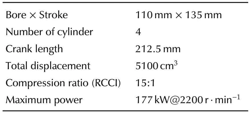
Table 1 Engine set up.
The series 4 cylinder engine has been modified in order to be operated as a single-cylinder engine,i.e.,the first cylinder is the focus of the present study and can be operated in RCCI mode while the other 3 cylinders work with the engine series configuration.In this sense,the isolated cylinder behaves like a single cylinder engine while the three remaining cylinders,which are driven by the standard calibration,allow keeping the mechanical balance.Similar test cell configurations have been previously used in[18,19].
The isolated cylinder is provided with fresh air from a tank whose pressure and temperature conditions can be controlled.In a similar way,the back pressure produced by the turbine in the standard engine is replicated by means of a controlled valve in the exhaust of the isolated cylinder.An independent EGR circuit is also used for the isolated cylinder.In this case,part of the exhaust gases are passed through an EGR conditioner,where the humidity is removed and the desired pressure and temperature is achieved before being introduced at the intake manifold of the isolated cylinder.
The complete engine,and particularly,the cylinder under study has been fully instrumented with flow,pressure and temperature sensors.An Horiba Mexa-One D1 EGR has been used to measure the concentration of NOx,CO,unburned HC and exhaust CO2concentrations that allow to calculate the engine emissions.Regarding the in-cylinder pressure,the signal was measured with a Kistler 6125C pressure transducer coupled with a Kistler 5011B10 charge amplifier.A shaft encoder with 1800 pulses per revolution has been used to obtain a 0.2°resolution of the in-cylinder pressure signal.
All sensors, transducers and analysers were calibrated by applying traditional or manufacturers recommended methods.The complete scheme and description of the facility can be found in[12].
2.2 In-cylinder process modelling
The experimental facility previously presented allows measuring the indicated parameters of the cylinder under study.In particular,properly processing the incylinder pressure(ICP)signal and the amount of fuel injected(both diesel and gasoline),the indicated specific fuel consumption(ISFC)of the engine may be calculated.In the same way,the ICP signal allows to check what is the maximum pressure(pmax)and maximum pressure rise(dpmax)achieved.Other interesting parameters to assess the engine performance and for the engine ICP based control(e.g.,CA50,combustion duration,...)can be equally obtained from the ICP signal.In any case,the single-cylinder-like nature of the facility limits the assessment of the engine performance to indicated values.
In the same way,the model used should attain a detailed description of the indicated performance of the engine.It is worth to note that despite of rigorous and detailed,the model used should be simple enough to allow the application of OC techniques without a prohibitive computational cost.Under this scope,authors have decided to model the compression,combustion and expansion processes of the engine,i.e.,between intake valve closing(IVC)and exhaust valve opening(EVO),as a process in a closed system with a single substance whose properties evolve with the thermodynamic conditions.
The pressure and temperature evolution of the fluid inside the cylinder is calculated from an energy balance and the ideal gas equation of state.In particular,the application to the first law of thermodynamics to a closed system with a perfect gas reads:
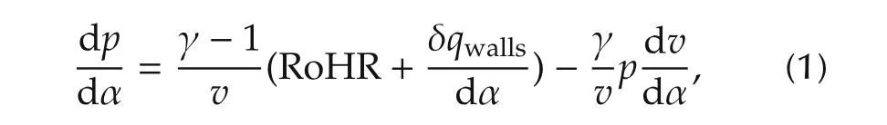
where υ is the specific volume in the cylinder that is a priori known from the crankshaft-piston mechanism kinematics, γ is the heat capacity ratio, RoHR andwallsrepresent the heat released during the combustion process and the heat transfer to the cylinder walls respectively.Note that the dependence of the variables on the crank angle(α)has been omitted for the sake of clarity.
The combustion process is modelled as a heat addition to the system(RoHR),that should be properly chosen in order to minimise the ISFC while fulfilling the pressure constraints.Accordingly,the evolution of the heat released during the combustion is modelled as

where mfis the total fuel injected during the cycle,LHV stands for the lower heating value of the fuel and u,which is the control variable,represents the fuel burning rate,i.e.,the derivative of the fuel mass fraction burnt respect to the crank angle.Despite using different fuels,as far as diesel and gasoline have a similar LHV an unique value has been used for both.Otherwise an additional state,i.e.,the type of fuel injected,should be added to the problem.
Regarding the heat transferred to the cylinder walls,it is modelled as a function of the temperature difference between the gas and the walls through an apparent area and heat transfer coefficient.A Nusselt-like correlation,in particular a version of the well known Woschni approach[20],proposed in[17]has been used to obtain the evolution of the heat transfer coefficient during the engine cycle as
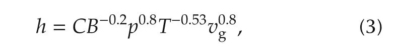
where C is an empirical constant(in the case at hand 0.12),B is the piston bore,p and T represent the pressure and temperature evolution in the combustion chamber and υgis the gas velocity obtained from the following correlation:
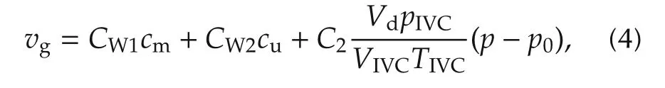
where cmand cuare the mean piston speed and the tangential flow velocity due to swirl respectively,pIVC,VIVCand TIVCare the cylinder pressure,volume and temperature at the intake valve closing,Vdis the cylinder displacement,p0is the pressure evolution in motoring conditions and CW1,CW2and C2are constants to be calibrated.
Provided that the fluid conditions at the IVC and the volume evolution during the engine cycle are known,equation(1)can be integrated from the IVC to the EVO in order to obtain the pressure evolution in the cylinder as a function of the sequence in u applied.
3 Optimal heat release shaping
The aim of the paper is to calculate the optimal Heat Release(HR)sequence to minimise the ISFC in an RCCI engine subjected to some mechanical constraints,namely a the maximum cylinder pressure and the maximum pressure rise.Previous works[15]have addressed the optimisation problem including a constraint on the NOxemissions for a CI combustion,however,in this case such a restriction is neglected because of two main reasons:
.Experimental results obtained in the engine under study[7]show that NOxemissions in the RCCI mode are considerably below CI results and certainly below the considered limitation for EURO VI(0.4g/kWh).The lower emissions in the RCCI mode are explained by a better air fuel mixing and lower combustion temperatures.
.While extensive literature addressing the thermal NOxproduction exists[21,22],there are few works about low computational models for non-thermal NOxformation mechanism.Although thermal mechanism does represent most of NOxproduced by the diffusive flame combustion of a conventional CI combustion,the thermal mechanism is inadmissible as a predictive model for LTC modes as RCCI[23].More complex mechanisms such as such as Prompt and N2O intermediate should be combined with the thermal formation to obtain accurate results.The lack of models with a low number of states for those mechanisms prevents the consideration of a NOxrestriction in the optimal HR design.
3.1 Problem formulation
To deal with the previous objective,consider the following general dynamic equation of the system:
According to the previous paragraph,the problem examined in the present paper can be formally stated as finding the sequence of burning rates(control policy u)that minimises the indicated specific fuel consumption(ISFC)over the engine thermodynamic cycle between the IVC and EVO for an operating point defined as the set of engine speed,fuel injected and cylinder gas conditions at the IVC(temperature,pressure,composition).Given that:

as the fuel injection(mf)is included in the operating point definition,minimising the ISFC is equivalent to maximising the indicated work(Wi).For the sake of formulation simplicity,the last option has been chosen.Therefore,the merit function to maximise is
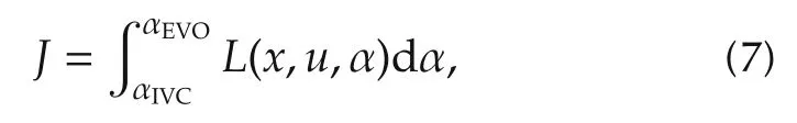
where L is the so-called Lagrangian function of the problem.As far as the function J represents the work done along the cycle,the associated Lagrangian function L may be defined as
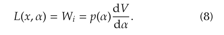
Note that,in the case at hand,since the cylinder pressure is a state of the system,and the volume trajectory is fixed,the value of the Lagrangian is independent of the control variable u.
It should be noted that the obtained HR should maximise the function(7)but also hold the following constraints:
.The maximum cylinder pressure should be below certain limit to avoid engine damage.

.The maximum cylinder pressure derivative should be below certain limit to avoid engine damage and excessive noise emissions.

.The fuel burnt during the engine cycle should not exceed the total amount of fuel injected.
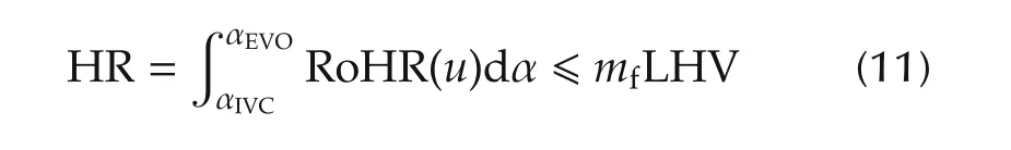
or making use of expression(2),in terms of the control variable:
where obviously,to maximise the indicated work all the fuel injected should be burnt,so the equal sign prevails.
The optimisation problem is completed with the initial conditions,represented by the in-cylinder pressure,but also admitted mass and composition at the IVC,and the cylinder volume evolution,which,from a control perspective,is a known disturbance.
3.2 Proposed solution
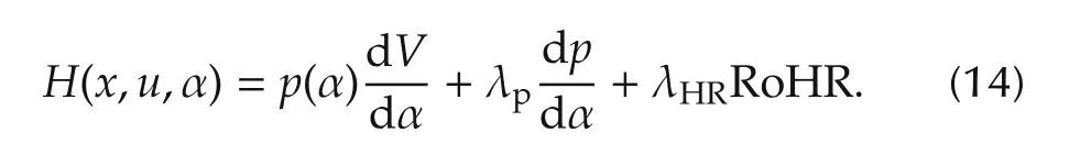
In order to solve the previously stated optimal control problem,the constraints on the system dynamics represented by expression(5)(or more specifically by equations(1)and(2))should be adjoined to the Lagrangian(equation(8))by introducing the co-state vector λ.Accordingly,the following Hamiltonian(H)can be constructed:

In the case at hand,introducing expression(8)and considering the states of the problem,H becomes
Provided that L does not depend on the control action(u)and equations(1)and(2)are both linear in u,H should be also linear in u,and then,its maximum occurs at one of the extreme values of u.In particular,the minimum value u can achieve is 0,while the maximum value of u is limited at each angle by the RoHR leading to the maximum pressure derivative,the maximum allowed in-cylinder pressure or the burning of all the available fuel.
The previous reasoning leads to the so called bangbang control.In other words,the way to minimise the fuel consumption is to burn nothing until an angle,and afterwards,burn the maximum amount of fuel possible according to previous limits.The switchover angle¯αis to be determined.In this sense,one can assure that the following control strategy is optimal:
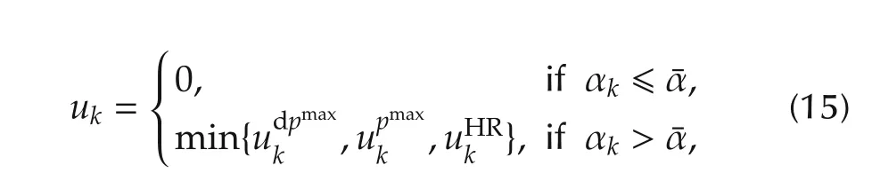
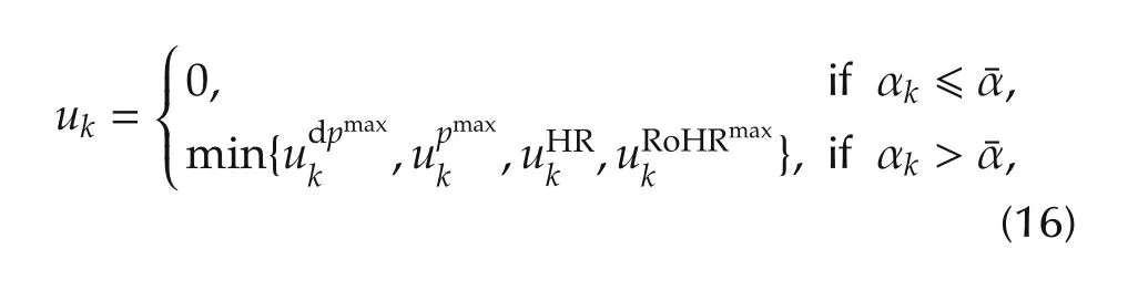
The grey line in Fig.1 shows the evolution of the optimal cylinder pressure trace(upper plot),HR(medimum plot)and RoHR(lower plot).As far as the model input is the RoHR,there is not limitation in the way the fuel is burnt,which leads to the non-physical meaningful fact of sudden increases and reductions in the RoHR that are not experimentally feasible.Independently on the injection strategy,the engine has some physical limitations that prevent a fast combustion during the late expansion stroke,when the amount of fuel and available air is reduced.Those limitations are related to the engine geometry and matching between piston and injector[25,26],so are outside of the control scope.In order to deal with inability of the model to represent such limitation in the RoHR,the following strategy has been used:an artificial constraint on the maximum RoHR has been introduced as a function of the HR.In this sense,Fig.2 shows the evolution of the RoHR as a function of the HR for a wide set of operating conditions with different settings.One can observe that while in central part of the plot(HR ranging from 0.1 to 0.8)the RoHR follows completely different evolutions,at the extremes,obviously all RoHR traces progressively converge to 0.In the case at hand,the maximum measured values of the RoHR at the extreme HRs(black line)have been used as additional constraints to the control action RoHR.Accordingly,equation(16)is the final version of the control strategy applied:
The black line in Fig.1 shows the optimal results with the proposed approach. It is easy to see the zones where the combustion process hits the different restrictions on the control action.The first and final phases of the combustion process are limited by the restriction on the maximum RoHR.After the initial combustion phase,the RoHR is limited by the maximum pressure derivative and once the maximum allowed in-cylinder pressure is reached,the optimal HR rate is that keeping constant the in-cylinder pressure until the RoHR restriction appears at the end of the process.
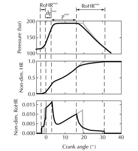
Fig.1 Optimal state(p and HR)and control action(RoHR)evolution for a given operating condition.−−:Optimal solution without RoHR restrictions.−−:Optimal solution with RoHR restrictions according to Fig.2.
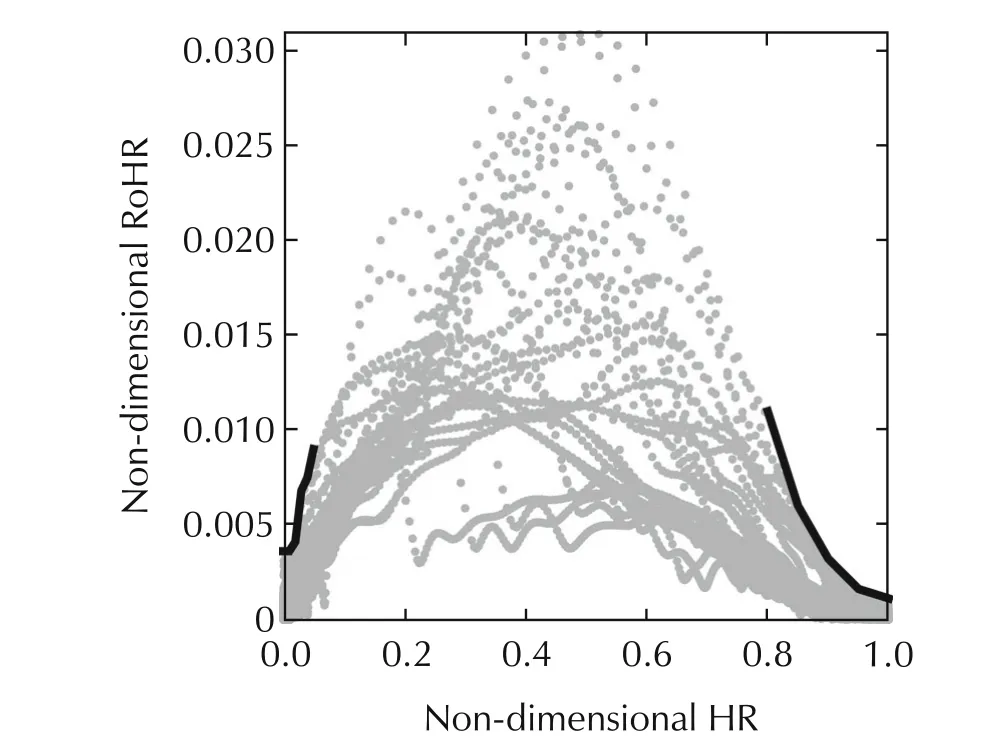
Fig.2 Experimental values of RoHR depending on the HR at a wide set of operating conditions of the RCCI engine(•)and RoHR limits depending on HR imposed to the optimal control(−−).
4 Results and discussion
Fig.3 shows the values of the normalised ISFC obtained from the optimisation process previously described.It can be appreciated that the ISFC increases progressively from high to low loads,pointing out the effect of losses due to heat transfer that are increasingly important in relative terms as the load is reduced.Despite optimistic due to the model simplicity,results in Fig.3 provide a target ISFC to be attained with the experimental engine.With this aim,the optimal heat release laws calculated must be achieved in the real engine.Section 4.1 is dedicated to introduce the method used to achieve the designed HR laws in the experimental engine.
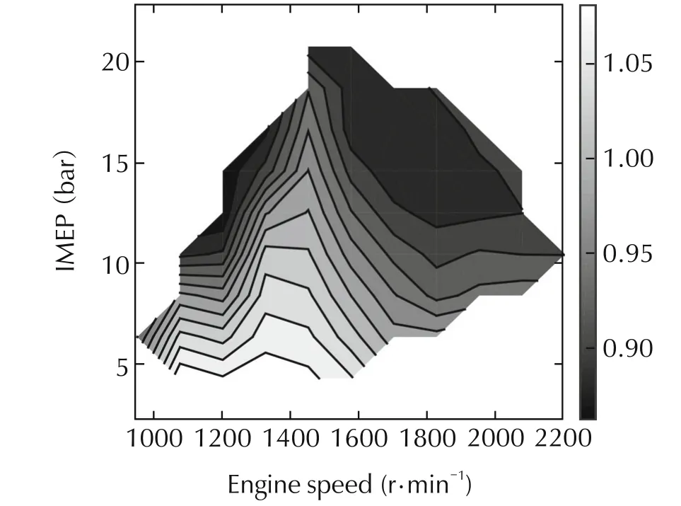
Fig.3 Modelled optimal ISFC engine map normalised with the minimum ISFC value from experiments.
4.1 Implementation of the optimal heat release law
The optimal HR in Fig.1 shows a combustion process that can be approximated by two main phases:
.Fast combustion limited by the maximum pressure gradient that may be identified with a premixed combustion process.
.Moderated combustion process limited by the maximum cylinder pressure or a maximum achievable RoHR at the late combustion process that can be identified with a diffusion combustion.
The PDR(premixed to diffusion ratio)is a parameter describing the percentage of energy released in both processes.The optimal PDR obtained for the considered operating points appears in Fig.4.It can be observed how as the load increases the PDR is reduced.The reason for that is that the premixed combustion is limited by the maximum allowed pressure derivative and maximum cylinder pressure.
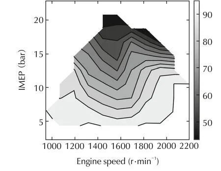
Fig.4 Optimal PDR depending on the engine conditions.
Literature[6,7]points out that the main parameter governing the PDR and therefore combustion phasing in a RCCI engine is the gasoline fraction(GF).More precisely,the GF is the main parameter defining the PDR at low-medium load,while at high loads both the GF and the diesel injection phasing play an important role on the PDR.While the PDR can be easily computed from the modelling results by weighting the contribution of both combustion phases,the GF cannot be calculated.On the contrary,the control parameter in the engine is the GF and the injection timing instead of the PDR that is in fact a result of the combustion process.To link the optimal HR calculated with the control parameters leading to the same combustion evolution in the engine,the PDR has been considered an intermediate variable such that if the model and the engine share the same PDR,then the HR evolution should be at least similar.Also,to obtain the desired PDR in the actual engine a calibration GF vs PDR has been done from experimental data obtained in a wide set of arbitrary conditions.At those arbitrary conditions,the PDR has been calculated as the percentage of fuel mass(including both)gasoline and diesel injected before the CA10(angle where the 10%of the fuel is burnt).
The correlation between the PDR calculated with this method and the GF imposed in the engine appears in Fig.5.Results show a good correlation between the applied GF and the obtained PDR(the higher the amount of gasoline,the higher the percentage of fuel burnt in premixed combustion).Results in Fig.5 do not include points below 5 bar of IMEP.At very low load conditions,despite all the fuel is burnt in premixed conditions(PDR=100%)some diesel injection is needed(GF<100)to avoid engine misfire[27].Therefore,the good correlation found in Fig.5 does hold for low load points.
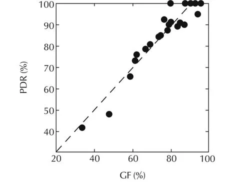
Fig.5 Correlation between the PDR and the GF imposed at different engine conditions covering the complete engine operating map.
The relation between GF and PDR shown in Fig.5may be combined with the calculated optimal PDR(Fig.4)to impose to the actual engine a GF leading to the optimal HR and then minimum ISFC.Fig.6 shows the relation between the optimal and the actual PDR obtained from such a process.Apart from some outliers mainly coming from model uncertainties,a correlation between experimental and modelled PDR may be observed.Also,it can be checked how maximum pressure and pressure derivative involve a reduction in the PDR.
Note that while the GF has been chosen with the previously described process,the current injection system has more degrees of freedom that may be resolved.In the present work the gasoline start of injection has been kept fixed at 340°before the top dead centre while injection duration has been adjusted to fit the amount of gasoline leading to the desired GF.Regarding the diesel injection,it has been separated in two events:the first one between 35 and 60°before the top dead centre contributing to the premixed combustion and with an important impact on the combustion timing.Then,if necessary,a second injection after the start of combustion contributing to the diffusion combustion.The injection pressure has been kept constant at 1200 bar while the exact timing has been obtained from a parametric study.
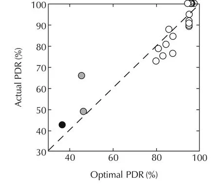
Fig.6 Correlation between optimal and actual PDR.●:Points whose experimental RoHR is limited by the maximum pressure gradient,●:Points whose experimental RoHR is limited by the maximum cylinder pressure.
Fig.7shows the experimental RoHR obtained with the GF imposed from the optimisation and the injection settings from the parametric study leading to the minimum ISFC.It can be clearly observed how as the load increases,the percentage of fuel injected in the first of the two diesel injections is progressively reduced to avoid pressure limitations.In this sense,all the fuel is injected clearly before the start of combustion in the point at low load.The first injection is progressively increased up to a maximum value that cannot be exceeded without passing the pressure gradient limit,at this point additional fuel may be introduced near the TDC in a second fuel injection(see middle plot).Then as load increases even more the first diesel injection may be progressively reduced since combustion chamber conditions lead to early combustion that exceeds the pressure rise limits.As the first diesel injection is progressively reduced the second one increases accordingly.As it can be observed in the top plot of Fig.7,for the case of the engine operating at full load,a single diesel injection near the TDC acts as a combustion trigger,while most of the diesel fuel injected is burnt in a diffusion flame.
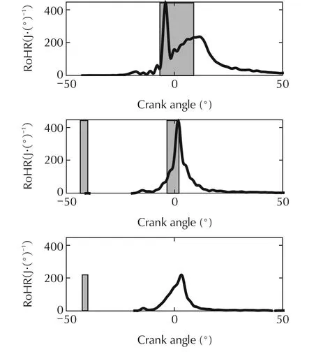
Fig.7 Experimental RoHR obtained with the optimised GF for operating points with 1500r·min−1and low load(low plot),medium load(medium plot)and full load(top plot).The grey areas represent the diesel injection events.
4.2 efficiency assessment
Fig.8 shows the difference between the optimal and the experimentally obtained ISFC depending on the engine operating point.It can be observed how this difference ranges from 5g/kWh at low loads to 25g/kWh at high loads.The reason for the obtained difference may be justified by the evolution of the actual and the optimal HR as shown in Fig.9.
At low load,the difference between the optimal and the actual HR is focused on the initial phases of the combustion process:while the optimal HR start around the TDC,the actual one starts earlier leading to important pressure levels during the compression stroke that damage the engine efficiency.Despite both optimal and actual HR evolutions have the same PDR,the actual engine is not able to perform a combustion exactly equal to the one provided by the model. In fact, delaying the combustion by retarding the diesel injection will lead to a late and slow combustion with lower efficiency.The RoHR evolution during the intermediate and last phases of the combustion process is quite similar between the optimal and the actual cases,so it is the maximum pressure achieved and the pressure evolution during the expansion stroke.Note that the maximum pressure achieved is far below the limit in both cases,so the maximum pressure constraint is not active.
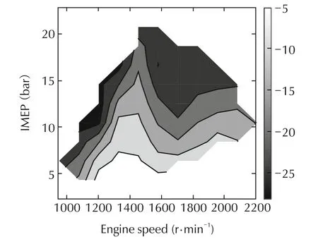
Fig.8 Difference ΔISFC(g/kWh)between the optimal and the actual ISFC depending on the engine operating point.
Similar results can be observed at medium load,where both the optimal and experimental combustion processes are eminently premixed,and while there are some differences in timing,pressure traces are similar.The difference in ISFC is mainly justified again by the increase in pressure during the compression stroke of the experimental case.However,in this case,it can be also observed a slight difference in the maximum pressure and the pressure during the expansion that also contributes to an increase of the ISFC in the case of the experimental evolution.
Finally,differences between pressure and RoHR traces become more evident at full load,then differences in the ISFC are justified.A similar trend in the RoHR can be observed since both cases consist of a premixed combustion followed by a diffusion phase that is aimed to keep high pressure values during the expansion stroke. As in previous cases, the experimental RoHR is advanced in comparison to the calculated one due to limitations in the combustion process that are not taken into account in the model.
In any case,the proposed methodology has been able to provide reference RoHR laws leading to minimum fuel consumption and the GF to be applied in the engine to reproduce,to some extent,those RoHR laws.
The methodology proposed also gives minimum ISFC satisfying the engine maximum cylinder pressure and pressure rise that could be achieved with an ideal injection-combustion system.Those values are useful to identify possible ways of actuation that may lead to an improvement in engine performance.In the case at hand,results show that upgrading the engine with solutions aimed to improve the late combustion allowing the engine to burnt the fuel later in the expansion stroke may reduce the ISFC up to 25g/kWh at full load.
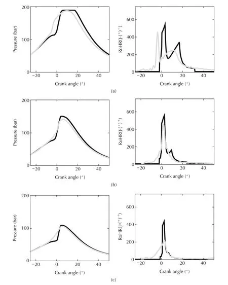
Fig.9 Optimal(−−)and experimental(−−)cylinder pressure(left)and RoHR(right)traces for operating points with 1500r·min−1 and(a)low load,(b)medium load and(c)full load.
5 Conclusions
The heat release shaping in an RCCI engine has been addressed by the application of OC.The main contributions of the paper are:
.The RoHR leading to a minimum fuel consumption with potential restrictions in the maximum pressure rise and maximum pressure achieved follows a bang-bang solution.No fuel should be burnt up to a given angle,where the maximum RoHR(fulfilling with the restrictions)is to be applied.
.There is a strong correlation between the GF and PDR that can be used to calibrate the GF of the engine to reproduce the PDR obtained from the optimisation process.
.The OC framework provides the optimal HR evolution that allow to choose the proper GF of the engine at its different operating conditions,then reducing the calibration effort.
.The ISFC obtained from OC represents a minimum boundary for the ISFC of the actual engine that cannot be exceeded,and that is more realistic than values provided by ideal thermodynamic cycles.
.The comparison of the HR evolutions obtained from experiments with those from the OP application provides insight on the systems or processes with room for improvement.In the case at hand,the analysis has pointed out that measures aimed to improve the late combustion would involve important benefits in the ISFC.
[1]F.Payri,J.M.Lujan,C.Guardiola,et al.A challenging future for the IC engine:New technologies and the control role.Oil&Gas Science and Technology–Revue D IFP Energies Nouvelles,2015,70(1):15–30.
[2]H.Yanagihara,Y.Sato,J.Minuta.A simultaneous reduction in NOxand soot in diesel engines under a new combustion system(Uniform Bulky Combustion System–UNIBUS).Proceedings of the 17th international Vienna Motor Symposium,Vienna,1996:303–314.
[3]D.A.Splitter,M.L.Wissink,T.L.Hendricks,et al.Comparison of RCCI,HCCI,and CDC operation from low to full load.THIESEL 2012conference on thermo- and fluid dynamic processes in direct injection engines.Valencia,2012.
[4]J.Benajes,J.V.Pastor,A.Garcıa,et al.The potential of RCCI concept to meet EURO VI NOxlimitation and ultra-low soot emissions in a heavy-duty engine over the whole engine map.Fuel,2015,159(1):952–961.
[5]J.Benajes,A.Garcıa,J.Monsalve-Serrano,et al.An assessment of the dual-mode reactivity controlled compression ignition/conventional diesel combustion capabilities in a EURO VI medium-duty diesel engine fueled with an intermediate ethanol-gasoline blend and biodiesel.Energy Conversion and Management,2016,123(1):381–391.
[6]S.Molina,A.Garcıa,J.M.Pastor,et al.Operating range extension of RCCI combustion concept from low to full load in a heavy-duty engine.Applied Energy,2015,143:211–227.
[7]D.A.Splitter,R.D.Reitz.Fuel reactivity effects on the efficiency and operational window of dual-fuel compression ignition engines.Fuel,2014,118(5):163–175.
[8] J.Benajes,S.Molina,A.Garcıa,et al.Effects of low reactivity fuel characteristics and blending ratio on low load RCCI(reactivity controlled compression ignition)performance and emissions in a heavy-duty diesel engine.Energy,2015,90:1261–1271.
[9] J.Benajes,S.Molina,A.Garcıa,et al.An investigation on RCCI combustion in a heavy duty diesel engine using incylinder blending of diesel and gasoline fuels.Applied Thermal Engineering,2014,63(1):66–76.
[10]J.Li,W.M.Yang,H.An,etal.Numerical investigation on the effect of reactivity gradient in an RCCI engine fueled with gasoline and diesel.Energy Conversion and Management,2015,92(1):342–352.
[11]J.Benajes,S.Molina,A.Garcıa,et al.Effects of direct injection timing and blending ratio on RCCI combustion with different low reactivity fuels. Energy Conversion and Management,2015,99(1):193–209.
[12]J.Benajes,J.V.Pastor,A.Garcıa,et al.A RCCI operational limits assessment in a medium duty compression ignition engine using an adapted compression ratio.Energy Conversion and Management,2016,126(1):497–508.
[13]F.Zurbriggen,T.Ott,C.Onder,et al.Optimal control of the heat release rate of an internal combustion engine with pressure gradient,maximum pressure,and knock constraints.Journal of Dynamic Systems,Measurement,and Control,2014,136(6):DOI 10.1115/1.4027592.
[14]L.Eriksson,M.Sivertsson.Computing optimal heat release rates in combustion engines.SAE International Journal of Engines,2015,8(3):1069–1079.
[15]L.Eriksson,M.Sivertsson.Calculation of optimal heat release rates under constrained conditions.SAE International Journal of Engines,2016,9(2):1143–1162.
[16]Y.Zhang,T.Shen.Model based combustion phase optimization in SIengines: Variational analysis and spark advance determination.IFAC-PapersOnLine,2016,49(11):679–684.
[17]F.Payri,P.Olmeda,J.Martın,et al.A new tool to perform global energy balances in DI diesel engines.SAE International Journal of Engines,2014,7(7):43–59.
[18]S.Yu,M.Zheng.Ethanol-diesel premixed charge compression ignition to achieve clean combustion underhigh loads.Proceedings of the Institution of Mechanical Engineers–Part D:Journal of Automobile Engineering,2016,30(4):527–541.
[19]D.Klos,D.Janecek,S.Kokjohn.Investigation of the combustion instability-NOxtradeoff in a dual fuel reactivity controlled compression ignition(RCCI)engine.SAE International Journal of Engines,2015,8(2):821–830.
[20]G.Woschni.A Universally Applicable Equation for the Instantaneous Heat Transfer Coefficient in the Internal Combustion Engine.SAE Technical Paper.1967:DOI 10.4271/670931.
[21]C.Guardiola,J.Lopez,J.Martın,et al.Semi-empirical in-cylinder pressure based model for NOxprediction oriented to control applications.Applied Thermal Engineering,2011,31(16):3275–3286.
[22]C.Guardiola,J.Martın,B.Pla,et al.Cycle by cycle NOxmodel for diesel engine control.Applied Thermal Engineering,2017,110:1011–1020.
[23]J.M.Desantes,J.J.Lopez,P.Redon,et al.Evaluation of the Thermal NO formation mechanism under low temperature diesel combustion conditions.International Journal of Engine Research,2012,13(6):531–539.
[24]O.Sundstrm,L.Guzzella.A generic dynamic programming Matlab function.IEEE International Conference on Control Applications/International Symposium on Intelligent Control,St Petersburg:IEEE,2009:1625–1630.
[25]J.Benajes,A.Garcıa,J.M.Pastor,et al.Effects of piston bowl geometry on reactivity controlled compression ignition heat transfer and combustion losses at different engine loads.Fuel,2016,98(1):64–77.
[26]J.Benajes,J.V.Pastor,A.Garcıa,et al.An experimental investigation on the influence of piston bowl geometry on RCCI performance and emissions in a heavy-duty engine.Energy Conversion and Management,2015,103:1019–1031.
[27]J.M.Desantes,J.Benajes,A.Garcıa,et al.The role of the in-cylinder gas temperature and oxygen concentration over low load RCCI combustion efficiency.Energy,2014,78(SI):854–868.
19 October 2016;revised 3 February 2017;accepted 8 February 2017
DOI10.1007/s11768-017-6155-5
†Corresponding author.
E-mail:benplamo@mot.upv.es.Tel.:+34 963 879 237;fax:+34 963 877 659.
This work was supported by Ministerio de Economıa y Competitividad through Project TRA2016-78717-R.
©2017 South China University of Technology,Academy of Mathematics and Systems Science,CAS,and Springer-Verlag Berlin Heidelberg

Carlos GUARDIOLAreceived the M.Sc.degree in Mechanical Engineering from the Universitat Politècnica de València(Spain)in 2000,and was honored with the First National Award by the Spanish Education Ministry.He received the Ph.D.degree in 2005 at the same university,and he develops his research activity in the CMT-Motores Termicos institute of the same university,where he serves now as Associate Professor,teaching Internal CombustionEngines. He leads research on control and diagnosis of internal combustion engines,and has been co-author of more than 100 scientific works,including books,patents and journal and conference papers.He was co-editor of“Automotive Model Predictive Control:Model,Methods and Applications”, and is member of SAE, of the Technical Committee on Automotive Control of the International Federation of Automatic Control,and of the Editorial Board of the“Proceedings of the Institution of Mechanical Engineers–Part D:Journal of Automobile Engineering”.In 2014 he received the Ralph R Teetor Educational Award by SAE International.Email:carguaga@mot.upv.es.

Benjamin PLAreceived his degree in Industrial Engineering(with focus on Mechanical Engineering)at the Universitat Polit `ecnica de Val `encia in 2004.Afterwards,he enrolled the Research Institute CMT-Motores Termicos to obtain a Ph.D.in 2009.During this process he passed through different research grants until obtaining a Lecturer position in 2008.After his Ph.D.he become assistant professor,giving lectures on Thermodynamics and Fluid-Mechanics in the Aerospace Degree of the UPV.With regards to research activities he is part of the Engine Control Research Group at CMT-Motores Termicos.His research focuses on the control and diagnosis of vehicle powertrains.E-mail:benplamo@mot.upv.es.

Antonio GARCIAreceived his Master’s degree in Energy Engineering(in 2005),Master’s degree in Internal Combustion Engines(in 2008)and Ph.D.Mechanical Engineer(in 2009)at the Universitat Politecnica de Valencia(UPV).During the last years,his research activities have focused in the field of internal combustion diesel engines.He was promoted to Assistant Professor in June 2008 at the UPV,where he is developing his teaching responsibilities in the frame of combustion fundamentals.Nowadays,he is participating in different research activities as a member of the CMT-Motores Termicos institute.E-mail:angarma8@mot.upv.es.

Vicente BORONATreceived his Master’s degree in Mechanical Engineering(in 2014)and Ph.D.-Student Mechanical Engineer(in 2015)at the Universitat Politecnica de Valencia.During the last years,his research activities have focused in the field of low temperature combustion strategies such as RCCI applied on internal combustion diesel engines.Nowadays,he is participating in Dual-Mode research activities as a member of the CMT-Motores Termicos institute.E-mail:viboco1@mot.upv.es.
 Control Theory and Technology2017年2期
- Control Theory and Technology的其它文章
- Towards to dynamic optimal control for large-scale distributed systems
- Comparison of generalized engine control and MPC based on maximum principle
- MPC-based torque control of permanent magnet synchronous motor for electric vehicles via switching optimization
- Online calibration of combustion phase in a diesel engine
- Two-degree-of-freedom H-infinity control of combustion in diesel engine using a discrete dynamics model
- Experimental investigation of control updating period monitoring in industrial PLC-based fast MPC:Application to the constrained control of a cryogenic refrigerator