
Comparison of generalized engine control and MPC based on maximum principle
2017-12-26 09:28:45AkiraOHATA
Control Theory and Technology 2017年2期
Akira OHATA
TECHNOVA Inc.,The Imperial Hotel Tower,1-1,Uchisaiwai-cho 1,Chiyoda-ku,Tokyo 100-0011,Japan
Comparison of generalized engine control and MPC based on maximum principle
Akira OHATA
TECHNOVA Inc.,The Imperial Hotel Tower,1-1,Uchisaiwai-cho 1,Chiyoda-ku,Tokyo 100-0011,Japan
Automotive engine control has been continuously improved due to the strong demands from the society and the market since introducing electronic controls but not always following control theories.Therefore,it is not easy for researchers from academia and even engineers from the automotive industry to grasp the whole aspect of engine control.To encounter the issue,important features of engine control are extracted and generalized from the standpoint of control engineering.Comparisons of the control and model predictive control(MPC)showed an outstanding performance of the control generalized from engine controls and how to apply MPC in the framework.
Automotive engine,history of engine control,control design,input constraints,time delay,model predictive control
1 Introduction
Automotive engine control has become a kind of the sophisticated systems integrating many sub-control systems such as engine start control,air charge estimation,idle speed control,torque demand control,air fuel ratio control,optimization of fuel consumption.However,it seems that there is a misunderstanding in the control engineering society that engine control is very primitive.It may be caused by many maps in engine controls.However,the technology of map is a superb implementation method to obtain the flexibility and to encounter nonlinearity.
Automotive engine controls have inherited the basic structure of the original engine control before introducing electronic controls and continuously improved due to the strong demands of fuel economy,the pressures from the exhaust gas regulations toughened year by year,and the end users.The automotive industry has not frequently reported the progress of engine control thus it can be not easy for researchers from academia and engineers from the automotive industry to know the whole aspect of engine control which manages nonlinearities,time delays,input constraints of range,steady state constraints due to knocking,misfiring,and over temperatures.Obviously,even a lack of the managements prevents the production of developed engine.It can contribute to the control engineering society that outstanding control features of automotive engine control are abstracted and generalized.
Model predictive control(MPC)has gathered great attentions in the automotive industry because it is considered that MPC can systematically satisfies requirements of automotive engine and also manage inequality state constraints due to such as knocking,misfiring,and over temperatures.There are many applications of MPC,for example idle speed control[1],thermal management[2],torque demand control[3],and drive train control[4],in the powertrain control area. There are also many applications in the hybrid vehicle control area.Almost all argue advantages of MPC.However,it is not clear what are the advantages compared with existing automotive engine controls because it is not easy to define what existing engine controls are.
In this paper,important features of existing engine control are abstracted and generalized.The generalized control is compared with two MPCs designed in this paper.The result argues that the control is superior to the designed MPC in this study and suggests how to use MPCbetter.The following section introduces a short his-tory of engine control and abstracts important features of engine control.Section 3 shows the generalization of engine control by equivalent transformations from Smith’s time delay compensator,Section 4 shows the comparisons of MPC and the generalized control,and the conclusion of this study is described in Section5.
2 Historical overview of automotive engine control
Before introducing electronic controls,mechanical devices such as a carburetor for supplying fuel,a distributor including the mechanical governor and the vacuumed diaphragm for the spark ignition were adopted for engine controls.From the standpoint of control engineering,the mechanical devices were considered as the elements of inverse model forming the feedforward control shown in Fig.1.

Fig.1 Series connection of inverse model and plant.
The control accuracy with the mechanical devices was limited inevitably.Especially,it was difficult for mechanical devices to satisfy the required accuracy from the exhaust gas emissions regulation thus feedback controls were introduced as shown in Fig.2 to fuel injection controls to regulate the air fuel ratio at the stoichiometric,accurately.The control shown in the diagram is called a two degree of freedom control(TDFC)and exactly transformed to the popular diagram shown in Fig.3.The portions of the inverse model and the feedback control had been replaced by the electronic controls and have been improved continuously beyond the product generation.It indicates that the structure of TDFC has been inherited by electronic engine controls.
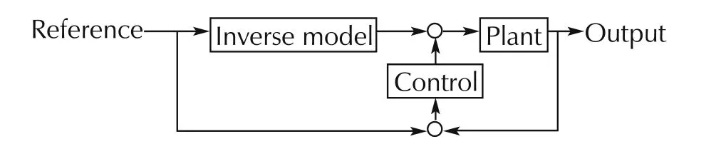
Fig.2 Two degree of freedom control.
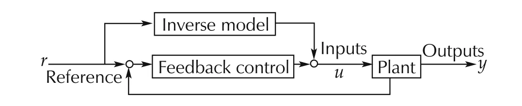
Fig.3 Popular control diagram of TDFC.
Fig.4 shows the diagram of control often found in many textbooks of control engineering.It is equivalently transformed to the diagram shown in Fig.5.It is found from Fig.5 that the feedforward and the feedback controls are same.It is the reason why TDFC gives a better control accuracy than the control shown in Fig.4.

Fig.4 Control often found in textbooks.
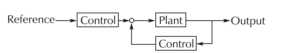
Fig.5 Diagram transformed from Fig.4.
The inverse model in Figs.2 and 3 is often approximated by a static map derived through experiments which is called a base-map.A dynamical inverse model is also applied when an accurate control is necessary.In engine controls,it strongly tends to seek accurate inverse models although lots of experiments are required to determine all inverse models.Researches from academia sometimes recommend that the feedback control should be enhanced such that experiments are reduced. However, it is not realistic because the considerable engine control accuracy must be guaranteed by the safety reason even when the sensors fail or are not active.
3 Generalized control from existing engine control
Engine controls mainly consist of tracking controls as automotive engines must quickly response to drivers’maneuvers except of the controls to keep constant engine conditions such as idle speed control(ISC).Engine control must be designed to manage the time delays,the input range constraints,compensations of aging effects and production variances,and state constraints such as knocking,misfiring,and over temperatures.It means that current engine controls have become highly sophisticated through the long term improvements.The control structure shown in Fig. 2 has a desired characteristic for engine controls because the input of the inverse model is easily managed so that the engine does not behave undesirably on the steady state conditions.
Fig.2 is equivalently transformed to Fig.6 because the series connection of the plant model and the inverse model is the identity element which indicates that the output is equal to the input.The control structure consisting of the plant,the inverse model,and the feedback control is a kind of internal model control(IMC)[5,7]which does not need a high gain feedback because the error becomes small depending on the accuracy of the inverse model.
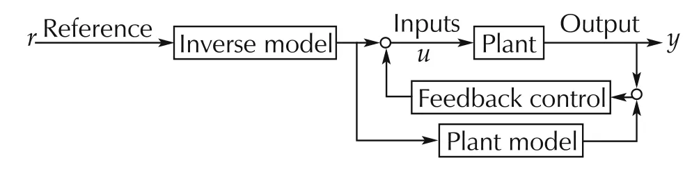
Fig.6 Equivalent transformation of the diagram in Fig.2.
3.1 Compensation of time delay
Time delay is an important factor to determine the control performance.A popular method to compensate a time delay is Smith’s time delay compensator.The plant model in Fig.4 is represented by G(s)and a time delay represented by e−sτdwhere s is the variable of Laplace transformation.Consider that C(s)denotes the control in Fig.4 thus the closed-loop system is represented by
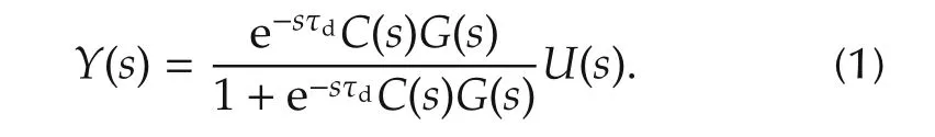
Consider the control Ct(s)which gives the same output of(1)and the closed-loop transfer function represented by
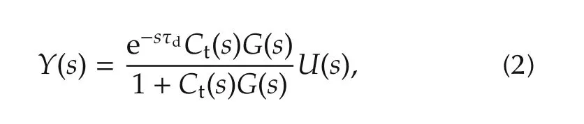
which means the time delay e−sτdtimes the transfer function of the closed-loop system without the time delay.From(1)and(2),Ct(s)is determined by

of which the diagram is drawn by Fig.7.It is equivalently transformed to Fig.8[6].
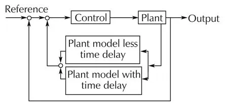
Fig.7 Smith’s time delay compensator.

Fig.8 Equivalent transformation of Smith’s time delay compensation control.
The closed-loop system consisting of “control”and“plant model less time delay”is considered as the approximated inverse model because it generates the output of“control”which forms the closed loop.Therefore,Fig.8is redrawn by Fig.9.It has the similar control structure of disturbance observer[7].The structure of IMC appears again in Fig.9 although the summation block shown with a circle is placed at a different position from Fig.6.
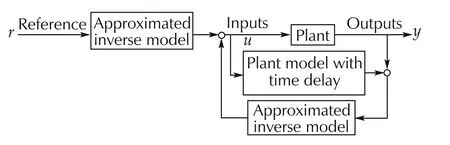
Fig.9 Simplified description of Fig.8.
Letting the the engine model is denoted by Gm,the approximated inverse model in Fig.9 be denoted by Q,the condition that both outputs of Figs.9 and 10 are equal to each other derives
Thus,the diagram of Fig.9 is transformed to the one of Fig.10 by using(4).On this control,the approximated inverse model is constructed by controlling the plant model without the time delay.Moreover,IMC makes the phase difference between the controlled engine and the model small thus the feedback control design becomes relatively easy.Therefore,PID(Proportional,Integration,and Differential)controls give the sufficient accuracy in many cases.However,the control becoems complex according to the complexity of plant model thus the approximated inverse model should be simplified.
3.2 Management of input constraints
Any actuators have the input range constraints.Such the constraints are also an important factor to determine a control performance.In engine control design,undesirable phenomena such as knocking and misfiring must not happen because they give uncomfortable feels to the driver and may give serious damages to the engine and devices.These constraints are represented by inequality state constraints[8].There are other inequality state constraints considered in engine controls such as the lower and the upper limits of catalyst temperature.
Engine behavior is represented by
where x is a state variable vector,u is a manipulation variable vector,and y is a measured variable vector.An abnormal engine operation relates to a physical background i and the normal engine operation domain is denoted by NoDiwhich is represented by

and the abnormal engine operation domain is represented by

The boundary which divides the engine operations into the normal operations and the abnormal operation is denoted by
The whole normal engine operation domain NoD is represented by

and the whole boundary is represented by∂NoD.Engines must be operated within NoD.It means that engine controls must satisfy all inequality constraints represented by(9).To manage the constraints,MPC has gathered great attentions in the automotive industry.
To deal with the constraints of production engine controls,the inequality state constraints are replaced by the input constraints with the sufficient margins because it does not cause an unstable issue when the uncontrolled engine behavior is stable.The steady state condition of(5)is represented by
It means that x∞is determined by u∞and Li(x∞,u∞)is rewritten by Li(u∞)which gives an input constraint.Thus,the automotive industry spend much time to obtain sufficient experimental data to identify the boundary ∂NoD.
3.3 Management of production variances and aging effects
Learning capabilities for production variances and aging effects and adjusting base-maps are implemented on production ECU.Fig.11 is the generalized control of existing engine control with learning capability.Generally,the adaptive capability works very slow because the production variances are fixed in an engine and the aging effect progresses very slow.Therefore,the learning capability is almost isolated from the control which immediately responds to the changes of reference and control error.

Fig.11 Generalization of tracking engine control.
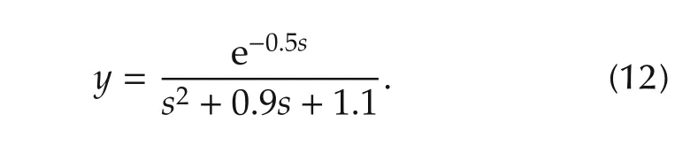
Thus, the main portion of the comparison with MPC is the control shown in Fig.10.For the purpose comparing MPC with the generalized control,a simple model with a time delay and an input range constraint is introduced.The nominal plant model is simply represented by

and the controlled model is represented by
The time delay of the plant is τd=0.5(s)and the control P in Fig.11 is a PID control.Three types of simulation was shown in Fig.12.
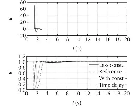
Fig.12 Control result of the generalized control from engine control.
“Reference”in Fig.12 shows the reference of the output.“Less const.”is the simulation result without the time delay and the input range constraint.“With const.”is the one without the time delay and with the input constraint.“Time delay”shows the case with the time delay and the input constraint.The control results of the best effort are shown in Fig.12.The top figure shows the inputs which are saturated at the upper limit of the input.The bottom figure shows the outputs and the reference.The result is the base of the comparison with MPC.
4 MPC design
To design MPC,(11)is transferred to the state space equation as represented by
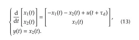
In order that the control includes the compensation of the control error by the integration of the error,the new variable ofis introduced and the augmented system is derived as represented by
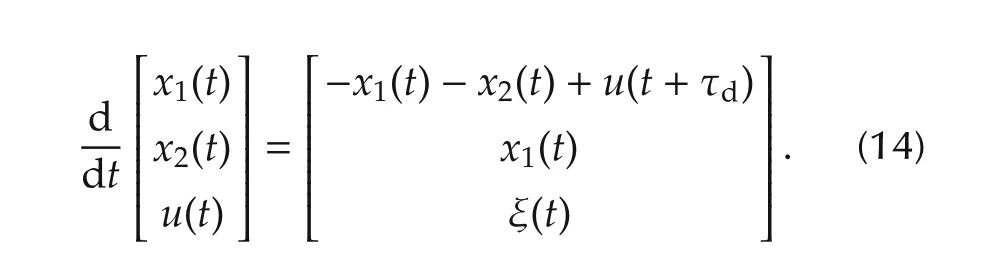
The control error of the output is denoted by e=y−yrwhere yris the reference.To derive the designed MPC which makes e(t)→ 0 when t→ ∞,the criterion is defined by
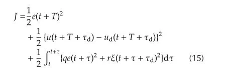
subject to(14).Thus,neglecting the upper and lower limits of the input,the corresponding Hamiltonian is represented by
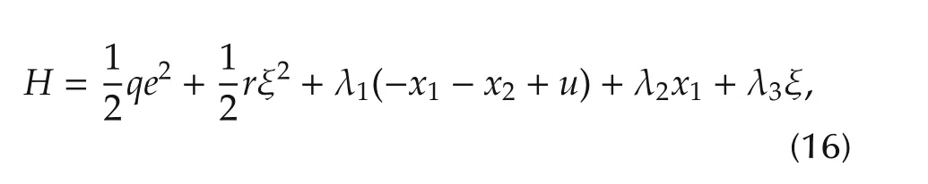
where 0<q and 0<r.Therefore,the optimal condition derives(14)with the initial condition of x1(t),x2(t)and u(t),and
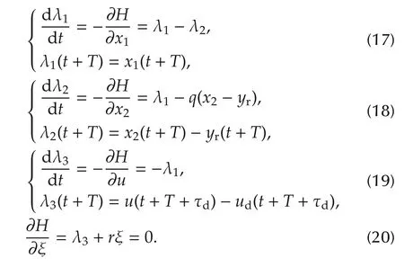
From(20),it is found that ξ is easily solved by λ3which is obtained by the backward calculation of(17)–(19).For nonlinear systems,it is not easy to obtain the solution generally although fast algorithms have been proposed for example C/GMRES[9].
For the implementation of the designed MPC, the augmented systems(14)and(17)–(19)are discretized as represented by
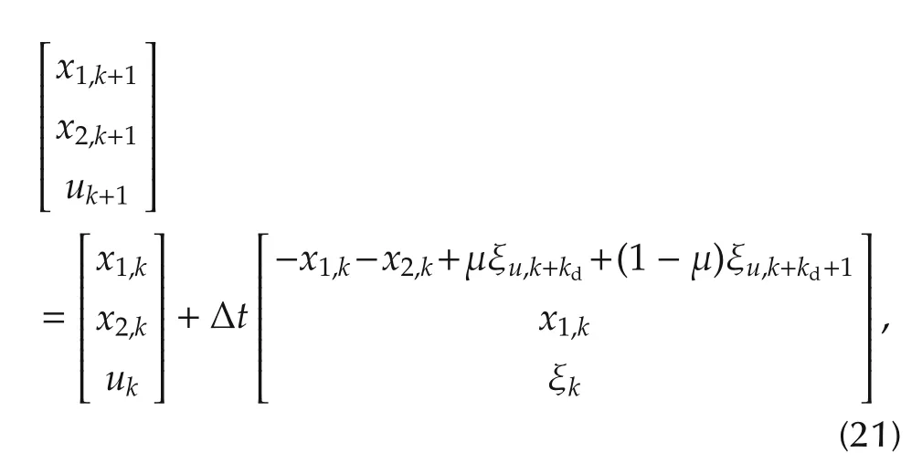
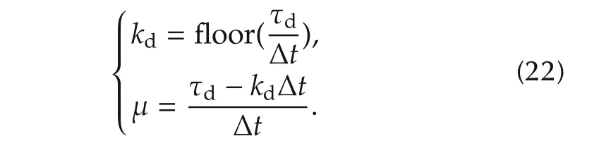
where the initial condition is the states of the augmented system at k=0.k corresponds to τ=t+kΔt,and μ is represented by
For the backward calculation,
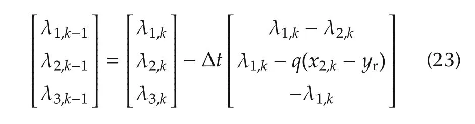
is given,where the terminal conditions is given according to(23).From(20),ξkis obtained as
Hence,ukis obtained by

The best effort of the simulation results by the algorithm is shown in Fig.13.The comparison of Fig.13 and Fig.12 indicates that the generalized engine control gave the better performance than the designed MPC described above.Unfortunately,y does not follow the reference accurately and an offset appears between y and yr.The analysis of the issue tells us that the offset does not appear only when the nominal model is controlled by the algorithm.
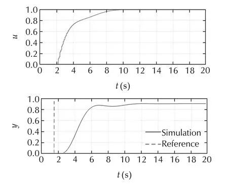
Fig.13 Control result of ordinaly MPC.
To resolve the issue,the new variables ofare introduced.Under the assumptionThe Smith-Davison type[10]augmente d system is introduced by
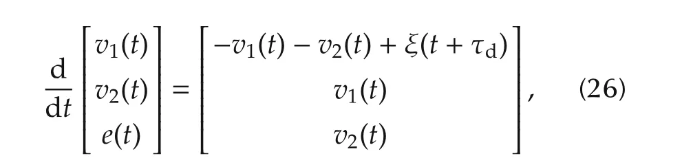
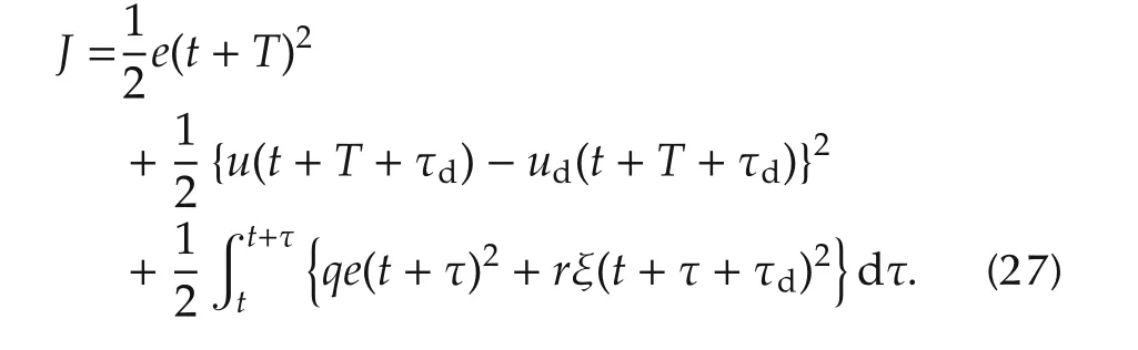
The MPC is derived from(27)according to the optimal condition similar to the equations from(16)to(20).
The drived MPC needs υ1and υ2.Thus,they are approximated by
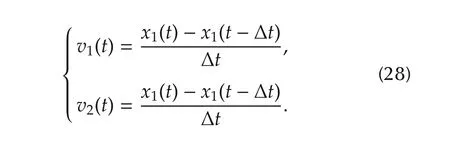
Fig.14 shows a simulation result of the MPC derived by the criterion(27).It is found that the offset disappears in Fig.14 although the algorithm becomes a little bit complex.However,the comparison of Fig.12 and Fig.14 indicates that the generalized engine control still gives a better performance than the MPC.The reason is that the generalized engine control is TDFC which has a strong feedforward but the MPC does not have such the control structure.
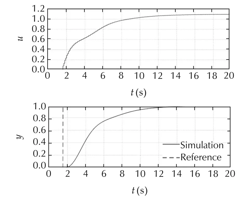
Fig.14 Control result derived from augmented system.
It is possible that the MPC can be applied to P of the generalized engine control shown in Fig.10.Fig.15 shows a control result of the idea.The response shown in Fig.15 is highly improved but the comparison of Fig.12 and Fig.15 shows that both performances are almost the same.
The investigation in this section indicates that careful considerations of criterion and augmented system are necessary when MPC is applied.Especially,mappings between the control purpose,the closed-loop behavior,and the criterion have to be sufficiently grasped.It can need a lot of disciplines.
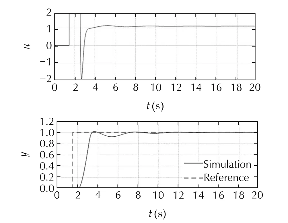
Fig.15 Control result of the generalized control.
5 Conclusions
It has been expected that MPC is a systematic and flexible control to satisfy the requirements from engine controls.To clarify advantages obtained by MPC,the base control must be defined to be compared with MPC.For the purpose,a tracking control was abstracted from existing engine controls and generalized.The generalized engine control is a two degree of freedom control derived from Smith’s time delay compensator which has the similar control structure of disturbance observer control including an internal model control(IMC).It was further transformed so that various controls are easily applied.
Two types of MPC were designed in this paper.One is the ordinary MPC which derived from the criterion including the derivative of the input and the other is derived by Smith-Davison type control design.The former one caused an offset between the output and the reference.On the other hand,the latter one removed the offset.The comparison with the generalized engine control showed that it is better than both MPCs which make the output follow the reference by the integration of control error although the generalized engine control has the strong feedforward.
The MPC derived from Smith-Davison type control design was put into the feedback portion of generalized engine control.The tracking capability was highly improved but the output behavior is almost same as the generalized engine control with PID control.It indicates that the generalized control structure practically provides an excellent control framework.
[1]S.D.Cairano,D.Yanakiev,A.Bemporad,et al.Model predictive powertrain control:an application to idle speed regulation.Automotive Model Predictive Control.Berlin Heidelberg:Springer,2010:183–194.
[2]A.Kamik,D.Pachner,A.M.Fuxman,et al.Model Predictive Control for Engine Powertrain Thermal Management Applications.SAE Technical paper 2015-01-0336.Detroit:SAE International,2015.
[3]L.He,T.Shen,L.Yu,et al.A model-predictive control-based torque demand control approach for parallel hybrid powertrains.IEEE Transactions on Vehicular Technology,2013,62(3):1041–1052.
[4]A.Lagerberg,B.Egardt.Model predictive control of automotive powertrains with backlash.IFAC Proceedings Volumes,2005,38(1):1–6.
[5]D.E.Rivera,M.Morari,S.Skogestad.Internal model control:PID controller design.Industrial and Engineering Chemistry Process Design and Development,1986,25(1):252–265.
[6]T.N.Hein,O.Kaneko,S.Yamamoto.Fictitious reference iterative tuning of internal model controllers for non-minimum phase systems:A Laguerre expansion approach.SICE Journal ofControl,and System Integration,2013,6(1):38–44.
[7]K.Ohnishi,M.Shibata,T.Murakami.Motion control for advanced mechatronics.IEEE/ASME Transactions on Mechatronics,1996,1(1):56–67.
[8]A.Ohata.Automotive engine control with rational function satisfying inequality constraint.IFAC-PapersOnLine,2016,49(11):673–678.
[9]T.Ohtsuka,H.A.Fujii.Real-time optimization algorithm for nonlinear receding-horizon control.Automatica,1997,33(6):1147–1154.
[10]E.J.Davison,H.W.Smith.Pole assignment in linear time-invariant multivariable systems with constant disturbances.Automatica,1971,7(4):489–498.
3 January 2017;revised 11 February 2017;accepted 13 February 2017
DOI10.1007/s11768-017-7002-4
.
E-mail:akira_ohata_za@mail.toyota.co.jp.Tel:+81-55-977-7547;fax:+81-55-997-7873.
©2017 South China University of Technology,Academy of Mathematics and Systems Science,CAS,and Springer-Verlag Berlin Heidelberg
Akira OHATAgraduated from Tokyo Institute of Technology in 1973,and directly joined Toyota Motor Corporation.He was involved in exhaust gas emission control,variable intake system,HEV control,vehicle controls,model-based development(MBD),and the education of advanced control theory at Toyota.He had the standardization activity of software dependability assurance of consumer devices in Object Management Group(OMG).He was a senior general manager of Toyota Motor Corporation,a research fellow of Information Technology Agency(IPA)under the Ministry of Economy,Trade,and Industry.He retired from Toyota and joined TECHNOVA as a senior adviser.He received the most outstanding paper award in convergence 2004,technical contribution award from JSAE in 2009,and others in 2012,2015,and 2016.E-mail:akira_ohata_za@mail.toyota.co.jp.
 Control Theory and Technology2017年2期
- Control Theory and Technology的其它文章
- Towards to dynamic optimal control for large-scale distributed systems
- MPC-based torque control of permanent magnet synchronous motor for electric vehicles via switching optimization
- Online calibration of combustion phase in a diesel engine
- Optimal heat release shaping in a reactivity controlled compression ignition(RCCI)engine
- Two-degree-of-freedom H-infinity control of combustion in diesel engine using a discrete dynamics model
- Experimental investigation of control updating period monitoring in industrial PLC-based fast MPC:Application to the constrained control of a cryogenic refrigerator