
Two-degree-of-freedom H-infinity control of combustion in diesel engine using a discrete dynamics model
2017-12-26 09:28:34MitsuoHIRATASotaISHIZUKIMasasyasuSUZUKI
Control Theory and Technology 2017年2期
Mitsuo HIRATA,Sota ISHIZUKI,Masasyasu SUZUKI
Department of Electrical and Electronic Systems Engineering,Utsunomiya University,7-1-2 Yoto,Utsunomiya,Tochigi 321-8585,Japan
Two-degree-of-freedom H-infinity control of combustion in diesel engine using a discrete dynamics model
Mitsuo HIRATA†,Sota ISHIZUKI,Masasyasu SUZUKI
Department of Electrical and Electronic Systems Engineering,Utsunomiya University,7-1-2 Yoto,Utsunomiya,Tochigi 321-8585,Japan
This paper proposes an H-infinity combustion control method for diesel engines.The plant model is the discrete dynamics model developed by Yasuda et al.,which is implementable on a real engine control unit.We introduce a two-degree-of-freedom control scheme with a feedback controller and a feedforward controller.This scheme achieves both good feedback properties,such as disturbance suppression and robust stability,and a good transient response.The feedforward controller is designed by taking the inverse of the static plant model,and the feedback controller is designed by the H-infinity control method,which reduces the effect of the trubocharger lag. The effectiveness of the proposed method is evaluated in simulations using the nonlinear discrete dynamics model.
Combustion control,diesel engines,H-infinity control,two-degree-of-freedom control
1 Introduction
In diesel engines,efforts to reduce both NOxand particulate matter(PM)emissions have increased in recent years due to the need to comply with increasingly stringent emission regulations.To meet these requirements,new technologies such as exhaust gas recirculation(EGR)circuits,variable-geometry turbochargers(VGTs),and exhaust gas after treatment systems have been introduced[1–3].However,these technologies increase the complexity of the system architecture and the difficulty of the control system design.
Conventional controllers are based on lookup tables compiled from the results of many experiments[4].The complexity of recent engines has greatly increased the effort of constructing these tables.Premixed charge compression ignition(PCCI)combustion is the inevitable next step,as it achieves high energy efficiency while reducing the engine-out emissions,but it is nonrobust and difficult to control[5–8].Indeed,PCCI combustion cannot be adequately controlled by conventional control,in either steady-state or transient operation.Model-based controller design methods offer a promising alternative to traditional control of PCCI[9,10].
This paper proposes an H∞combustion control method for diesel engines.The plant model is the discrete dynamics model,which has been developed by Yasuda et al.as a future implementable model on a real engine control unit as a feedforward controller to predict control input from reference inputs and multiple sensory information without optional lookup tables[11,12].We introduce a two-degree-of-freedom control scheme with a feedback controller and a feedforward controller.This scheme achieves both good feedback properties,such as disturbance suppression and robust stability,and a good transient response.The feedforward controller is designed by taking the inverse of the static plant model,and the feedback controller is designed by the H∞control method[13].The generalized plant for the H∞controller design is constructed to reduce not only various disturbances but also the influence of the turbocharger lag.
The effectiveness of the proposed method is evaluated in simulations using the nonlinear discrete dynamics model.
2 Discrete dynamics model
To reduce the computational cost,the discrete dynamics model calculates fundamental thermodynamic equations and some empirical equations only at representative points in the engine cycle;namely,the timings of the exhaust valve closing(EVC),the intake valve closing(IVC),the ignition(IGN),the peak pressure(PEAK),and the exhaust valve opening(EVO).
Initially,the discrete dynamics model comprised a single injection system[11];then,the model was extended to include multi-injection systems[12].In this initial examination,we assume the single injection system.The state variable Xk,the input Uk,and the output Ykof the single-injection model are presented in Table 1.In terms of these variables,the discrete dynamics model with single injection is expressed as1The EGR ratio is also the input to the discrete dynamics model.However,in this study,we treat the EGR ratio as a constant(30%)rather than as an input variable.:
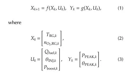
In(1),f and g are complex nonlinear equations,and the details are described in[11].

Table 1 Definitions of states,inputs,and outputs in the discrete dynamics model.
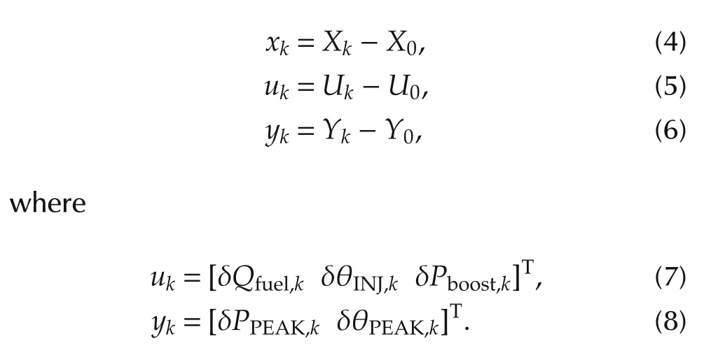
In the controller design,(1)is linearized around the equilibrium points U0,Y0,and X0of the input,output,and state,respectively.The deviations from the equilibrium points are defined as follows:
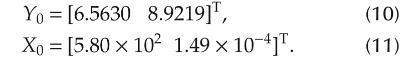
In this article,the equilibrium point U0of the input is selected as

Thus,Y0and X0are obtained as
Based on these equilibrium points,we obtained a linearized model with the following state-space representation:
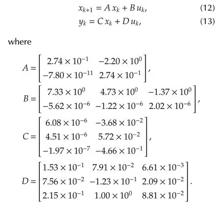
We also define the transfer function P:

3 Structure of control system
We introduce the following assumptions to design the two-degree-of freedom control system.
a)The peak pressure δPPEAK,kand the peak pressure timing δθPEAK,kcan be measured at time k+1 by sensors embedded in the cylinder.
b)The actual boost pressure δPboost,kfollows the referencewith a first-order lag,i.e.,the following equation holds:
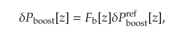
where δPboost[z]andare the z-transforms of δPboost,kandrespectively,and Fb[z]is a discrete-time first-order lag filter with a time constant of Tb=2s.
c)The boost pressure δPboost,kcan be measured without a time delay.
d)The feedback controller can manipulate the fuel injection timing δθINJ,kand the boost pressure reference
By assumption a),the measurement output ys,kis given by

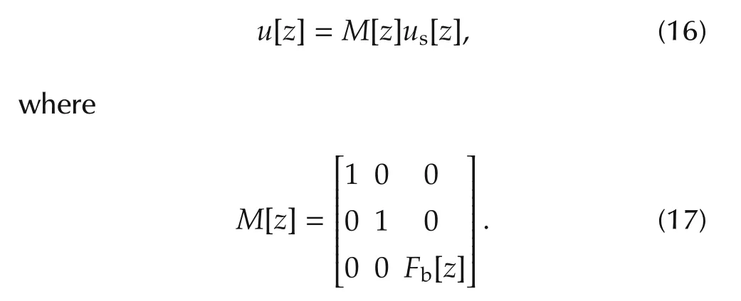
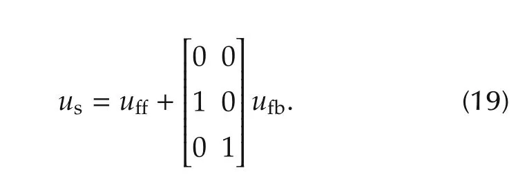
Further,by assumption b),the input u of P is related to the controller output usas
Under the above assumptions,a two-degree-offreedom control system was proposed as shown in Fig.1.The reference input r is assumed to be
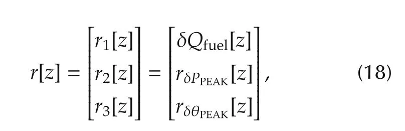
where r1[z]is the actual fuel injection quantity δQfuelgiven by a driver,and r2[z]and r3[z]are the references for δPPEAK,and δθPEAK,respectively.As shown in the next section,δQfuelis included in the reference r since it is used to calculate the second and the third elements of the feedforward input uあ.
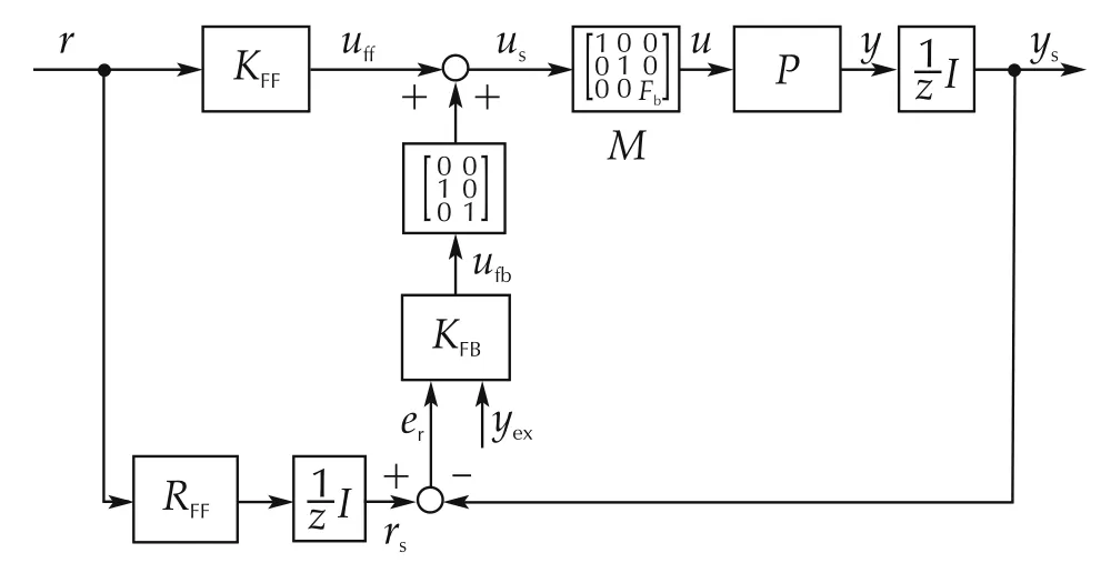
Fig.1 Proposed control system.
The reference input rsis the reference to ys,and it is generated by RFF.An one sampling delay z−1is introduced to generate rsbecause yshas the same delay relative to y.The feedforward input uあis generated by the feedforward controller KFF.
The inputs of the feedback controller KFBare the error er=rs−ysand the external input yex,which is introduced to compensate for the turbocharger lag,and the controller output is ufb.From assumption d),we have
The design method of KFF,RFF,and KFBwill be shown in the next section.
4 Design of KFFand RFF
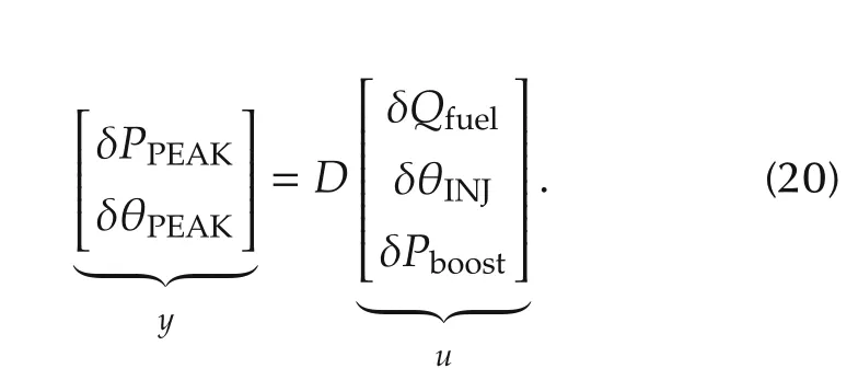
By examining the linearlized model(12)and(13),we found that the dynamics of the plant exert a small effect.Thus,for the feedforward controller design,we assume that the input and output relation can be described by the direct transmission term D as follows:
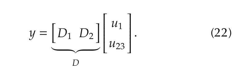
We define u1and u23as
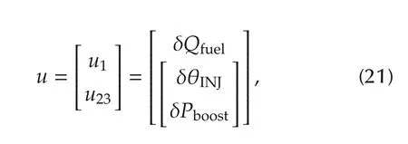
then(20)can be described as
The feedforward controller KFFwhich generates the following feedforward input,
should be designed so as to satisfy the following relation for a given reference input r,
By isolating u23in(22)and using(24),we have
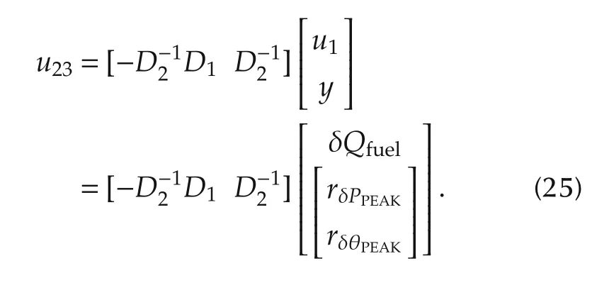
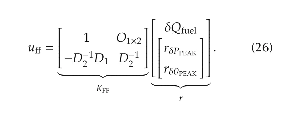
Therefore we have the following feedforward controller KFFfrom(23)and(25):
On the other hand,RFFis defined to generate the reference to δPPEAKand δθPEAKas follows:

In order to evaluate the performance of the feedforward controller KFF,we obtained the output response by substituting the output of(26)into(1).The reference for fuel injection quantity was increased 5mm3from the equivalent point at t=1.The references for peak pressure and peak pressure timing were increased by 1 unit from the equivalent points as step signal at t=4 and t=7,respectively.Fig.2 shows the simulation result,and it indicates that the feedforward controller works correctly.
Further,in order to evaluate the influence of the turbocharger lag,M of(17)was inserted between the output of(26)and(1),and the simulation was conducted again.As shown in Fig.3,the tracking performance was degraded and it shows that the turbocharger lag cannot be neglected.
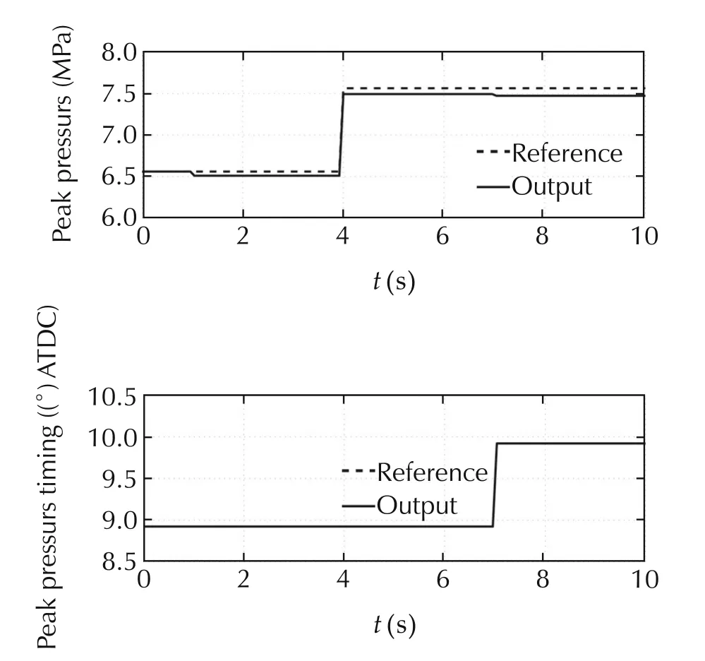
Fig.2 Simulation result 1.
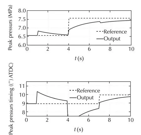
Fig.3 Simulation result 2.
5 Design of H∞controller
5.1 H∞control theory
Given a generalized closed-loop configuration shown in Fig.4,the H∞control is formulated as a problem that finds an internally stabilizing controller that minimizes the H∞norm from w to z[13].The transfer matrix G in Fig.4 is referred to as a generalized plant.
The H∞controller minimizes H∞norm,which corresponds to the maximum gain of the transfer function.Therefore,the H∞control is essentially a disturbance suppression.Multiple disturbances are imposed to the controlled object in actual systems,and the modeling error can also be regarded as an equivalent disturbance[14].Therefore,the H∞control is a powerful approach because various control problems are reduced to disturbance attenuation problems.
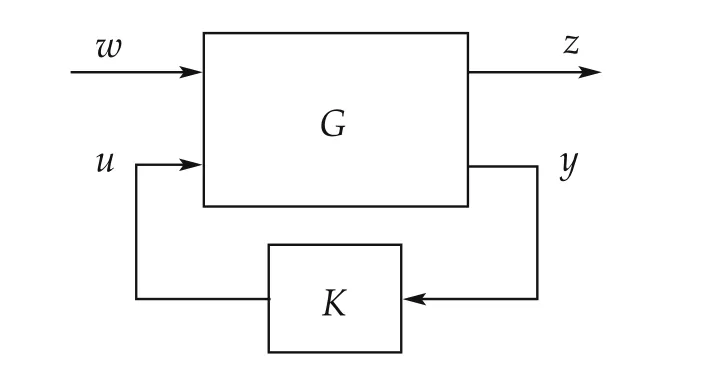
Fig.4 Standard configuration for H∞control.
5.2 H∞controller design
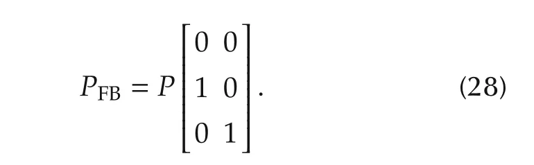
The H∞controller KFBin Fig.1 is designed so as to reduce the influence of the turbocharger lag.By assumption d),the plant PFBfor the H∞controller design is defined as
The generalized plant for the H∞controller design is shown in Fig.5.MFBis introduced to incorporate the turbocharger lag into controller design as follows:

wdand wnrepresent the disturbance and the measurement noise,respectively.zuand zeare the controlled outputs that are minimized by the H∞controller.
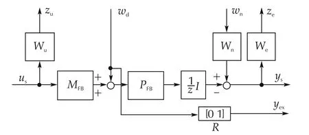
Fig.5 Generalized plant.
The second element wd2of wdis the equivalent disturbance that represents the turbocharger lag,and let us estimate the amount of the equivalent disturbance.
Since the feedforward controller was designed by taking the inverse of D,it is desirable to add a feedforward inputuあbetween Mand P in the two-degree-of-freedomcontrol system(Fig.1).However,the actual boost pressure cannot be directly manipulated,so uあis added to the input side of M,as shown in Fig.1.
Fig.6(a)presents the extracted block diagram of the input and output portions of Fbin Fig.1.Fig.6(a)is transformed to Fig.6(b)by preserving the transfer function from uあ3to u32uあ3and u3represent the 3rd element of uあ and u,respectively.The same manner will be used..
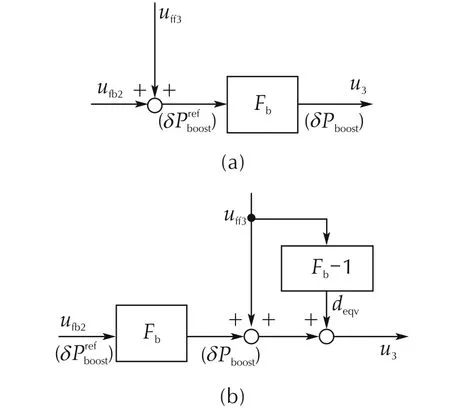
Fig.6 Equivalent transformation of uあ3.

From this diagram,we observe that adding uあ3to the input side of Fbis equivalent to adding to the output side of Fb.Since deqvcan be calculated from(26)and(30),it is reasonable to assume that deqvis a measurable signal.In the generalized plant Fig.5,wd2corresponds to deqv,and it is defined as a measured signal yex.
The weighting functions We,Wu,and Wnwere selected with some trial and errors as
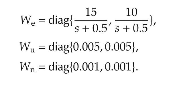
All of the weighting functions were discretized by a pole-zero matching equivalent method.Next,referring to discrete-time H∞control theory,we calculated an H∞controller with these weighting functions using the MATLAB robust control toolbox R2012a.The achieved minimum H∞norm from w to z was 0.81.The singular values plot of the H∞controller is shown in Fig.7,and the state space matrices of the obtained H∞controller are shown below
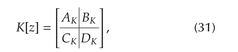
where
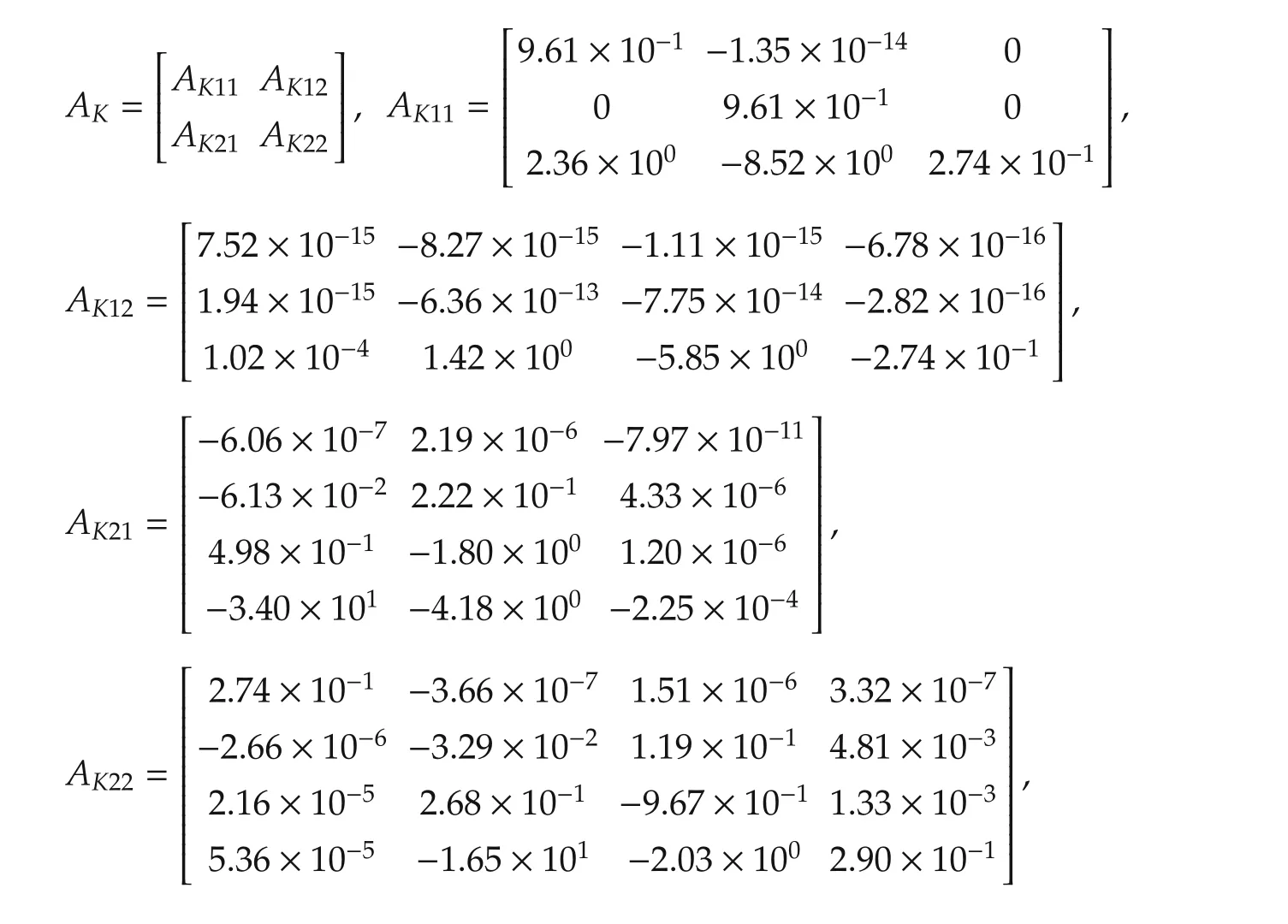
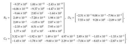
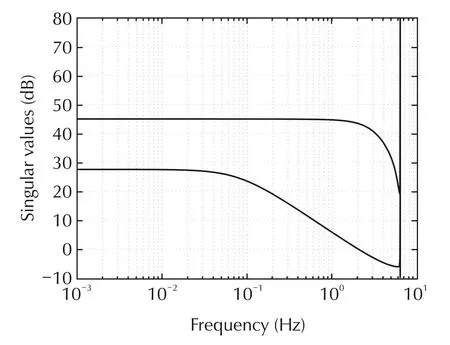
Fig.7 Singular values plot of H∞controller.
5.3 Simulation
The obtained H∞controller was employed as the feedback controller of the two-degree-of-freedom control system in Fig.1,and evaluated in simulations.The linear model P was replaced by the nonlinear discrete dynamics model(1)for simulation.The second input yexof the H∞controller was given as
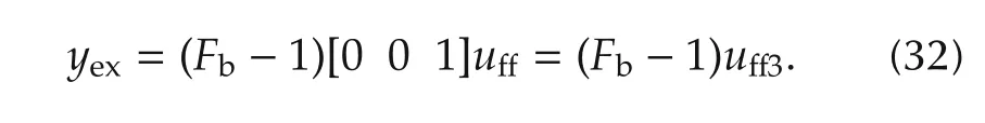
Fig.8 shows the simulation result.The references are same as that used to evaluate the performance of the feedforward controller.From Fig.8,a small interference between channels are observed,though,the output of each channel accurately follows the reference input.
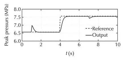
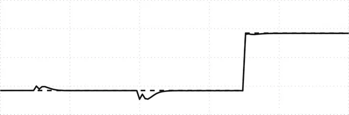
Fig.8 Simulation result 3.
Fig.9shows the responses of the control inputs. In the graph of Pboost,us3is the reference of the boost pressure,and u3is the actual boost pressure.The reference of the boost pressure moves largely to compensate for the turbocharger lag.
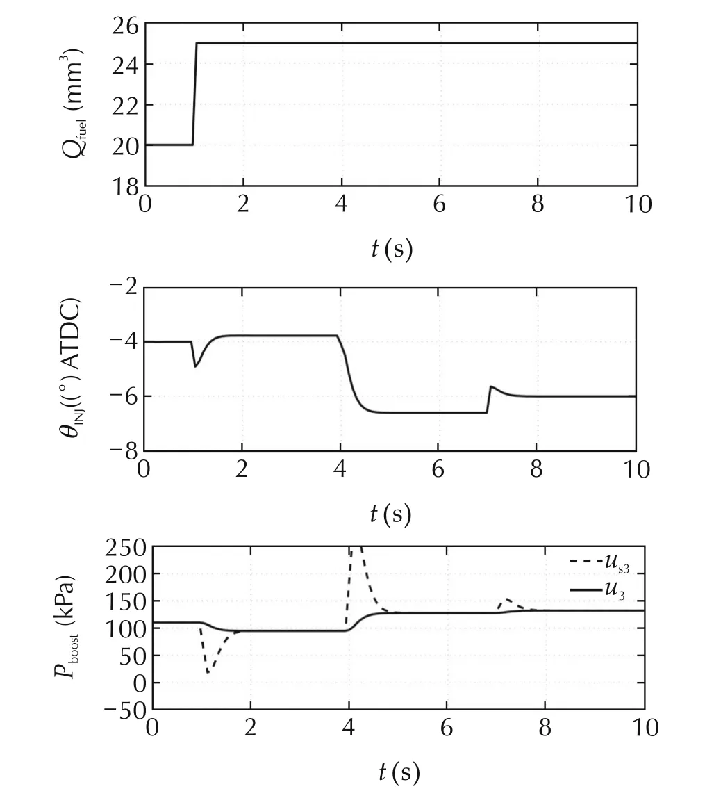
Fig.9 Simulation result 3(control input).
6 Conclusions
In this study,we proposed a two-degree-of-freedom control structure for a combustion control.The feedforward controller was designed using the static model of the plant.On the other hand,the feedback controller was designed by the H∞control theory.The H∞controller was obtained by accounting for the turbocharger lag.The improved tracking performance was demonstrated in simulation.
Future work will focus on the implementation of the proposed method into real engine.Concerning the fixed EGR ratio,it should be treated as a variable because it varies in actual driving situation. As for the input and output of the plant,they might deviate from the equivalent point significantly and the plant exhibits a nonlinearity.In this case,a gain scheduled H∞control approach will be effective to cope with the nonlinearity[15].It is also effective to replace the gain feedforward controller KFFby a nonlinear feedforward controller obtained by taking the inverse of the discrete dynamics model,though,we must wait for the improvement of current ECU’s computation performance.
[1]H.Xie,S.Li,K.Song,et al.Model-based decoupling control of VGT and EGR with active disturbance rejection in diesel engines.IFAC Proceedings Volumes,2013,46(21):282–288.
[2]A.G.Stefanopoulou,I.Kolmanovsky,J.S.Freudenberg.Control of variable geometry turbocharged diesel engines for reduced emissions.IEEE Transactions on Control Systems Technology,2000,8(4):733–745.
[3]G.H.Abd-Alla.Using exhaust gas recirculation in internal combustion engines:a review.Energy Conversion and Management,2002,43(8):1027–1042.
[4]D.Schiefer,D.Maennel,W.Nardoni.Advantages of Diesel Engine Control Using In-Cylinder Pressure Information for Closed Loop Control.SAE Technical Paper 2003-01-0364.Detroit:SAE International,2003.
[5]G.D.Neely,S.Sasaki,Y.Huang,et al.New Diesel Emisson Control Strategy to Meet US Tier 2 Emissions Regulations.SAE Technical Paper 2005-01-1091.Detroit:SAE International,2005.
[6]A.M.Kulkarni,K.C.Stricker,A.Blum,et al.PCCI Control Authority of a Modern Diesel Engine Outfitted With Flexible Intake Valve Actuation.SAE Technical Paper 2009-01-18882.Detroit:SAE International,2009.
[7]A.E.Ctania,S.d’Ambrosio,R.Finesso,et al.Combustion system optimization of a low compression-ratio PCCI diesel engine for light-duty application.SAE International Journal of Engines,2009,2(1):1314–1326.
[8]T.Ishikawa,N.Horibe.Characteristics and problems of diesel base PCCI combustion.Marine Engineering,47(6):859–864(in Japanese).
[9]L.Guzzella,C.H.Onder.Introduction to Modeling and Control of Internal Combustion Engine Systems.Berlin:Springer,2010.
[10]M.Iwadare,M.Ueno,Y.Hattori,et al.Modeling and control systems design by model predictive control for air-path system of diesel engine.Transactions of the Society of Instrument and Control Engineers,2010,46(8):456–462(in Japanese).
[11]K. Yasuda, Y. Yamasaki, S. Kaneko, et al. Diesel combustion model for on-board application. International Journal of Engine Research,2016,17(7):748–765.
[12]H.Shimizu,K.Hoshida,Y.Nakamura,et al.Discrete dynamics model for diesel combustion:expansion of the model to multiinjection(two-stage injection).2nd report.Proceedings of the 25th Internal Combustion Engine Symposium.Tokyo,2014(in Japanese).
[13]K.Zhou,J.C.Doyle.Essentials of Robust Control.Englewood Cliffs:Prentice Hall,1998.
[14]T.Yamaguchi,M.Hirata,C.K.Pang.High-Speed Precision Motion Control.New York:CRC Press,2012.
[15]P.Apkarian,P.Gahinet,G.Backer.Self-scheduled H∞control of linear parameter-varying system–a design example.Automatica,1998,31(9):1251–1261.
28 September 2016;revised 2 March 2017;accepted 3 March 2017
DOI10.1007/s11768-017-6144-8
†Corresponding author.
E-mail:hirata@cc.utsunomiya-u.ac.jp.
This work was supported by “Innovative Combustion Technology”of a cross-ministerial strategic innovation promotion program(SIP)under Japan Science and Technology Agency(JST).
©2017 South China University of Technology,Academy of Mathematics and Systems Science,CAS,and Springer-Verlag Berlin Heidelberg
Mitsuo HIRATAreceived B.E.,M.E.,and Ph.D.degrees from Chiba University in 1991,1993,and 1996,respectively.From 1996 through 2004,he was a Research Associate in the Department of Electronics and Mechanical Engineering,Chiba University.From 2002 through 2003,he was a Visiting Scholar in the Department of Mechanical Engineering,University of California,Berkeley.Since June 2004,he has been at Utsunomiya University,where he is currently a Professor of the Department of Electrical and Electronic Systems Engineering.His research interests include robust control,high-precision motion control,sampled-data control,and their applications to industrial systems.He is a member of IEEE,SICE,ISCIE,IEEJ,and JSME.E-mail:hirata@cc.utsunomiya-u.ac.jp.

Sota ISHIZUKIreceived the B.E.and M.E.degrees from National Institute of Technology,Nagaoka College and Utsunomiya University in 2015 and 2017,respectively.His current research interest is advanced control of combustion in diesel engines.

Masayasu SUZUKIreceived the B.E.,M.E.,and Ph.D. degrees in Aerospace Engineering from Nagoya University,Nagoya,Japan,in 2005,2007,and 2010,respectively.From 2010 to 2013,he was a Post-Doctoral researcher of FIRST Aihara Innovative Mathematical Modelling Project,Japan Science and Technology Agency,in the Department of Mechanical and Environmental Informatics,Tokyo Institute of Technology.Since December 2013,he has been with the Department of Electrical and Electronic Systems Engineering,Utsunomiya University,where he is currently an Assistant Professor.His research interests include control of nonlinear systems,control of distributed parameter systems,and network structure identification.He is a member of IEEE,SICE,ISCIE,IEEJ,JSME and IEICE.E-mail:ma-suzuki@cc.utsunomiya-u.ac.jp.
 Control Theory and Technology2017年2期
- Control Theory and Technology的其它文章
- Towards to dynamic optimal control for large-scale distributed systems
- Comparison of generalized engine control and MPC based on maximum principle
- MPC-based torque control of permanent magnet synchronous motor for electric vehicles via switching optimization
- Online calibration of combustion phase in a diesel engine
- Optimal heat release shaping in a reactivity controlled compression ignition(RCCI)engine
- Experimental investigation of control updating period monitoring in industrial PLC-based fast MPC:Application to the constrained control of a cryogenic refrigerator