
MPC-based torque control of permanent magnet synchronous motor for electric vehicles via switching optimization
2017-12-26 09:28:42BingtaoRENHongCHENHaiyanZHAOWeiXU
Control Theory and Technology 2017年2期
Bingtao REN,Hong CHEN†,Haiyan ZHAO,Wei XU
1.State Key Laboratory of Automotive Simulation and Control,Jilin University,Changchun Jilin 130025,China;
2.Department of Control Science and Engineering,Jilin University,Changchun Jilin 130025,China
MPC-based torque control of permanent magnet synchronous motor for electric vehicles via switching optimization
Bingtao REN1,2,Hong CHEN1,2†,Haiyan ZHAO1,2,Wei XU2
1.State Key Laboratory of Automotive Simulation and Control,Jilin University,Changchun Jilin 130025,China;
2.Department of Control Science and Engineering,Jilin University,Changchun Jilin 130025,China
In order to effectively achieve torque demand in electric vehicles(EVs),this paper presents a torque control strategy based on model predictive control(MPC)for permanent magnet synchronous motor(PMSM)driven by a two-level three-phase inverter.A centralized control strategy is established in the MPC framework to track the torque demand and reduce energy loss,by directly optimizing the switch states of inverter.To fast determine the optimal control sequence in predictive process,a searching tree is built to look for optimal inputs by dynamic programming(DP)algorithm on the basis of the principle of optimality.Then we design a pruning method to check the candidate inputs that can enter the next predictive loop in order to decrease the computational burden of evaluation of input sequences.Finally,the simulation results on different conditions indicate that the proposed strategy can achieve a tradeoff between control performance and computational efficiency.
Permanent magnet synchronous motor,electric vehicle,torque optimal control,model predictive control
1 Introduction
As an effective means to reduce pollution,electric vehicles(EVs)have drawn many attentions in the past few decades[1].Electric machines are the key component of EV technologies,which have to offer high efficiency,high controllability and wide-speed range.Due to high power density, high reliability and relatively smooth running,permanent magnet synchronous motor(PMSM)is popularly used for EVs as the motor type and has been actively developed by many research institutes[2–4].In order to effectively achieve drive demand of vehicle control system,the PMSM torque control plays a very important role in the EV technologies.
To ensure fast and smooth torque response and high dynamic performance,many PMSM control methods have been studied in literatures.Field orientation control(FOC)and direct torque control(DTC)are two kinds of classical control schemes well used in alternating current(AC)motor system[5].It is difficult to handle multiple requirements and existing current constraints.In recent years,a novel control scheme via switching optimization has been studied[6–8],whose common idea is to directly manipulate the switch signals of inverter to control current or torque based on the predictive information of the system’s future behavior.The modulator is not required and the control pulse for inverter is a variable frequency signal.As an effective way to deal with a constrained optimal control problem,model predictive control(MPC)is chosen via switching optimization to satisfy diverse and even conflicting requirements in PMSM control system[9–11].It not only can produce instantaneous currents with high accuracy in a transient interval,but also reduce the switching losses by switching optimization which represent a major part of the energy losses of overall drive system.
Due to the discrete switch states of modern power inverter,this MPC-based switching optimization scheme has to select the control input in a finite set of discrete values[6,12].By investigating all candidate sequences,the full enumeration method is a simple method to fast find the optimal switch sequence[13–15].But this method is only available for the MPC optimization scheme with one or two predictive horizons.The long predictive horizon greatly boosts the performance of MPC optimization,in the sense that the switching losses and the current or torque tracking error are further lower than that with short horizon.Meanwhile,as the increasing of predictive horizon,the number of candidate sequences may become very large and the computational burden will be heavy,full enumeration is not suitable for the case with long horizon. This switching combinational optimization in PMSM control system is a challenging problem that has led many researchers to study some efficient solution approaches.Reference[16]presents a control Lyapunov function to dynamically prune suboptimal sequences of search space to decrease the computational burden of MPC scheme.In[17],a predictive control technique with the predefined constraints is proposed to reduce the number of the available switch states of the voltage source inverter.Reference[18]adopts a branch and bound technique to achieve computationally efficient predictive direct torque control.These methods only explore some pruning methods and have not made a definite searching process to reduce some unnecessary computation and achieve a tradeoff between control performance and computation speed.
To achieve fast and smooth torque demand of vehicle,this paper investigates a torque control strategy via switching optimization for PMSM system based on model predictive control.With respect to other methods considered in this presentation,the main merits of the proposed scheme cover the following points:1)The control scheme regards the motor and inverter as a complete controlled system,and directly optimizes the switch states of inverter.2)The MPC-based control strategy can simultaneously meet multiple requirements of EV propulsion,i.e.,to achieve fast and smooth torque demand,to reduce energy consumption and to deal with current saturation constraint.This leads to energy saving in a wide operating range and efficiency improvement while benefiting from the switching optimization advantages.3)Considering that dynamic programming(DP)[19]is avaiable for the solution to discrete-time sequential decision process,we use it to build a searching tree to look for optimal inputs in each stage on the basis of optimality principle.Then,to decrease the computational burden of evaluation of input sequences,a pruning method is designed to check candidate branches of this searching tree whether to enter the next predictive loop.The results in simulation demonstrate that it can effectively achieve torque control.
The organization of this paper is as follows.In Section 2 a control oriented nonlinear model of the inverter and PMSM system is built.Section 3 introduces an MPC approach based on dynamic programming with branch and bound for motor torque control.Section 4 gives the simulation results to validate the effectiveness of the proposed strategy for different cases.Finally the conclusion and future work are summarized in Section 5.
2 Modelling for control design
The PMSM is driven by a two-level three-phase voltage source inverter from DC voltage source.They can be regarded as a complete controlled system,whose structure diagram is shown in Fig.1.To implement the torque control for PMSM system,an adequate system model is essential.
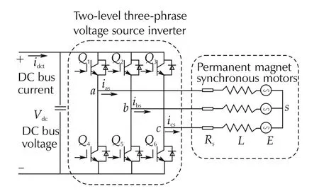
Fig.1 Structure diagram of the PMSM system.
2.1 Three phase inverter
The three-phase inverter connects the three phases of motor to the DC positive or negative end and is composed by six power devices,like insulated-gate bipolar transistors(IGBT)that combines high efficiency and fast switching[20].
The model of power device is considered as an ideal switch with only two states:on and off in[6].In order to avoid short circuiting connections,two switches in each inverter bridge in Fig.1 cannot operate at the same time.We define switching signal for each inverter bridge as Sa,b,cwith only two states 1 and 0:
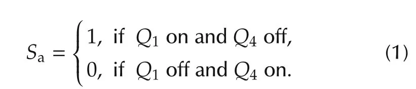
Sband Schave the same definition,and S=[SaSbSc]Tis defined as switching vector of inverter.Therefore,the total number of switch states of the inverter is equal to the number of different combinations of the two switch states of each switch,which has eight possible switch states with S∈{S0,S1,...,S7}described as Fig.2.The output voltage in each bridge is defined as

where Vdcdenotes DC power supply voltage.
Considering an unitary vectorwhich represents the phase displacement between two phases,to preserve the amplitude of phase voltage unchanged,the output voltage vector Vscan be defined as

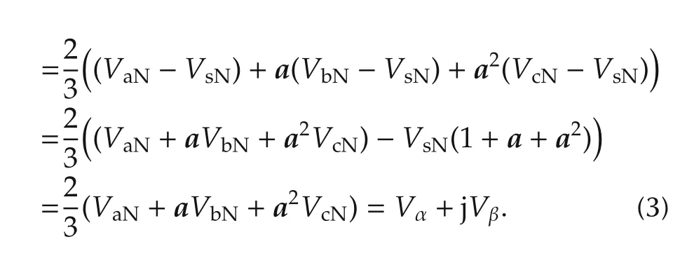
By substituting vector a into(3),the output voltage is expressed as a matrix form[VαVβ]Tin the α-β axis:
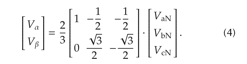
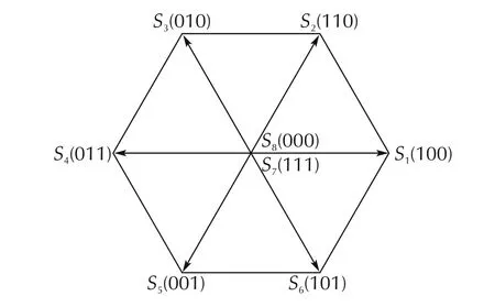
Fig.2 Switch states.
Frequent switching action can also cause some loss,hence inverter loss needs to be modeled here, consisting of switching loss and conduction loss.
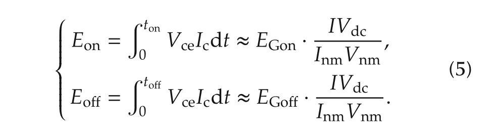
IGBT switching loss(turn-on and turn-off):
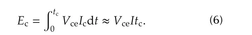
IGBT conduction loss:
Energy loss of one phase IGBT-bridge during one sample time:
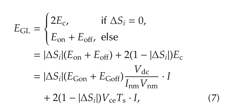
where EGon,EGoあdenote switching energy loss of turnon and turn-off of IGBT,Vnm,Inmare nominal voltage and current,and Vcedenotes gate threshold voltage.
2.2 PMSM motor
By the Park transformation,the stator voltage Vr=Vd+jVqin the rotor coordinate can be derived from the stator coordinate with Vr=Vse−jθe,which is expressed as a matrix form:
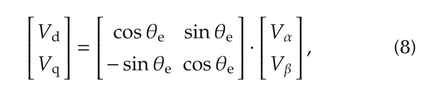
where θeis electrical angle of the rotor.
Based on Kirchoff’s voltage law and Newton’s second law,the current dynamics can be derived from equation(9)in the rotor direct and quadrature(d-q)coordinate.
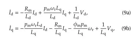
where Idand Iqdenote d and q axis stator currents respectively,Vdand Vqdenote d and q axis stator voltages,Ldand Lqdenote d and q axis inductances,ωrdenotes rotor shaft mechanical speed,Rmdenotes resistance of the stator windings,pmdenotes number of magnetic pole pairs of motor,φmdenotes the amplitude of the flux induced by the permanent magnets of the rotor in the stator phases.
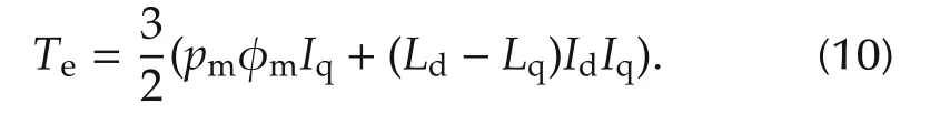
The electromagnetic torque Tein the machine depends on the flux magnitude φmand the stator current vectors Idand Iq,as follows:
2.3 State space equation of the complete system
We choose stator currents as system states with x=[IdIq]T,rotor speed as time varying parameter with d=ωrand switch inputs as control inputs with u=[SaSbSc]T.Hence,this is a special hybrid system with continuous states and discrete control inputs.Based on the related equations above(2),(4),(8)and(9),the space state model of the complete PMSM system can be developed:
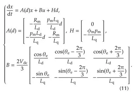

where Tsis afixed step size,is a sample time and t denotes running time.
For performing a torque control design in real-time system,the system equation must be rewritten as a discrete-time equation used for calculation of the predictive output.Based on the forward Euler method,a discrete-time system model is obtained as
3 Torque control design based on model predictive control
In this section,we will design an MPC strategy via switching optimization to realize PMSM torque control.To look for optimal inputs, DP algorithm builds a searching process based on the optimality principle.Then a pruning branch method is designed to check the system stability of candidate inputs to reduce computational burden.
3.1 Torque predictive control scheme
The torque control scheme for PMSM via switching optimization is designed as shown in Fig.3,where the torque predictive controller can directly control the inverter and need no modulator.Hence the switch signals generated will have variable frequency based on current states,which may decrease the switching losses.Due to the finite number of control actions that are allowed at each time step,the problem of PMSM torque control can be defined as a combinatorial optimization that determines the next inverter switch state on the cost evaluation over a receding time horizon.
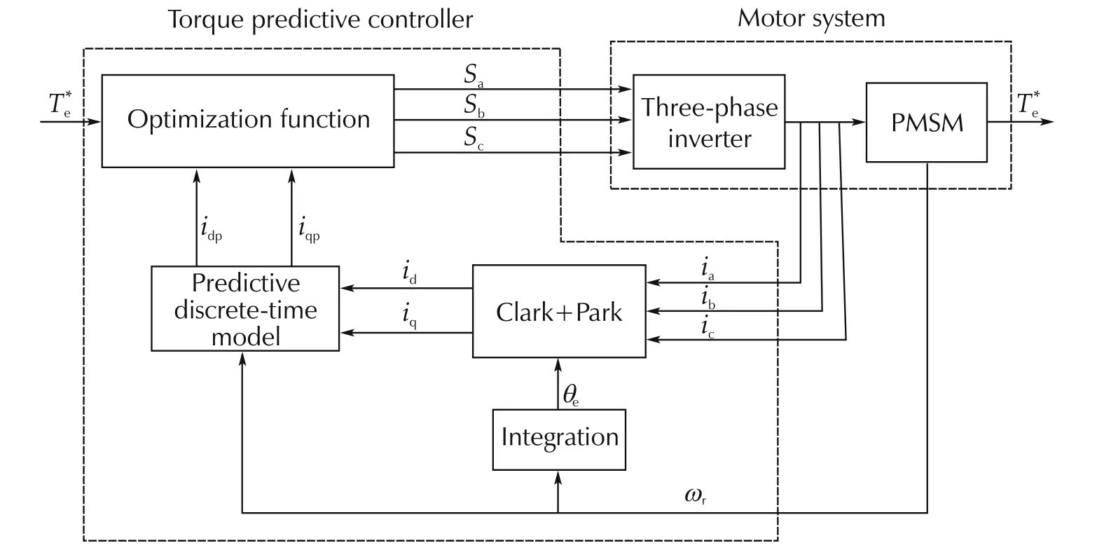
Fig.3 MPC-based torque control structure.
According to the MPC’s principle in[21,22],p is defined as predictive horizon to extend the forecast of the system future output.To simply the calculation,we set control horizon with the same value of predictive horizon p.At sample time k,U(k)is defined as the future control input sequence which is the optimization vector in the following cost function and X(k)is defined as the predictive state sequence,as follows:
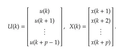
Each vector of U(k)and X(k)contains respectively an array of control inputs u and system states x. The reference current R(k)keeps the same value r in each predictive horizon.
3.2 Design of the optimization function
The main control requirements of PMSM are summarized as:
.Tracking torque demand;and.Energy consumption reduction.
Additionlly,current saturation constraints should be taken into account.
MPC can effectively deal with an optimization problem with multi-objective,multi-constraint and multivari-able for the complex engineering system optimization design.These objectives can be discussed in details in the following part.
The main control requirement is to ensure the PMSM tracking the torque demand from upper vehicle control system well.By using a rotating d-q reference frame oriented to the rotor magnetic field axis,each stator current component has a physical meaning.The real component Idis proportional to the reactive power,and the imaginary component Iqis proportional to the electromagnetic torque.
In order to achieve an expected torque commandfrom upper controller,the q axis reference currentis calculated by equation(10).Meanwhile,to reduce the reactive power and the magnetic resistance torque,the d axis current should be small and even close to zero.The detailed equation is given in(13):
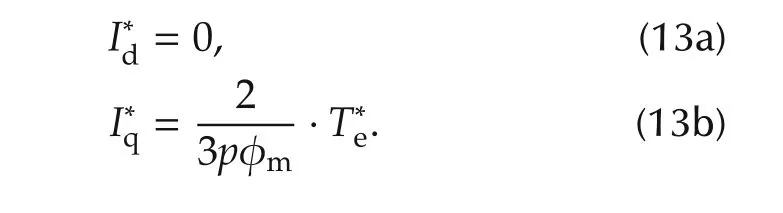
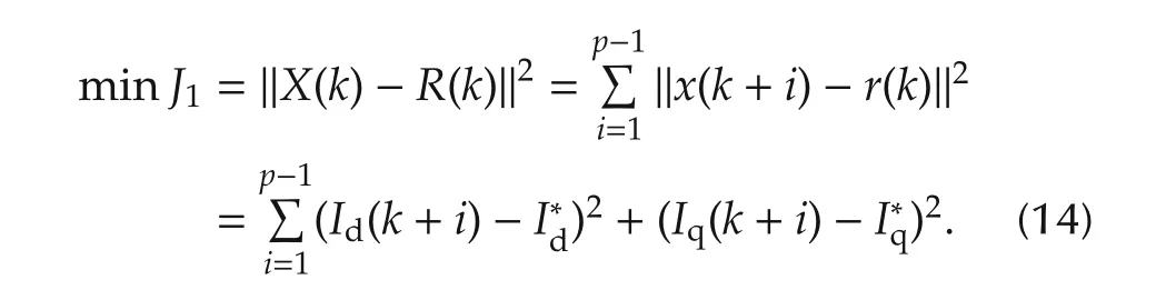
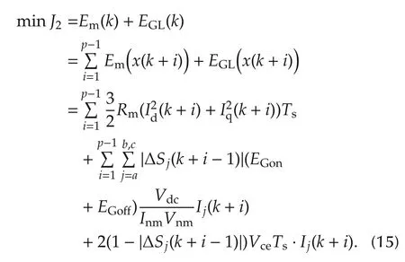
Therefore,the torque control problem is converted as a current tracking control problem,which can also reduce the reactive power and the magnetic resistance torque.The cost function of this control problem is designed as
Aiming at achieving good dynamic performance,the machine loss of PMSM system should be minimized in the cost function,which mainly consists of copper loss and inverter loss.The copper loss Emis produced by electrical currents in the conductors of transformer windings,which can be regarded as the heat energy of motor resistance[23].Additionally,frequent switching action of inverter can cause some power loss and switching oscillation,so energy losses of the inverter EGLneeds to be optimized,consisting of switching loss and conduction loss in equation(7),which can also reduce the number of switching action,thus indirectly avoiding the switch oscillation.Hence,the second cost function is designed to minimize energy losses of motor system during the total horizon:
In addition,in order to guarantee the terminal state of the closed-loop system into the stability region,we consider a terminal state function in the cost function,which penalizes the state at the end of the predictive horizon.This quadratic terminal cost is formed as

where P is a positive define and symmetric terminal penalty matrix.It should be pointed out that terminal penalty matrix P can be determined offline as[21],which can save the computing time of controller.
As equations(14),(15)and(16)mentioned above,a total objective function of the optimal control problem with constraints is defined over a receding horizon,as follows:

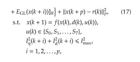
where Q and R denote weight matrixes of cost function.System dynamic constraint is to calculate the predictive state in each predictive horizon.The saturation constraint is an inequality constraint for each predictive state.
3.3 Optimization solution based on DP and pruning method
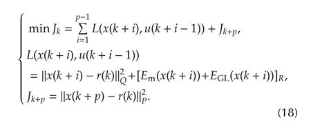
At the time instant k,if each predictive horizon is defined as each stage in control procedure,it is easy to observe from equation(17)that the MPC-based optimization is a multi-stage optimization problem.The optimal solution in Jkminimizes additive cost of each stage and satisfies the constraints of the states and inputs.Dynamic programming(DP)[19]is available for the solution to this discrete-time sequential decision process where the number of states is limited.Therefore,in order to fast solve this switching optimization problem in the MPC frame,we introduce the DP algorithm to build a searching tree to look for optimal input in each stage on the basis of optimality principle.
According to the DP algorithm,the multi-stage problem of MPC(17)can be disassembled into a set of lower-dimensional problems.Since control input u has finite candidate solution in discrete set{S0,S1,...,S7}and has to choose the best from this finite number of possibility,this can be seen as a discrete combinational optimization problem.When a candidate control input is chosen at a given state,the next state is fully determined;that is,for any state x(k),control u(k),and time k,the next state x(k+1)is determined.
In order to clearly analyze the optimization process,a searching tree is built for this multi-stage optimization problem.At simple time k,the current state is defined as the root of this searching tree.The candidate control input uj(k)is defined as one tree’s branch,where j=0,1,2,...,7.For different branches,the root grows different node xj(k+1)which is the predictive state for uj(k)in next stage.Every node contains the information of uj(k)and xj(k+1).While going to the next stage,the node also works as a father node to produce new nodes by choosing one branch from control candidate set.With the increasing of stages,the root x(k)will grow a large searching tree for the solution to optimization process.
According to the principle of optimality,DP algorithm is a kind of depth-first traversal for optimization solution.For initial root x(k),the optimal cost is given by the last step of the following algorithm,which proceeds backward in time from stage p to stage 1.We re-define
At stage m(1,2,...,p),the optimal cost is derived from
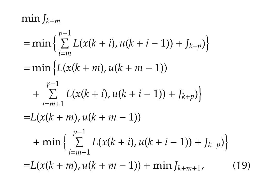
where the derivation provides an interpretation of Jk+mas the optimal cost function at stage m.Subproblems obtained after decomposition are not independent of each other.The sub-problem in the previous stage is further solved on the basis of a solution on the next stage.To achieve optimal control sequence U∗(k+m − 1)in cost function Jk+m,it needs to select the candidate branch u(k+m)in discrete finite control set{S0,S1,...,S7}to minimize the cost function Jk+m+1,then addof suboptimal control signal u(k+m)to Jk+m,compare Jk+mof each candidate branch to get optimal u∗(k+m − 1),and therefore,the optimal vector U∗(k+m − 1)=[u∗(k+m − 1);U∗(k+m)].
This solution algorithm mainly consists of two parts,like predicting output process and looking for optimal input.More specifically,the framework of the solution algorithm of the switching optimization based on DP is:
1)Initialize weight matrices Q,R,P,and stage p.
2)Measure the current state x(k),i.e.,Id(k),Iq(k),and ωr(k).
3)Set stage m=1.
4)Choose candidate branch ujin order from the discrete control set{S0,S1,...,S7},where j=1,2,...,7,then calculate predictive node xj(k+m)by equation(12),finally m=m+1.
5)If m<p,go back to step 4);else,go to next step.
6)Calculate the function L(x,u)for each candidate branch uj(k+m−1)in order by equation(18),where j=0,1,...,7,then calculate the cost function Jk+mon the basis of L(x,u)and previous(if m=p,=0).Minimize Jk+mto select the optimal input u∗(k+m − 1)and determine suboptimal control signal sequence U∗(k+m−1).Finally,m=m−1.
7)If m≥1,go back to step 6);else,go to step 8).
8)Apply the first optimal input u∗(k)to the PMSM system.End this algorithm.
Although DP algorithm can build a searching process of the real-time optimization solution,this method has to traverse each candidate signal in discrete control set,which is a heavy calculation burden.To reduce the number of switch states that enter the next predictive loop,we design a pruning method based on branch and bound strategy which is an algorithm design paradigm for discrete and combinatorial optimization problems[24].The algorithm explores the branches of this searching tree that represent subsets of the solution set by breadth-first searching.Therefore,a bounding function is designed to compute a lower bound for each node of the searching tree and woks as a problem-specific branching rule.While DP algorithm enumerates each candidate branch in one stage,the branch is checked by the bounding function,then if it cannot satisfy the branching rule,this branch is discarded and cannot run into next predictive stage.The searching tree can be shown as Fig.4.
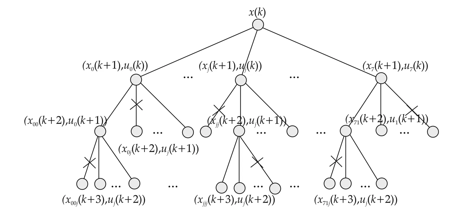
Fig.4 Pruning the searching tree.
A Lyapunov function has been proposed in[16]to prune the candidate inputs,but the function is simple and loose to check the stability performance.We design a complicated Lyapunov function and give a clear calculation to check the stability performance of the closed loop system before using the candidate inputs to predict the future states.Define˜x=x−r as the state of the closed-loop system.The Lyapunov function is defined as
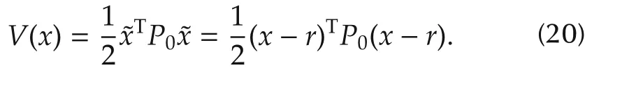
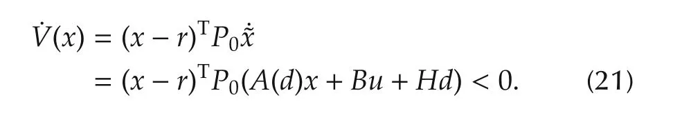
In order to ensure state˜x=[0 0]Tof the closed-loop system is stable,the P0is positive definite matrix and the derivative along the trajectory of V(x)is set as˙V(˜x)<0,as follows:
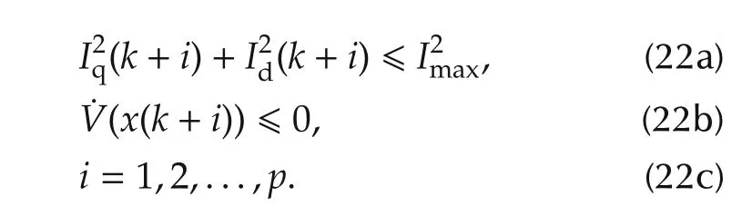
Therefore,the bound function for pruning branch of searching tree in each horizon can be set as
More specifically,the framework of this pruning branch algorithm in the predictive loop m(1,2,...,p)is:
1)Initialize matrix P0and current state x(k+m−1).
2)Choose one candidate input uj(k+m−1),j=0∶7.
3)Calculate predictive state x(k+m)by equation(12)and state error˜x(k+m)=x(k+m)−r(k).
4)Calculate the derivative of the Lyapunov function,˙V(x(k+m+1))by equation(21).
5)If˙V(x(k+m))<0 and I2q(k+m)+I2d(k+m)≤I2max,go to step 6);else,go to step 7).
6)Come into next predictive loop m+1 and go back to step 2).
7)Set the next cost functionof uj(k+m−1)as inf,stop going to next predictive loop,prune this candidate input in searching tree,and end this algorithm.
At previous m stage,for each candidate control signal u,the algorithm checks the bound function in equation(22),if beyond the limit,this candidate control signal can be discarded,since it will not lead to the optimal solution;else,it is preserved and continues coming into next predictive loop.This would prune the number of inputs to enter the next predictive loop and decrease the computational burden of evaluation of input sequences.Hence,the judgement condition about the bound function is only used once time for each control inputs in each predictive stage.The flow diagram of the proposed whole algorithm is presented in Fig.5.The predictive horizon p=2 in flow diagram and u∗(k+1)or u∗(k+2)can be determined as the same process with the blue flow blocks of u∗(k).Symbol j1,j2 denote the candidate solution numbers of the 1st and 2nd prediction stage,respectively.Itrequires multiple sets of tests toset these control parameters,like weight matrices Q and R.The optimal parameters are once determined and do not need to be updated online for different cases.Considering that both P0and Q affect tracking performance,we set P0is equal to matrix Q.Also,we calculate P for the terminal state function(16)as[21].
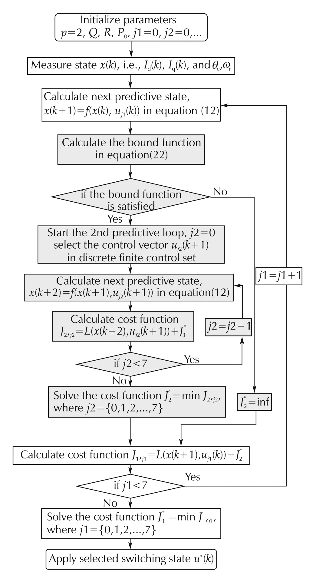
Fig.5 Control flow diagram of the proposed algorithm.
4 Simulation and analysis
In this section,simulation results are shown to demonstrate the validity of the proposed MPC strategy.The simulation is evaluated on an PMSM offline simulation platform in Simulink/Matlab.The detailed parameters of this PMSM system are shown in Table 1.
The reference torque input is set as a sinusoidal wave,in which the amplitude is 0.178N·m and the frequency is 1.59Hz.The rotor shaft mechanical speed is around 1200rad·s−1.The simulation time is set as 3s,the fixed step size Ts=0.1ms and predictive horizon p=3.The responses are compared between the cases before pruning and after pruning.Next,the results are pictured and compared,and the corresponding discussion is given in details.
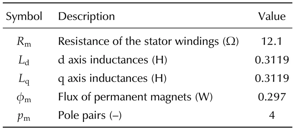
Table 1 Parameters of PMSM.
In Fig.6,the proposed strategy does not use pruning method to check searching tree.The simulation results illustrate that the actual value Iqis close to reference value I∗qwith the maximum tracking error less than 0.005A,and Idis changing around−0.03~0.03A.Also,the torque behavior Teis very smooth and tracks the reference torque input well.It shows that the proposed torque control strategy via switching optimization can effectively achieve the motor torque tracking control.But the calculation number of cost function is about 399 when p=3,which is a large computation burden as growth of predictive horizon.In Fig.7,the pruning method is added to the DP solution algorithm.The simulation results illustrate that the actual value Iqcan also track the reference value I∗qwell with the maximum tracking error less than 0.007A that is bigger than the case before pruning,and Idis changing around−0.02~−0.02A.Since the proposed method is a model-based optimization algorithm and the PMSM model is a relatively ideal linear model,the model error can cause a small tracking error.The curves of Iqand Idexist slight volatility due to switching optimization.The electromagnetic torque has a similar result as Iqcurve,and the maximum calculation number of cost function is about 22,which is very small.
In order to analysis the function of pruning method,we compare the results in Table 2.The standard deviation of Iqtracking error is increasing after pruning.Because some optimal control inputs and their branches cannot satisfy the bound function in equation(22),and have possibility to make the closed-loop system unstable,so these control inputs are cut out by pruning method.Meanwhile,the mean calculation amount of cost function is reduced from 399 to about 9.02 when horizon p=3,and from 19607 to about 107.9 when horizon p=5.To verify the computational efficiency of the optimization strategy,we recorded the total computational time for solving the optimization problem.The simulations are running on an eight-core Intel(R)Core(TM)i7 processor with 3.40 GHz processing speed per core and 3.2 GB of RAM available for Win7 32-bit systems.An estimation of CPU time is obtained in MATLAB with ode1(Euler)solver.These results reveal that for simulation time with 3s and sampling time Ts=0.1ms,the CPU time 44.62s of the pruning method is less than time 781.29s before pruning when horizon p=3.It is noted that the computational effort is reduced rapidly in each solution procedure.It shows that the optimization strategy with pruning branch method can still achieve accurate tracking control,and will increase the tracking error,but can greatly reduce the computational burden and decrease the loss of inverter to some extent.This is a trade off between control performance and computational efficiency.
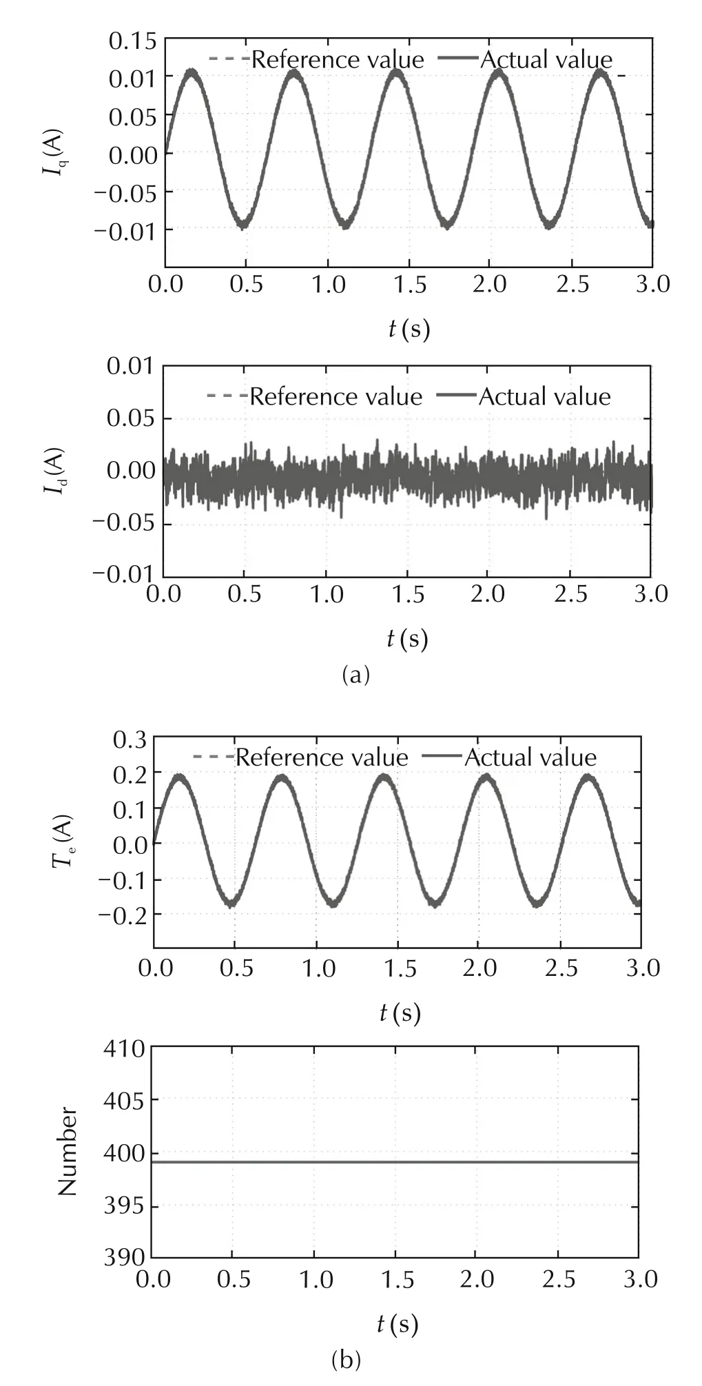
Fig.6 Simulation results of sinusoidal wave input before pruning.
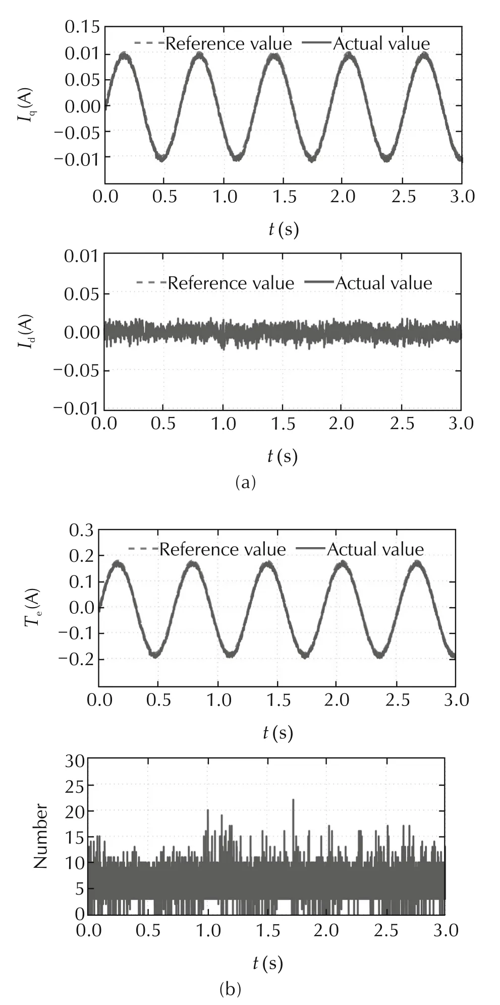
Fig.7 Simulation results of sinusoidal wave input after pruning.
In addition,in the hardware implementation process,to guarantee the switch stability,the switch dead time must be considered.When the single-phase switch signal changes,the switch turn-on command should wait for one dead time after the turn-off command,in order to avoid the single-phase bridge conduction due to shutdown delay,thus ensuring the stability of the inverter.
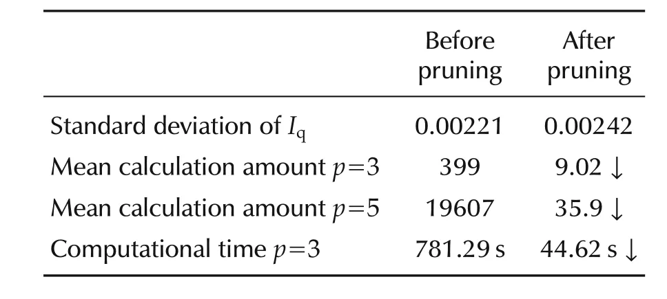
Table 2 Constractive analysis of the results.
5 Conclusions
In this paper,an MPC-based torque control for hybrid PMSM system is designed to track the torque demand and reduce energy loss.By applying DP algorithm with the pruning branch method,the searching tree for solution is built to look for the optimal control sequence,and the computational burden of input sequence evaluation is reduced in the control scheme.Finally,the simulation evaluates the proposed method can realize the online optimization solution and effectively control the PMSM system to track the torque command and achieve a trade off between satisfying control requirements and reducing computation burden.In addition,there are still some issues waiting to be explored in the future.We need to make an in-depth study on the MPC optimization strategy for hybrid motor system. Aiming at the engineering implementation,the experimental test needs to be developed to verify the real time performance of the proposed controller.
[1]B.Gasbaoui,A.Nasri.A novel 4WD electric vehicle control strategy based on direct torque control space vector modulation technique.Nonlinear Engineering,2012,3:236–242.
[2]P.Liu,H.P.Liu.Permanent-magnet synchronous motor drive system for electric vehicles using bidirectional Z-source inverter.IET Electrical Systems in Transportation,2012,4(2):178–185.
[3]C.H.T.Lee,K.T.Chau,C.H.Liu.Design and analysis of an electronic-geared magnetless machine for electric vehicles.IEEE Transactions on Industrial Electronics,2016,63(11):6705–6714.
[4]K.C.Kim.A novel calculation method on the current information of vector inverter for interior permanent magnet synchronous motor for electric vehicle.IEEE Transactions on Magnetics,2014,50(2):829–832.
[5]D.Casadei,F.Profumo,G.Serra.FOC and DTC:two viable schemes for induction motors torque control.IEEE Transactions on Power Electronics,2002,17(5):779–787.
[6]J.Rodriguez,P.Cortes.Predictive Control of Power Converters and Electrical Drives.Chichester:John Wiley&Sons,2012.
[7]T.Geyer,G.Papafortiou,M.Morari.Model predictive direct torque contro–Part I:Concept,algorithm,and analysis.IEEE Transactions on Industrial Electronics,2009,56(6):1894–1905.
[8]C.Bordons,C.Montero.Basic principles of MPC for power converters.IEEE Industrial Electronics Magazine,2015,9(3):31–43.
[9]P.K.Manakos,T.Geyer,N.Oikonomou,et al.Direct model predictive control:A review of strategies that achieve long prediction intervals for power electronics.IEEE industrial Electronics Magazine,2014,8(1):32–43.
[10]P.Cortes,M.P.Kazmierkowski,R.M.Kennel,et al.Predictive control in power electronics and drives.IEEE Transactions on Industrial Electronics,2008,55(12):4312–4324.
[11]F.Morel,X.F.Lin-Shi,J.M.Retif,et al.A comparative study of predictive current control schemes for a permanent-magnet synchronous machine drive.IEEE Transactions on Industrial Electronics,2009,56(7):2715–2728.
[12]M.Preindl,S.Bolognani.Model predictive direct torque control with finite control set for pmsm drive systems,part 1:Maximum torque per ampere operation.IEEE Transactions on Industrial Informatics,2013,9(4):1912–1921.
[13]J.J.Hong,D.H.Pan,Z.J.Zong.Comparison of the two current predictive-control methods for a segment-winding permanent-magnetlinear synchronous motor.IEEE Transactions on Plasma Science,2013,41(5):1167–1173.
[14]F.Barrero,J.Prieto,E.Levi,et al.An enhanced predictive current control method for asymmetrical six-phase motor drives.IEEE Transactions on Industrial Electronics,2011,58(8):3242–3252.
[15]S.Kouro,P.Corets,R.Vargas,et al.Model predictive controla simple and powerful method to control power converters.IEEE Transactions on Industrial Electronics,2009,56(6):1826–1838.
[16]G.Prior,M.Krstic.A control Lyapunovapproach to finite control set model predictive control for permanent magnet synchronous motors.ASME Journal of Dynamic Systems,Measurement,and Control,2015,137(1):1–10.
[17]M.J.Duran,J.Prieto,F.Barrero,et al.Predictive current control of dual three-phase drives using restrained search techques.IEEE Transactions on Industrial Electronics,2011,58(8):3253–3263.
[18]T.Geyer.Computationally efficient model predictive direct torque control.IEEE Transactions on Power Electronics,2011,26(10):2804–2816.
[19]D.P.Bertsekas.Dynamic Programming and Optimal Control.3rd ed.Nashua:Athena Scientific,2005.
[20]D.Graovac,M.P¨urschel.IGBT Power Losses Calculation Using the Data-Sheet Parameters.129th ed.Neubiberg:Infineon Technologies AG,2009.
[21]H.Chen,F.Allg¨ower.A quasi-infinite horizon nonlinear model predictive control scheme with guaranteed stability.Automatica,1998,34(10):1205–1217.
[22]H.Chen.Model Predictive Control.1st ed.System and Control Series.Beijing:Science Press,2013.
[23]J.F.Stumper,A.D¨oltinger,R.Kennel.Classical model predictive control of a permanent magnet synchronous motor.EPE Journal,2012,22(3):24–31.
[24]E.L.Lawler,D.E.Wood.Branch-and-bound methods:A survey.Operations Research,1996,14(4):699–719.
26 December 2016;revised 17 February 2017;accepted 17 February 2017
DOI10.1007/s11768-017-6193-z
†Corresponding author.
E-mail:chenh@jlu.edu.cn.Tel./fax:+86-431-85691900.
This work was supported by the NSFC Projects of International Cooperation and Exchanges(No.61520106008),the National Natural Science Foundation of China(Nos.61503149,U1564207)and the Graduate Innovation Fund of Jilin University(No.2016093).
©2017 South China University of Technology,Academy of Mathematics and Systems Science,CAS,and Springer-Verlag Berlin Heidelberg

Bingtao RENreceived the B.Sc.degree in Automation from Jilin University,Changchun,China,in 2012,where he is currently working toward the Ph.D.degree in Control Theory and Control Engineering.His current research interests include torque coordination optimization and motor control of electric vehicles.E-mail:tao11235821@163.com.

Hong CHENreceived the B.Sc.and M.Sc.degrees in Process Control from Zhejiang University,Zhejiang,China,in 1983 and 1986,respectively,and the Ph.D.degree in System Dynamics and Control Engineering from the University of Stuttgart,Stuttgart,Germany,in1997.Since1999,she has been a Professor in Jilin University,Changchun,China,where she currently serves as Tang Aoqing Professor and as the Director of the State Key Laboratory of Automotive Simulation and Control.Her current research interests include model predictive control,optimal and robust control,nonlinear control and applications in mechatronic systems focusing on automotive systems.E-mail:chenh@jlu.edu.cn.

Haiyan ZHAOreceived the B.Sc.degree in Automation,the M.Sc.and Ph.D.degree in Control Theory and Control Engineering from Jilin University,Changchun,China,in 1998,2004 and 2007,respectively.Since 2007,she has been a lecturer in Jilin University,Changchun,China.Her current research interests include vehicle stability control and state estimation of electric vehicles.E-mail:zhao_hy@jlu.edu.cn.

Wei XUreceived the B.Sc.degree in Automation from Harbin University of Science and Technology,Harbin,China,in 2010,and received the M.Sc.degree in Pattern Recognition and Intelligent System from Jilin University,Changchun,China,in 2015,where she is currently working toward the Ph.D.degree in Control Theory and Control Engineering.Her current research focuses on regenerative braking system of electric vehicles.E-mail:wei.xu.jlu@hotmail.com.
 Control Theory and Technology2017年2期
- Control Theory and Technology的其它文章
- Towards to dynamic optimal control for large-scale distributed systems
- Comparison of generalized engine control and MPC based on maximum principle
- Online calibration of combustion phase in a diesel engine
- Optimal heat release shaping in a reactivity controlled compression ignition(RCCI)engine
- Two-degree-of-freedom H-infinity control of combustion in diesel engine using a discrete dynamics model
- Experimental investigation of control updating period monitoring in industrial PLC-based fast MPC:Application to the constrained control of a cryogenic refrigerator