离心式水力空化发生器空化空蚀机制试验研究
2017-11-24 06:08刘厚林MatevDular
农业工程学报 2017年14期
王 健 ,刘厚林 ,Matevž Dular
(1. 泰州学院船舶与机电工程学院,泰州 225300;2. 江苏大学流体机械及工程技术研究中心,镇江 212013;3. Laboratory for Water and Turbine Machines, Faculty of Mechanical Engineering, University of Ljubljana, Ljubljana 1000, Slovenia)
离心式水力空化发生器空化空蚀机制试验研究
王 健1,刘厚林2,Matevž Dular3
(1. 泰州学院船舶与机电工程学院,泰州 225300;2. 江苏大学流体机械及工程技术研究中心,镇江 212013;3. Laboratory for Water and Turbine Machines, Faculty of Mechanical Engineering, University of Ljubljana, Ljubljana 1000, Slovenia)
该文对一台转子-定子型离心式水力空化发生器的性能进行了系统的试验研究,以寻求其空化生成机制并与空蚀分布之间的关系。可视化试验结果表明空化发生器内存在楔形槽空化、转子叶齿和定子叶齿前缘空化。通过水听器测量了空化发生器蜗壳侧面位置的压力脉动情况,在相同转速下压力脉动随着流量的增加而增大,压力脉动周期不变;在相同流量下压力脉动随着转速的增加而增大,周期减小:50 Hz时压力幅值为30 Hz时的2.5倍,周期缩短0.001 s。油墨法试验结果显示空蚀主要发生在转子叶齿尾端和中部,定子叶齿前缘空泡附着部分及尾端。楔形槽空化是造成破坏的主要原因,因其空化强度最高且空泡溃灭行为离固壁表面最近。该研究可为离心式空化发生器的研发提供参考。
水力;离心泵;空化;空化发生器;空蚀;可视化试验
0 引 言
一直以来空化都是制约水力机械发展的阻碍[1-4],但随着近年来对空化的理解与研究越发深入,研究人员发现若对空化的高湍流和高能量转换特性加以利用,空化可以成为一种具有广泛应用前景的技术手段。不但可以加速化学反应[5]、清洗管道[6]、处理污水[7-9],还可以为鱼雷等水下兵器减阻[10]。空化特有的易实现、低能耗且相对廉价的特点,使其在相关领域得到了越来越广泛的应用。因此研究高效节能的空化设备具有重要的意义。
目前研究比较广泛的空化水处理方法为超声波空化和水力空化,尤其针对前者的研究较为成熟。最早在 20世纪20年代,Harvey等[11]对超声波空化对微生物的分解能力进行了研究。20世纪80年代之后,随着超声设备的发展与普及,其应用得到了迅速的发展,涉及医学、有机合成、生物化学、材料加工、环境保护等多个方面[12-17]。尽管如此,超声波空化由于存在能耗高、空化区域小以及设备昂贵等缺点,限制了其实现工业化和产业化的进程[17]。
不同于超声波空化,水力空化可在各种不同的水力装置内实现,通过控制结构参数或动力源便可改变空化的长度,周期,强度等特性,效率更高。各国科研人员对水力空化的研究主要集中在细菌或杂质降解、分离、破坏以及加速化学反应等方面[18-25],对水力空化设备的空化性能关注较少,诸如压力损失过大,压力脉动幅度较小,空泡产出效率较低等问题。
近来主要使用的水力空化设备有文丘里管[18-22]和孔板[23-29]。Mohoklar等[30]利用一种连续气泡混合模型研究了文丘里管的一维气泡流动,结果显示气泡与气泡和气泡与液体的相互作用对气泡流型有重要影响。随后又对比了文丘里管和孔板装置的空化流场压力梯度,发现孔板射流的空化强度要高于文丘里管[31]。翟磊[32]研究了孔板几何参数对空化强度的影响关系,并基于此设计了一种孔板和文丘里管组合式空化发生器,能够显著提高单孔板或多孔板式空化发生器的空化性能。Kanthale等[33]采用数值模拟的方法研究了孔板空化在不同工况及系统参数下的空化强度。结果表明空化所引起的物理化学转变不仅仅是由空泡溃灭所造成的,还与空化发生器内的活性空化体积量有关。近来,在孔板射流的基础上发展出了一种新型的空化发生器,即将孔板设计为转子结构并置于定子腔内,流体流入转子内部后在离心力的作用下从转子表面分布的喷嘴流出形成空化,其运动模式与离心泵相同[34-35]。相比孔板水力空化设备单位能耗羟自由基可增大15倍,且所需时间缩短了70 min[36];液流速度可通过改变转子速度进行调节,控制简便,具有更大的优势与潜力。
本文是课题组早期工作的延伸[37-39],综合采用可视化试验、油墨试验等方法对课题组设计的离心式空化发生器的空化产生机制、压力脉动及其空蚀区域进行了研究,观测了发生器内的不同空化生成模式;分析了压力脉动随空化发展程度的变化规律;最后探讨了转子叶齿与定子叶齿空蚀区域的分布及其主要诱因。本文研究有利于进一步了解转子-定子式空化发生器的空化性能,为今后空化发生器结构的优化提供参考,有利于进一步实现空化水处理方法的产业化与工业化。
1 空化发生器基本参数与结构
本文研究的离心式空化发生器是由一台 ITT公司生产的离心泵改造而成。离心泵型号为SHE 40-160/40/P,流量调节范围Q=18~48 m3/h,对应扬程为H=18.5~35.5 m,叶轮外径D2=160 mm,蜗壳出口直径Dd=40 mm,叶片数z=6。额定功率为40 kW,额定转速为2 890 r/min。
离心式空化发生器的改造方法为:将原离心泵叶轮于径向80 mm处周向切割后加装一个与叶轮同时旋转的转子部件,并在泵腔中与转子相对的位置安装一个定子部件。转子与定子的结构如图 1所示,两者均为圆盘结构,靠近外缘一侧有12个大小相同的叶齿,定子的叶齿上开有楔形凹槽。转子和定子有叶齿的一侧相对布置,转子随原离心泵叶轮运动,转子与定子的相对运动形成成对的收缩流道,为空泡的形成创造了条件。图 1中右侧所示为转子-定子剖面图,图中左边固定静止的为定子,右侧旋转的为转子。转子和定子间的空隙由垫片数量控制。空化发生器装配图如图1a中所示,主要部件有:切割后的叶轮、定子、转子与蜗壳。
图1 空化发生器结构图Fig.1 Geometric structure of cavitation generator
2 试验测试系统与试验方法
本文试验于斯洛文尼亚卢布尔雅那大学(University of Ljubljana)机械工程学院水机实验室(Laboratory for Water and Turbine Machines)闭式空化试验台上进行,如图 2所示。利用离心式空化发生器自身离心泵作为试验台动力源。空化发生器进口前端装有稳压罐,确保来流稳定性。电磁流量计布置在空化发生器下游罐与稳压罐之间。
为了便于对空化发生器内部的空化进行可视化观测,在蜗壳侧面加装了观测窗,如图3a所示。空泡瞬态结构通过一台Fastec Imaging HiSpec4 2G mono型高速数码相机记录。照明设备采用两台LED灯,分别置于相机两侧,具体布置如图3b所示。
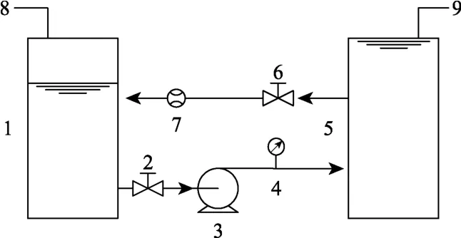
图2 闭式空化试验台示意图Fig.2 Schematic diagram of closed loop cavitation test rig
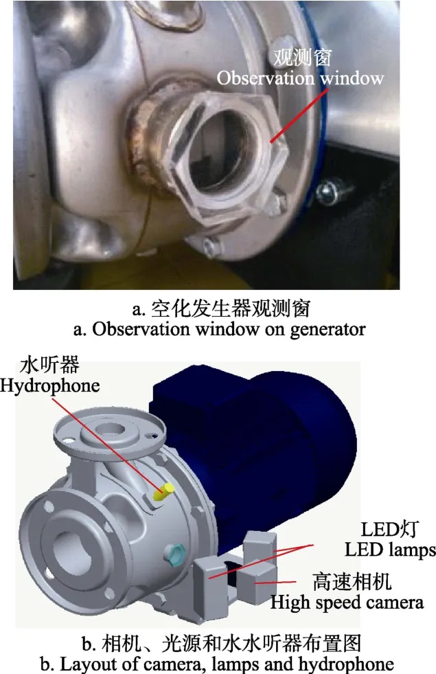
图3 观测窗、相机、光源和水听器布置图Fig.3 Layout of observation window, camera,light and hydrophone setups
本文将结合油墨法(用油墨将转子和定子进行喷涂)对转子和定子的空蚀区域进行研究。同时采用 Reson Hydrophone TC4013水听器测量转子与定子间的压力脉动情况,研究空化发生器在不同工况运行时的内部压力及空泡强度的改变对压力的影响。水听器的测量范围为1 Hz~170 kHz,安装在蜗壳隔舌附近,这是由于在蜗壳内此处的压力脉动变化最大,如图3b所示。试验中空化发生器的转速由变频器FUJI ELECTRIC FVR-E9S控制,实际转速由数字式转速表Velleman DTO6234测量。高速相机的采样频率设定为8 000帧/s,水听器采样频率设定为1 MHz。表1中给出了当转子与定子的间距为0.8 mm时空化发生器的试验工况。选取30,40与50 Hz,3种不同的电机驱动频率fd,每种频率下利用阀门调节空化发生器在 3种不同流量下运行,以便对比相同频率不同流量和相同流量不同频率的运行工况下空化发生器的性能。不同驱动频率下空化发生器的转速由转速表读取,分别为1 663,2 268和2 870 r/min。根据式(1)计算可得各驱动频率下空化发生器的轴频分别为 27.7、37.8和47.8 Hz,则其离心泵叶轮叶频与转子叶频可分别根据式(2)和式(3)fr=mfn计算。
式中n为空化发生器转速,z为离心泵叶轮叶片数,m为转子叶齿数,故离心泵叶轮叶频为6倍轴频6fn,转子叶频为12倍轴频12fn。
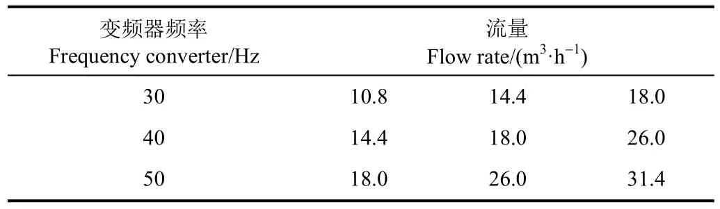
表1 空化发生器试验工况Table 1 Operating conditions of the cavitation generator
3 结果与分析
3.1 空泡瞬时形态分析
图4为运行工况为fd=50 Hz,Q=31.4 m3/h时,空化发生器内空泡瞬时形态。所取时间跨度为转子相邻两个叶齿经过观测窗口的过程,即保证一个完整的转子-定子叶齿交错周期。图4中工况周期为14Δt,其中Δt=0.125 ms。图中还给出了t=t0+6Δt时定子叶齿与转子叶齿的三维示意图,t0表示任意时刻。
在一个完整的运动周期内存在 3种空化模式。第一种为定子叶齿前缘空化(虚线框):当转子的一个叶齿向定子叶齿靠近时,带动流体掠过定子叶齿前缘,流场类似于钝头体绕流。转子-定子间的相对运动使得定子叶齿与转子叶齿间过流断面减小(t=t0+4Δt至t=t0+6Δt)),液体流速增加,在定子叶齿前缘形成附着空泡(t=t0+4Δt),并迅速发展扩大(t=t0+6Δt);当转子叶齿与定子叶齿开始交错重合时,由于转子叶齿的干扰(t=t0+8Δt),附着空泡急剧缩小并脱落(t=t0+10Δt),且从转子-定子的流道中溢出至转子-定子与蜗壳的间隙中,如图 4中t=t0+10Δt至t=t0+14Δt虚线框所示。但附着空泡并未完全消失,如图中点划线框所示。
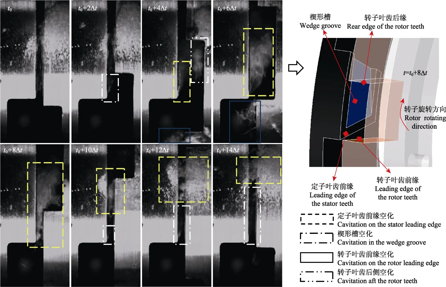
图4 空化发生器转子和定子叶齿交错时空泡瞬态分布(驱动频率fd=50 Hz,流量Q=31.4 m3·h-1)Fig.4 Cavitation distribution of cavitation generator as rotor and stator teeth staggering(Driving frequency fd=50 Hz, Flow rate Q=31.4 m3·h-1)
同时随着重合区域的增加,另外一种空化模式开始形成。由于定子叶齿上开有楔形槽,此时流道类似扩散管,未消失的附着空泡重新开始生长(点画线框t=t0+10Δt),直至转子叶齿开始与定子错开(t=t0+2Δt),以下称该空化模式为楔形槽空化。随后当t=t0+4Δt时,下一转子叶齿逼近,定子叶齿前缘空化开始发展。故在一个完整周期中,定子叶齿前缘经历 2次空化发展过程,分别为定子叶齿前缘空化与楔形槽空化。值得一提的是,当t=t0+4Δt时,可观察到一簇与附着空泡分离的空泡团体积迅速变大(双点划线框),这是由于转子定子叶齿错开后过流断面突然变大使附着空泡得以扩散并充分发展而脱落,也得益于转子的高速旋转在转子叶齿后侧形成了一个低压区。
第三种空化模式为转子叶齿前缘空化(实线框),如图4中t=t0+4Δt时刻和t=t0+6Δt时刻所示。这是由于转子高速旋转而在其前缘形成的钝头体绕流空化。该空化模式在定子与转子叶齿开始交错时与定子叶齿前缘空化的碰撞下消失,并对后者造成干扰使其脱落。
3.2 压力脉动分析
为了研究空化发生器内的压力脉动情况,图 5给出了驱动频率为50 Hz时,3种不同流量下的压力脉动时域图与频谱图。
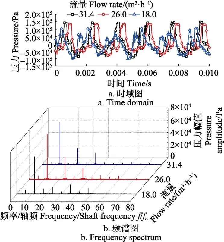
图5 不同流量下空化发生器内压力脉动时域频谱图(驱动频率fd=50 Hz)Fig.5 Time domain and frequency spectrum of pressure pulsation under different flow rate as fd=50 Hz
从图5a中可以发现,在0.01 s内,空化发生器在不同流量下的压力脉动周期一致,皆约为0.002 s;随着流量的增加,压力脉动幅值相应升高:从 18.0 m3/h时约1.0×105Pa上升至31.4 m3/h时约1.5×105Pa。另外需要注意的是,当流量为18.0 m3/h时,在任意一个周期内的波峰存在明显的驼峰现象,2个波峰幅值相当,且第二波峰略高;第一波峰则随着流量的增加逐渐减弱,当流量为31.4 m3/h时,第二波峰已明显高于第一波峰。
通过图5b中还可以发现,26.0 m3/h和31.4 m3/h流量下空化发生器的主频和次频与轴频的比值均为 12和24,即12倍轴频12fn与24倍轴频24fn,并非离心泵的叶轮叶频fb=6fn,而等于转子叶频fr=12fn与两倍转子叶频2fr;18.0 m3/h时主频同样为转子叶频,但次频则为三倍转子叶频 3fr,这可能是因为该流量下空化发生器内部流场受前文提及的驼峰现象的影响。
图6所示为空化发生器在不同驱动频率下流量相同时(Q=18.0 m3/h)的压力脉动时域图和频谱图。从图6a中可看出,当流量不变时,压力脉动随着驱动频率的增大而升高,脉动周期则随之缩短:驱动频率30 Hz时压力脉动幅值约为4.0×10⁴Pa,脉动周期约为0.003 s,且无驼峰现象,而驱动频率50 Hz时,压力脉动幅值增大了2.5倍,为1.0×10⁵Pa,而脉动周期则缩短了0.001 s。
图6b中由于驱动频率不同,故各频谱曲线的轴频不同。可以看出,压力脉动主频和次频的压力幅值均随着驱动频率的增加而显著升高;当驱动频率为 40 Hz和30 Hz时,由于无驼峰现象,故与驱动频率为50 Hz时不同,空化发生器的主频与次频分别等于转子叶频与两倍转子叶频。因此尽管空化的产生会影响腔内的压力脉动,但空化发生器的主频与次频主要由转子叶齿数决定。
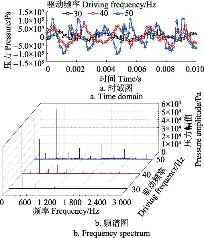
图6 不同驱动频率下空化发生器流量相同时压力脉动时域频谱图(流量Q=18.0 m3·h-1)Fig.6 Time domain and frequency spectrum of pressure pulsation under different driving frequency with same flow rate Q=18.0 m3·h-1
为了研究不同转子与定子间距对空化发生器腔内压力的影响,分别调整转子-定子间距从0.8 mm增加到3.8 mm和5.6 mm后对压力脉动进行测量,结果如图7所示。可以看出,随着间隙的增大,腔内的压力幅值有所减小,但降低幅度并不明显。压力脉动周期仍然保持一致。
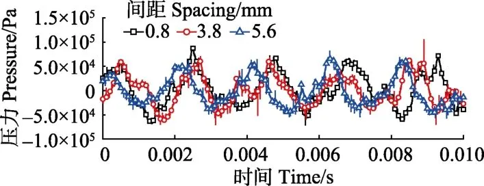
图7 不同转子定子间距压力脉动时域图(驱动频率 fd=40 Hz,Q=18.0 m3·h-1)Fig.7 Time domain of the pressure pulsation with different spacing between rotor and stator(Driving frequency fd=40 Hz, Flow rate Q=18.0 m3·h-1)
3.3 定子转子叶齿空蚀分析
为了确定空化发生器内的空蚀发生区域,采用油墨法进行了空蚀试验:使空化发生器在驱动频率为50 Hz,流量为31.4 m3/h的工况下持续运行30 min,令空泡充分腐蚀喷涂有黑色染料的转子和定子。试验结果如图 8所示,图中浅色区域为空蚀区域。
从图 8中可以看出,转子的腐蚀区域发生在叶齿尾缘以及叶齿中部;定子的腐蚀区域则主要发生在楔形槽空泡覆盖的区域,某些叶齿的尾端也有空蚀发生。从前文分析可知,离心式空化发生器主要有 3种空化形态,其中楔形槽空化形成时流道截面最小,流速最高,故空化强度最大[39],且产生的空泡距离固壁表面最近,空泡溃灭时释放的冲击波能量将直接作用在固壁表面造成破坏,故空蚀主要发生在楔形槽区域。同时由图 4的分析可知楔形槽空化从转子叶齿与定子叶齿大部分重合时开始初生,并在完全重合时发展完全并开始脱落,空泡的溃灭过程始于转子叶齿与定子叶齿开始错开,故转子的腐蚀区域集中在叶齿尾端与叶齿中部。另外值得注意的是转子叶齿前缘空化覆盖的区域则几乎没有油墨剥离,这也从侧面证明了空泡的溃灭行为发生在近壁面是造成空蚀的重要诱因。
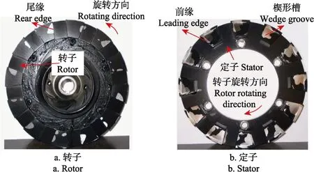
图8 转子与定子空蚀区域分布图Fig.8 Cavitation erosion distribution on rotor and stator
4 结 论
本文对一种离心式水力空化发生器进行了实验研究,系统分析了发生器的空化机制,压力脉动以及空蚀区域,主要结论如下。
1)空化发生器内的空化形成机制主要有转子与定子交错重合形成的楔形槽扩散空化,转子高速旋转形成的转子叶齿前缘空化与定子叶齿前缘空化。
2)在相同转速下,即空化发生器驱动频率为50 Hz时,腔内压力幅值随着流量的增加而增大,从18.0 m3/h时约1.0×105Pa上升至31.4 m3/h时约1.5×105Pa,而压力脉动周期不变,均约为0.002 s,且各流量下空化发生器主频均为转子叶频,即 12倍轴频;在相同流量下,即Q=18.0 m3/h时,腔内压力脉动幅值随着转速的增加而升高,脉动周期则随之缩短:驱动频率50 Hz时的压力脉动幅值约为30 Hz时的2.5倍,脉动周期则缩短了0.001 s,而主频则依然为相应驱动频率下的转子叶频。故空化发生器的主频主要由转子叶齿数决定,与转速和流量无关,即与空化的剧烈程度无关。当转子与定子间距变大时,压力脉动幅值有所减小,但降低幅度并不明显,压力脉动周期不变。
3)转子的腐蚀区域发生在叶齿尾端和中部;定子的腐蚀区域集中在叶齿前端与尾端。楔形槽空化是导致空蚀的主要原因,这是由于此时流道内流速最高,空化强度最大。转子叶齿前缘几乎没有空蚀,证明了空泡的溃灭行为发生在近壁面是造成空蚀的必要条件。
[1] 刘厚林,刘东喜,王勇,等. 三种空化模型在离心泵空化流计算中的应用评价[J]. 农业工程学报, 2012, 28(16):54-59.Liu Houlin, Liu Dongxi, Wang Yong, et al. Applicative evaluation of three cavitating models on cavitating flow calculation in centrifugal pump[J]. Transactions of the Chinese Society of Agricultural Engineering(Transactions of the CSAE), 2012, 28(16): 54-59. (in Chinese with English abstract)
[2] 邓育轩,李仁年,韩伟,等. 螺旋离心泵内回流涡空化特性[J]. 农业工程学报, 2015, 31(1): 86-90.Deng Yuxuan, Li Rennian, Han Wei, et al. Characteristics of backflow vortex cavitation in screw centrifugal pump[J].Transactions of the Chinese Society of Agricultural Engineering(Transactions of the CSAE), 2015, 31(1): 86-90.(in Chinese with English abstract)
[3] 张德胜,吴苏青,施卫东,等. 轴流泵小流量工况条件下叶顶泄露空化特性[J]. 农业工程学报,2013,29(22):68-75.Zhang Desheng, Wu Suqing, Shi Weidong, et al.Characteristics of tip leakage vortex cavitation in axial flow pump at small flow rate condition[J]. Transactions of the Chinese Society of Agricultural Engineering(Transactions of the CSAE), 2013, 29(22): 68-75. (in Chinese with English abstract)
[4] 阮辉,廖伟丽,罗兴锜,等. 叶片低压边的轴面位置对高水头水泵水轮机空化性能的影响[J]. 农业工程学报, 2016,32(16): 73-81.Ruan Hui, Liao Weili, Luo Xingqi, et al. Effects of low pressure meridional position on cavitation performance for high-head pump-turbine[J]. Transactions of the Chinese Society of Agricultural Engineering(Transactions of the CSAE), 2016, 32(16): 73-81. (in Chinese with English abstract)
[5] Pandit A B, Moholkar V S. Harness cavitation to improve processing[J]. Chemical Engineering Progress, 1996, 92(7):57-69.
[6] 王萍辉.空化射流在管道清洗中的应用[J].电力科学与工程,2002(4):21-24.Wang Pinghui. Application of cavitation jet to tubes and pipes cleaning[J]. Electric Power Science and Engineering,2002(4): 21-24. (in Chinese with English abstract)
[7] Sivakumar M, Pandit A B. Wastewater treatment: A novel energy efficient hydrodynamic cavitational technique[J].Ultrasonics Sonochemistry, 2002, 9(3): 123-131.
[8] Despo F K, Sureyya M, Sureyya M. Pharmaceutical residues in environmental waters and wastewater: Current state of knowledge and future research[J]. Analytical and Bioanalytical Chemistry, 2011, 399(1): 251-275.
[9] Kosjek T, Andersen H R, Kompare B, et al. Fate of carbamazepine during water treatment[J]. Environmental Science & Technology, 2009, 43(16): 6256-6261.
[10] 曹伟,魏英杰,王聪,等.超空泡技术现状:问题与应用[J].力学进展,2006,36(4):571-579.Cao Wei, Wei Yingjie, Wang Cong, et al. Current status,problems and applications of supercavitation technology[J].Advances in Mechanics, 2006, 36(4): 571-579. (in Chinese with English abstract)
[11] Harvey E N, Loomis A L. The destruction of luminous bacteria by high frequency sound waves[J]. Journal of Bacteriology, 1929, 17(5): 373-376.
[12] 甘雪萍,戴曦,张传福.超声空化及其在电化学中的应用[J].四川有色金属,2001,3(3):24-26.Gan Xueping, Dai Xi, Zhang Chuanfu. Ultrasonic cavitation and its application in the electrochemistry field[J]. Sichuan Nonferrous Metals, 2001, 3(3): 24-26. (in Chinese with English abstract)
[13] 王金刚,郭培全,王西奎,等.空化效应在有机废水处理中的应用研究[J].化学进展,2005,17(3):549-553.Wang Jingang, Guo Peiquan, Wang Xikui, et al. Research status of degradation and application of cavitation in organic wastewater treatment[J]. Progress in Chemistry, 2005, 17(3):549-553. (in Chinese with English abstract)
[14] 王磊,邱逦.超声空化效应在治疗领域中的研究进展[J].国际医学放射学杂志,2011,34(4):364-366.Wang Lei, Qiu Li. Advances of therapeutic ultrasound cavitation[J]. International Journal of Medical Radiology,2011, 34(4): 364-366. (in Chinese with English abstract)
[15] Petrier C, Jiang Y, Lamy M F. Ultrasound and environment:Sonochemical destruction of chloroaromatic derivatives[J].Environmental Science & Technology, 1998, 32(9): 1316-1318.
[16] 郭洪光,高乃云,姚娟娟,等.超声波技术在水处理中的应用研究进展[J].工业用水与废水,2010,41(3):1-4.Guo Hongguang, Gao Naiyun, Yao Juanjuan, et al. Research progress and development of ultrasonic technology applied in water treatment[J]. Industrial Water & Wastewater, 2010,41(3): 1-4. (in Chinese with English abstract)
[17] Gogate P R, Pandit A B. A review and assessment of hydrodynamic cavitation as a technology for the future[J].Ultrason Sonochem, 2005, 12(1): 21-27.
[18] Zupanc M, Kosjek T, Petkovsek M, et al. Removal of pharmaceuticals from wastewater by biological processes,hydrodynamic cavitation and UV treatment[J]. Ultrason Sonochem, 2013, 20(4): 1104-1112.
[19] Kalumuck K M, Chahine G L. The use of cavitating jets to oxidize organic compounds in water[J]. Journal of Fluids Engineering, 2000, 122(3): 465-470.
[20] Šarc A, Stepišnik P T, Petkovšek M, et al. The issue of cavitation number value in studies of water treatment by hydrodynamic cavitation[J]. Ultrasonics Sonochemistry,2017(34): 51-59.
[21] 许佳丽,黄永春,袁媛,等.基于文丘里管的水力空化降解壳聚糖的研究[J].食品工业科技,2016,37(2):244-248.Xu Jiali, Huang Yongchun, Yuan Yuan, et al. Study on the degradation of chitosan with hydrodynamic cavitation based on the venturi tube[J]. Science and Technology of Food Industry, 2016, 37(2): 244-248. (in Chinese with English abstract)
[22] 刘惠贤,何仁,黄永春,等.水力空化对羧甲基纤维素钠(CMC)溶液黏度的影响[J].食品工业,2014,35(6):34-36.Liu Huixian, He Ren, Huang Yongchun, et al. Influence of hydrodynamic cavitation on the viscosity of CMC solution[J].The Food Industry, 2014, 35(6): 34-36. (in Chinese with English abstract)
[23] 武志林,王伟民,李维新,等.水力空化联合臭氧氧化灭藻技术的实际应用[J].生态与农村环境学报,2016,32(3):500-506.Wu Zhilin, Wang Weimin, Li Weixin, et al. Practical application of technology combining ozonation with hydrodynamic cavitation to algae removal from water[J].Journal of Ecology and Rural Environment, 2016, 32(3):500-506. (in Chinese with English abstract)
[24] Zhang Z, Wang G, Nie Y, et al. Hydrodynamic cavitation as an efficient method for the formation of sub-100 nm O/W emulsions with high stability[J]. Chinese Journal of Chemical Engineering, 2016, 24(10): 1477-1480.
[25] 张茜,董志勇,陈乐,等.三角孔多孔板水力空化杀灭大肠杆菌的研究[J].水力发电学报,2016,35(8):65-71.Zhang Qian, Dong Zhiyong, Chen Le, et al. Experimental study on escherichia coli killed by hydrodynamic cavitation behind triangular multi-orifice plates[J]. Journal of Hydroelectric Engineering, 2016, 35(8): 65-71. (in Chinese with English abstract)
[26] 朱孟府,邓橙,宿红波,等.多孔孔板水力空化反应器的水力特性[J].环境工程学报,2013,7(2):546-550.Zhu Mengfu, Deng Chen, Su Hongbo, et al. Hydraulic characteristics of hydrodynamic cavitation reactor with orifice plate[J]. Chinese Journal of Environmental Engineering, 2013, 7(2): 546-550. (in Chinese with English abstract)
[27] 何志霞,陈驭航,纪长浩.多孔孔板水力空化可视化与数值模拟[J].农业机械学报,2016,47(2):396-401.He Zhixia, Chen Yuhang, Ji Changhao. Visualization and numerical simulation of hydrodynamic cavitationin multihole orifice plate[J]. Transactions of the Chinese Society for Agricultural Machinery, 2016, 47(2): 396-401. (in Chinese with English abstract)
[28] 师淑婷,晋日亚,杨思静,等.多孔水力空化装置降解甲基橙[J].环境工程学报,2016,10(3):1271-1275.Shi Shuting, Jin Riya, Yang Sijing, et al. Porous hydrodynamic cavitation device for degrading Methyl Orange[J]. Chinese Journal of Environmental Engineering,2016, 10(3): 1271-1275. (in Chinese with English abstract)
[29] 董志勇,徐琳香,李大炜,等.圆孔多孔板水力空化降解对硝基苯酚废水的试验研究[J].浙江工业大学学报,2015,43(3):275-278.Dong Zhiyong, Xu Linxiang, Li Dawei, et al. Experimental study on degradation of P-NP by hydrodynamic cavitation due to circular multi-orifice plate[J]. Journal of Zhejiang University of Technology, 2015, 43(3), 275-278. (in Chinese with English abstract)
[30] Moholkar V S, Pandit A B. Modeling of hydrodynamic cavitation reactors: A unified approach[J]. Chemical Engineering Science, 2001, 56(21): 6295-6302.
[31] Moholkar V S, Pandit A B. Numerical investigations in the behaviour of one-dimensional bubbly flow in hydrodynamic cavitation[J]. Chemical Engineering Science, 2001, 56(4):1411-1418.
[32] 翟磊.孔板型水力空化发生器结构优化及其性能评价[D].北京:中国石油大学(北京),2010.Zhai Lei. Structural Optimization and Performance Evaluation of Hydrodynamic Cavitation Reactor of Orifice Type[D]. Beijing: China University of Petroleum, 2010. (in Chinese with English abstract)
[33] Kanthale P M, Gogate P R, Pandit A B, et al. Dynamics of cavitational bubbles and design of a hydrodynamic cavitational reactor: Cluster approach[J]. Ultrason Sonochem,2005, 12(6): 441-452.
[34] Chahine G L, Kalumuck K M. Swirling fluid jet cavitation method and system for efficient decontamination of liquids:6221260[P]. 2001-04-24.
[35] Badve M, Gogate P, Pandit A, et al. Hydrodynamic cavitation as a novel approach for wastewater treatment in wood finishing industry[J]. Separation and Purification Technology, 2013(106): 15-21.
[36] 李翔.旋转空化发生器性能研究[D].浙江:浙江工业大学,2013.Li Xiang. Performance of Rotating Cavitation Reactor[D].Zhejiang: Zhejiang University of Technology, 2013. (in Chinese with English abstract)
[37] Petkovšek M, Zupanc M, Dular M, et al. Rotation generator of hydrodynamic cavitation for water treatment[J]. Separation and Purification Technology, 2013(118): 415-423.
[38] Petkovsek M, Mlakar M, Levstek M, et al. A novel rotation generator of hydrodynamic cavitation for waste-activated sludge disintegration[J]. Ultrasonics Sonochemistry,2015(26): 408-414.
[39] 王健.水力装置空化空蚀数值计算与试验研究[D].镇江:江苏大学,2015.Wang Jian. Numerical Simulation and Experimental Tests for Cavitation and Induced Erosion in Hydraulic Apparatus[D].Zhenjiang: Jiangsu University, 2015. (in Chinese with English abstract)
Experiment on cavitation erosion mechanism of centrifugal hydraulic cavitation generator
Wang Jian1, Liu Houlin2, Matevž Dular3
(1.School of Shipping and Mechatronic Engineering, Taizhou University, Taizhou225300, China;2.Research Center of Fluid Machinery Engineering and Technology, Jiangsu University, Zhenjiang212013, China;3. Laboratory for Water and Turbine Machines, Faculty of Mechanical Engineering, University of Ljubljana, Ljubljana1000, Slovenia)
The performance of a rotor-stator centrifugal cavitation generator was experimentally studied, aiming at investigating the correlation between its cavitation mechanism and damage distribution. The generator was modified from a centrifugal pump, including a cut impeller, a volute, a rotor and a stator. The rotor and stator consist of 12 teeth each, whereas the stator has wedge grooves on each tooth. Therefore, as the rotor spins, there are 12 nozzles when the rotor tooth overlaps the stator tooth. The experiments were conducted in a closed-loop test rig in the Laboratory for Water and Turbine Machines of University of Ljubljana, Slovenia. The cavitation generator was also used as a flow driver in the test. In order to study the cavitation mechanism, an observation window was mounted on the side of the generator volute. The cavitation evolution was recorded via a high speed camera accordingly. Based on the visualization tests, it is found that there are 3 kinds of cavitation generating mechanisms. One is produced in nozzle tubes formed by the interaction movement of the rotor and stator. The other two are caused by the high speed rotation of the rotor. One happens on the leading edge of the stator tooth as the rotor moves towards it. At the same time, the rotor itself generates bubbles on the leading edge of the tooth. Hence, in one rotor-stator teeth interlacing period, the cavitation generated on the leading edge of the stator (nozzle cavitation and rotating-induced cavitation)has 2 circulations. For detecting the cavitation intensity, the pressure pulsation between the rotor and volute was measured by a hydrophone under different operating conditions. The results show that the pressure pulsation increases as the flow rate increases while keeping the rotating speed constant, but the pressure pulsation cycle remains the same. As the driving frequency is 50 Hz, the pressure amplitudes under 18 and 31.4 m3/h are 1.0×10⁵and 1.5×10⁵Pa, respectively, while the cycle is approximately 0.002 s. Additionally, regardless of the flow rate, the dominant frequency is equal to the rotor blade-passing frequency, but not the impeller-passing frequency of the original centrifugal pump. That is to say, the dominant frequency is 12 times shaft frequency. When the flow rate remains the same (18 m3/h), the pressure pulsation rises with the increasing of rotating speed, whereas the cycle declines. As the driving frequency reaches 50 Hz, the pressure pulsations are nearly 2.5 times that when the driving frequency is 30 Hz, but its cycle increases from 0.002 to 0.003 s. And the domain frequencies under each driving frequency are still equal to the rotor blade-passing frequency. Meanwhile, the influence of the distance between rotor and stator on the pressure pulsation was also studied. The distance was adjusted by the shims under the stator. It is found that increasing the distance would slightly decrease the pressure. Furthermore, the oil ink painting approach was employed to investigate the erosion area of the cavitation generator. The result indicates that the rear part and the middle part of the rotor tooth are eroded. For the stator, the damage almost covers the wedge grooves and some rear part of the tooth, which means these parts are the potential erosive area. The nozzle cavitation is the dominant trigger for these damages, since it has the strongest cavitation intensity among the above discussed 3 kinds of cavitation generating mechanisms. When the teeth of the rotor and stator interlace each other, the flow velocity in the gap between the rotor and stator is getting faster, creating stronger cavitation intensity. Hence, the erosion area primarily locates on the wedge groove. Moreover, the nozzle cavitation initiates while the rotor tooth overlaps most part of the stator tooth, and starts to shed off as they begin to stagger, so the shed bubbles collapse downstream, contributing to damages on the rear part of both rotor and stator. It reveals that the cavitation erosion in hydraulic machinery is primarily caused by the collapse of bubbles that are close to the solid wall.
hydrodynamics; centrifugal pumps; cavitation; cavitation generator; cavitation erosion; visualization experiment
10.11975/j.issn.1002-6819.2017.14.007
TV131.63
A
1002-6819(2017)-14-0049-07
王 健,刘厚林,Matevž Dular. 离心式水力空化发生器空化空蚀机制试验研究[J]. 农业工程学报,2017,33(14):49-55.
10.11975/j.issn.1002-6819.2017.14.007 http://www.tcsae.org
Wang Jian, Liu Houlin, Matevž Dular. Experiment on cavitation erosion mechanism of centrifugal hydraulic cavitation generator[J]. Transactions of the Chinese Society of Agricultural Engineering (Transactions of the CSAE), 2017, 33(14): 49-55.(in Chinese with English abstract) doi:10.11975/j.issn.1002-6819.2017.14.007 http://www.tcsae.org
2017-01-24
2017-05-31
国家自然科学基金青年基金项目(51609164);江苏省自然科学基金青年基金项目(BK20160574);泰州学院博士/教授项目(QD2013002)作者简介:王 健,男,江苏泰州人,船舶与机电工程学院,讲师,博士,主要从事水力机械空化空蚀方面的研究。泰州 泰州学院船舶与机电工程学院,225300。Email:arieskin@126.com
猜你喜欢
Chinese Physics B(2022年11期)2022-11-21
流体机械(2022年8期)2022-10-13
火箭推进(2022年2期)2022-05-14
上海交通大学学报(2021年8期)2021-09-02
数字海洋与水下攻防(2021年2期)2021-05-08
流体机械(2021年1期)2021-02-23
中国铸造装备与技术(2018年3期)2018-06-08
舰船科学技术(2017年11期)2017-11-27
植物资源与环境学报(2017年3期)2017-10-12
船海工程(2015年4期)2016-01-05